Note : Les descriptions sont présentées dans la langue officielle dans laquelle elles ont été soumises.
CA 02720861 2010-10-07
WO 2009/124397
PCT/CA2009/000480
SIGNALING DEVICE FOR DETECTING THE
PRESENCE OF AN OBJECT
BACKGROUND OF THE INVENTION
Background and Technical Field
The invention relates to signaling devices and, more particularly, to
signaling apparatus for detecting the presence of an object and possible
movement thereof. The method aspects of the invention relate to methods for
using such signaling devices in hospital beds.
SUMMARY OF THE INVENTION
The present invention comprises a sheet switch for use with hospital
beds. The sheet switch includes a pair of planar sheets having facing
conductive
elements. The sheets are separated by one or more resilient compressible
separators. The separators compress under force so as to create contact
between the facing conductive elements. In this manner, the contact closes an
associated circuit so as to provide an electrical signal indicative of the
sheet
switch changing electrical states.
Still further, the pair of planar sheets can include a first layer sheet
and a second layer sheet. The facing conductive elements of the first layer
sheet
can include a first conductor, and a second conductor physically spaced apart
from the first conductor. The conductive elements of the second layer sheet
can
include a single conductive path.
1
CA 02720861 2010-10-07
WO 2009/124397
PCT/CA2009/000480
An electrical potential can be applied at a first level between the first
and second conductors. When the separators are compressed under force, the
single conductive path of the second layer will conductively contact both the
first
and second conductors of the first layer. This contact will cause the
electrical
potential between the first and second conductors to change from the first
level to
a second level, measurably different from the first level. When the electrical
potential has changed to the second level, the sheet switch can be
characterized
as being in a closed state.
The first conductor can be in the form of a pattern of first individual
conductor lines spaced apart in a parallel configuration, with a common line
conductively interconnecting together the individual conductor lines. The
second
conductor can be in the form of a pattern of second individual conductor
lines,
again spaced apart in a parallel configuration. A common conductor line
interconnects together the second individual conductor lines. Further, the
first
individual conductor lines can run substantially parallel to the second
individual
conductor lines, with the conductor lines of the first and second conductors
being
interspaced on the top layer. The single conductive path can be grounded and
include a series of ground conductor lines spaced apart in a parallel
configuration.
When the separators are collapsed as a result of externally applied forces, at
least
one of the ground conductor lines can electrically contact at least one of the
individual conductor lines of the first conductor and at least one of the
individual
conductor lines of the second conductor. The conductor lines can be composed
of conductive inks.
2
CA 02720861 2010-10-07
WO 2009/124397
PCT/CA2009/000480
Further, the facing conductive elements of the top layer can include
a first conductor, with the conductive elements of the bottom layer having a
second conductor. When separators are compressed under force, the first
conductor of the top layer can conductively contact the second conductor of
the
bottom layer. An electrical potential applied between the first and second
conductors at a first level when the conductors are maintained apart will
change to
a second level which is measurably different from the first level upon contact
of
the first and second conductors. The sheet switch can then be characterized as
being in a closed state. The facing conductive elements of the top layer sheet
can
be in the form of a sheet conductor, as well as the facing conductive elements
of
the bottom layer sheet. The sheet conductors can consist of conductive foil.
The sheet switch can be positioned on or adjacent a mattress of the
hospital bed. Also, the switch can be positioned below the bed frame of a bed.
The switch can be connected to a processor, with the processor having an input
signal representative of whether the switch is in a closed or open state. The
processor can generate output signals so as to generate alarms in response to
the state of the sheet switch. The alarms can include one or more of the
following: an alarm located at the hospital bed; an alarm located at a nurses
station; a visual indication located at a nurses station. Further, the
processor can
generate output signals in response to the input signal from the sheet switch
which will cause an operation of lighting adjacent the hospital bed. Still
further,
the processor can generate output signals which will cause mechanical
components of the hospital bed to raise the bed a predetermined amount.
3
CA 02720861 2010-10-07
WO 2009/124397
PCT/CA2009/000480
In accordance with another aspect, a signaling device detects the
presence or movement of an object. The device includes a first top sheet with
a
substantially planar configuration, and a second bottom sheet also having a
substantially planar configuration. One or more spacers are positioned between
the first and second sheets for collapsibly maintaining the first and second
sheets
a predetermined distance apart.
A first conductor is mounted to the first sheet, and a second
conductor is mounted to the second sheet. A power device establishes an
electrical potential between the first and second conductors at a first level,
when
the first and second sheets are maintained the predetermined distance apart.
The
spacers will at least partially collapse in response to the object exerting
forces
against the top of the first sheet or a bottom of the second sheet. This will
result
in physical contact of the first and second conductors. When the first and
second
conductors contact each other, the electrical potential will change to a
second
level measurably different from the first level.
In accordance with another aspect, a method for detecting the
presence or movement of an object on or adjacent a hospital bed includes
positioning a sheet switch on or adjacent portions of the bed. An electrical
signal
is applied to the sheet switch. The method further includes detecting forces
externally applied to the switch by the object, through detection of
electrical
potential across the sheet switch. Still further, the object can be a hospital
bed
patient, and the method can include positioning the sheet switch on a mattress
of
the bed in a position where the switch will be engaged by the person moving
relative to the mattress.
4
CA 02720861 2010-10-07
WO 2009/124397 PCT/CA2009/000480
In accordance with another aspect, the sheet switch can be
positioned below a bed frame of the bed and within crush zone areas. These are
areas where a person would be injured if located on the switch during
adjustment
of the bed, or an object within the crush zone areas would interfere with bed
movement if the object exerts forces on the switch during bed adjustment.
Still
further, the method concludes the step of reversing motorized adjustment of
the
bed in response to the object contacting the switch, and moving the bed in the
reversed direction a predetermined amount.
BRIEF DESCRIPTION OF THE DRAWINGS
The invention will now be described with respect to the drawings, in
which:
FIG. 1 is a perspective view of a hospital bed within which an
embodiment of the signaling device may be utilized;
FIG. 2 is a side, elevation view of the hospital bed illustrated in FIG.
1, and is included herein to indicate what can be characterized as zones of
danger
or "crush zones" around mechanical components of the hospital bed;
FIG. 3 is an exploded view of one embodiment of a signaling device
or sheet switch;
FIG. 4 is a perspective view of the sheet switch shown in FIG. 3, but
shown in an assembled configuration;
FIG. 5 is a planar and diagrammatic view of a bottom layer of the
sheet switch shown in FIG. 4, and particularly showing the conductor
configurations;
5
CA 02720861 2010-10-07
WO 2009/124397
PCT/CA2009/000480
FIG. 6 is a planar and diagrammatic view of the top layer of the
sheet switch shown in FIG. 4;
FIG. 7 is an enlarged view of a portion of the sheet switch shown in
FIG. 4;
FIG. 8 is a planar and diagrammatic illustration of a second
embodiment of the sheet switch or signaling device;
FIG. 8A is a planar and diagrammatic view of the top layer of the
sheet switch shown in FIG. 8;
FIG. 8B is a planar and diagrammatic view of the bottom layer of the
sheet switch shown in FIG. 8;
FIG. 9 is a partial and side, elevation view of the sheet switch shown
in FIG. 8, taken along section lines 9-9 of FIG. 8;
FIG. 10 is a side, elevation view of a third embodiment of the sheet
switch or signaling device;
FIG. ills a partially schematic and partial circuit block diagram of
an embodiment of a switching circuit which can be used with the three
embodiments of the sheet switch;
FIG. 12 is a perspective view of the hospital bed illustrated in FIGS.
1 and 2, and showing relative positioning of three of the second embodiments
of
the sheet switches as mounted to a castor cover, lower leg cover and upper leg
cover of the hospital bed; and
FIG. 13 is a software sequence diagram illustrating various functions
which can be performed through use of the sheet switches, with respect to
various
features associated with the hospital bed and surrounding environment.
6
CA 02720861 2010-10-07
WO 2009/124397
PCT/CA2009/000480
DETAILED DESCRIPTION OF THE INVENTION
The principles of the invention will now be disclosed, by way of
example, with respect to embodiments of signaling devices or sheet switches
for
detecting movement or the presence of objects, as illustrated in FIGS. 1-13.
One
preferred embodiment of the invention, makes it possible for personnel at the
monitoring stations to have means for determining if a patient is entering a
hospital bed, exiting the bed or has inadvertently fallen from the bed.
Monitoring
personnel have the capability of detecting patient movement relative, for
example,
to the hospital bed mattress, sheets covering the mattress, or portions of the
sheets.
The preferred embodiment signaling devices are also advantageous
in detecting obstacles or other obstructions to movement of structural
components, as for example in motor driven hospital beds. Thus, obstacles
which
would impair structural movements in powered hospital beds are detected prior
to
the occurrence of any mechanical damage to the hospital bed components. Even
more importantly, the positioning in harms way of portions of the patient or
other
hospital personnel operating around the hospital bed, is detected, and injury
avoided.
To understand the features of the embodiments of the signaling
devices, FIGS. 1 and 2 illustrate a hospital bed 100 having moveable
components
for adjusting bed height and possible other parameters of the bed
configuration.
The embodiments of the signaling devices as described herein may be adapted
for use with the hospital bed 100. More specifically, the bed 100 can include
a
substantially horizontal upper frame 102, with a mattress 104 positioned
thereon.
7
CA 02720861 2010-10-07
WO 2009/124397
PCT/CA2009/000480
At the front of the bed 100 is a conventional headboard 106, while a
conventional
end board 108 is connected to the upper frame 102 at the end of the bed 100.
Side boards 110 are positioned on each side of the bed 100. Such side boards
110 may be moveable so as to facilitate entry and exit of a patient with
respect to
the bed.
The hospital bed 100 includes two leg assemblies, identified as a
head leg assembly 112 and an end leg assembly 114. The leg assemblies 112,
114 include leg covers 118 which can be connected at the upper portions
thereof
to the upper frame 102 through slide couplings 120. The bed 100 also includes
two pairs of pivot couplings 116. The pivot couplings 116 are also connected
to
portions of the upper frame 102. Further, the pivot couplings 116 include
pivot
connections to the leg covers 118, as well as to caster shields 122. The
caster
shields 122 are used to cover two pairs of casters 124. It should be
emphasized
that the hospital bed 100 is merely one example of a type of structure which
may
be used with the embodiments of the signaling devices described herein.
In accordance with the embodiments described herein, signaling
devices can be associated with the mattress 104 (or sheet materials covering
the
mattress 104) so as to detect a patient's movement relative to the area of the
mattress 104.
Hospital beds such as the hospital bed 100 include moving
mechanical components for purposes of, for example, adjusting the height of
the
bed 100. In this regard, and with reference to FIGS. 1 and 2, it can be seen
that
motor driven forces can be applied to components such as the leg assemblies
112, 114 and slide couplings 120 so as to cause the leg covers 118 to pivot
8
CA 02720861 2010-10-07
WO 2009/124397
PCT/CA2009/000480
relative to the upper frame 102 through the pivot couplings 116 and slide
couplings 120. With such action, and with the upper frame 102 being maintained
in a horizontal configuration, the height of the upper frame 102 relative to a
floor or
other supporting structure can be adjusted. However, adjustment of structures
such as hospital beds can be impaired by obstacles or other obstructions to
movement of the mechanical components of the bed. For example, and with
reference to FIG. 2, the areas marked as triangular areas 126 and 128 can be
characterized as "crush zones," in that they represent areas above the leg
assemblies 112, 114 and caster shields 122 where movement of mechanical
components of the bed 100 is occurring during bed height adjustment.
Accordingly, obstacles or other obstructions within these zones 126, 128 may
substantially impair proper operation of the bed adjustment, damage bed
equipment, and even be dangerous for the patient or hospital personnel
physically
adjacent to the bed 100. In a similar manner, another crush zone identified as
crush zone 130 exists in an area which is below the leg covers 118. As the
upper
frame 102 of the hospital bed 100 is lowered, the leg covers 118 will
essentially
"flatten out," with the area between the lower surfaces of the leg covers 118
and
the floor being continuously reduced.
For purposes of providing detection of movement of a patient
relative to different locations associated with the mattress 104, and for
purposes
of detecting the presence of obstacles or other obstructions to motor driven
movement of mechanical components of the bed 100 when the height or other
positions of the bed 100 is being manipulated, a signaling device 140 can be
utilized. One embodiment of the signaling device 140 is illustrated in FIGS. 3
- 7
9
CA 02720861 2010-10-07
WO 2009/124397
PCT/CA2009/000480
as sheet switch 142. A concept associated with the sheet switch 142 is the
generation of a switched electrical signal in response to contact across at
least a
limited area by another entity. The other entity could be a moving patient in
the
case of the sheet switch 142 being associated with one or more areas of
mattress
104 (or locations adjacent thereto), where a patient may contact the sheet
switch
142 when entering or exiting the hospital bed 100. Further, the sheet switch
142,
as described in subsequent paragraphs herein, can be positioned on other
components of the hospital bed 100, so as to provide for a switched signal in
response to such other components contacting an obstacle or other type of
obstruction.
Referring to the drawings, the sheet switch 142 can consist of a
bottom layer or sheet 144 and top layer or sheet 160. The bottom layer 144 of
the
sheet switch 142 consists of what can be characterized as an electrified grid
146.
The electrified grid 146 includes a first conductor 148. The conductor 148 can
be
a pattern of individual conductor lines 150 which are spaced apart in a
parallel
configuration. A common conductor line 152 can run perpendicular to the
individual conductor lines 150 and conductively interconnect together the
individual lines 150. In this manner, a continuous conductive path is formed
by
the first conductor 148. The first conductor 148, and other conductor lines
described herein, can be formed through the use of conductive inks. The
conductive inks can be then formed on the bottom layer 144 through the use of
silk screening in a desired pattern. The bottom layer 144 itself can be a
substrate
sheet formed from a suitable plastic material, such as ABS. One end of the
common conductor line 152 can be connected in a suitable manner to a first
cable
CA 02720861 2010-10-07
WO 2009/124397
PCT/CA2009/000480
154, which can be in the form of a ribbon cable or the like. The first cable
154 can
then be connected to a suitable first connector or terminal 156.
Referring in particular to FIG. 5, the electrified grid 146 of the bottom
layer 144 of the sheet switch 142 further includes a second conductor 162. The
second conductor 162 can be in a pattern of second individual conductor lines
164. The second individual conductor lines 164, like the first individual
conductor
lines 150, are individually spaced apart in a parallel configuration. As
further
shown, the second individual conductor lines 164 also run parallel to the
first
individual conductor lines 150, with each of the second individual conductor
lines
164 interspaced between two adjacent first individual conductor lines 150. A
second common conductor line 166 can run perpendicular to the second
individual conductor lines 164 and conductively interconnect together the
lines
154. In this manner, a continuous conductive path is formed by the second
conductor 162. As also shown in FIG. 5, the second common conductor line 166
can run essentially parallel to the first common conductor line 152, and can
be
located on an opposing side of the bottom layer 144 from a side on which the
first
common conductor line 152 is located. One end of the second common
conductor line 166 can be connected in a suitable manner to a second cable
168,
which can be in the form of a ribbon cable or the like. The second cable 168
can
then be connected to a suitable second connector or second terminal 170. In
accordance with the foregoing, the continuous conductive path formed by the
first
conductor 148 is physically and electrically separate from the continuous
conductive path formed by the second conductor 162. Further, the first
individual
conductor lines 150 and second individual conductor lines 164 are sufficiently
11
CA 02720861 2010-10-07
WO 2009/124397
PCT/CA2009/000480
spaced apart so as to ensure that there is no spatial conductivity between
adjacent ones of the lines 150 and 164, given the voltage potentials
(described
subsequently herein) which may be applied to the first and second conductors
148, 162, respectively. An adhesive 145 can be applied to the bottom of the
bottom layer 144, for purposes of securing the switch 142 to portions of the
bed
100.
Reference is now made to FIGS. 3, 4, 6 and 7, which illustrate the
top layer 160 of the sheet switch 142. As particularly shown in FIGS. 3 and 6,
the
top layer 160 includes a ground conductor 172. The ground conductor 172
includes a series of ground conductor lines 174, with the conductor lines 174
spaced apart in a parallel configuration. The ground conductor lines 174 are
commonly interconnected to a common ground representatively shown as ground
path 176. As further shown in FIG. 3 in an exploded format, the top and bottom
layers 160, 142, respectively are maintained in a physically separate
configuration
by a series of collapsible and/or compressible spacers (which can be
characterized as resilient separators) 178. The spacers 178 can be formed of a
suitable material which is composed of appropriate compressible or collapsible
material which will substantially collapse when forces are exerted on one or
both
ends of the spacers 178. Such material may consist of polyester,
polycarbonate,
or materials of similar properties.
When the sheet switch 142 is in use, a voltage or electrical potential
can be applied between the first connector 156 and the second connector or
terminal 170. The application of this voltage potential across connectors 156,
170
will correspondingly cause a voltage potential to exist between the first
conductor
12
CA 02720861 2010-10-07
WO 2009/124397
PCT/CA2009/000480
148 and the second conductor 154. With this potential across the conductors
148,
162, the sheet switch 142 can be characterized as being in an "open" state.
The
electrical potential can be applied through a battery or other desired power
source. For purposes of illustration, the terminal 264 having a "+V" symbol
(for
voltage potential) in FIG. 11 represents a battery or other power source.
If the sheet switch 142 (along with a series of other sheet switches
142) is used on or adjacent the mattress 104 of the hospital bed 100, it can
provide for detection of movement of a patient into or out of the hospital bed
100,
or to detect other patient movement. In the event of such movement, the
patient's
actions will cause the patient to contact the top layer 160 of the sheet
switch 142.
This contact will correspondingly exert forces on the top layer 160 and the
spacers
178 positioned between the top layer 160 and the bottom layer 144. These
forces, in turn, will cause one or more of the spacers 178 to compress or
collapse.
This collapsing of the spacers or separators 178 will result in the top layer
160
moving toward the bottom layer 144. With sufficient movement, one or more of
the ground conductor lines 174 will contact one or more of the first
individual
conductor lines 150 and one or more of the second individual conductor lines
164.
With the ground conductor lines 174 in contact with lines 150, 164, a
conductive
path will be established between the first and second conductors 148, 162,
respectively. With the establishment of this conductive path, and assuming low
resistance in the conductive paths, the voltage potential between the first
connector 156 and the second connector 170 will essentially drop to zero. In
fact,
even if there is more than just minimal resistance within the conductive
paths, the
voltage potential existing between the first connector 156 and the second
13
CA 02720861 2010-10-07
WO 2009/124397
PCT/CA2009/000480
connector 170 will measurably change upon contact of the ground conductor 172
with the conductors 148, 162, assuming that a sufficient potential originally
existed
between the connectors 156, 170. With the ground conductor 172 establishing a
conductive path between the first and second conductors 148, 162,
respectively,
the sheet switch 142 can be characterized as being in a "closed" state. In
this
regard, FIG. 7 is an enlarged view of a portion of the sheet switch 142 when
one
of the ground conductor lines 174 is in contact with two of the first
conductors 148
and one of the second conductors 162, which is spaced intermediate the two
contacted first conductors 148. These contacts are shown as being made at
locations 180, 182 and 184.
In accordance with the embodiment comprising the sheet switch 142
as illustrated in FIGS. 3 - 7, the sheet switch 142 can be used as a means for
electrically detecting the exertion of forces on the sheet switch 142 from an
external entity. In this particular embodiment, the sheet switch 142 includes
a
bottom layer 144 having a pair of conductors which will "normally" have an
electrical potential existing across the conductors, absent extremely applied
forces. A separate top layer 160 includes a ground conductor 172. When
external forces are applied to the top layer 160, the layer 160 will collapse
against
the bottom layer 144. This collapsing action will cause the ground conductor
172
to physically contact one or more portions of the first conductor 148 and the
second conductor 162. This contact will establish a conductive path between
the
conductors 148, 162, which can essentially be characterized as "closing a
switch"
between the conductors. Even with some resistance within the conductors 146,
162 and 172, the electrical potential between the conductors 148, 162 will be
14
CA 02720861 2010-10-07
WO 2009/124397
PCT/CA2009/000480
substantially reduced. Accordingly, this conductor configuration of the sheet
switches 142 can essentially establish a "binary" switch. The binary switch
can be
characterized as having a normally "open" configuration, in the absence of
externally applied forces. In the presence of externally applied forces, the
binary
switch will essentially be converted to what can be characterized as a
"closed"
state.
Further in accordance with the foregoing description, the conductors
148, 162 on the bottom layer 144 and the conductor 172 on the top layer 160
can
be characterized as "facing conductive surfaces." When contact is made, the
action can be characterized as closing an associated circuit so as to provide
an
electronic or electrical signal.
An alternative embodiment of a signaling device and sheet switch is
illustrated in FIGS. 8, 8A, 8B and 9 as sheet switch 202. With the sheet
switch
142, first and second conductors 148, 162, respectively were both incorporated
on
the bottom layer 144 and, absent contact with the top layer 160, maintain a
voltage differential between the conductors. The switch 142 was essentially
"closed" when the ground conductor 172 made contact with both the first and
second conductors 148, 162. In contrast, the sheet switch 202 essentially
includes one "side" of the switch being mounted to one layer thereof, while
the
"other side" of the switch (which can be at ground potential) is located on
the other
layer.
More specifically, the sheet switch 202 includes a top layer 204
(shown separately in FIG. 8A) and a bottom layer 206 (shown separately in FIG.
8B). When viewed from above, as in FIG. 8, the conductors of the layers form
CA 02720861 2010-10-07
WO 2009/124397
PCT/CA2009/000480
what can be characterized as an electrified grid 208. Referring specifically
to the
top layer 204, the layer includes a first conductor 210. The conductor 210 can
be
formed in a pattern of individual first conductor lines 212 which, in this
particular
embodiment, are shown as being individually spaced apart in a parallel
configuration. A first common conductor line 214 can run perpendicular to the
individual conductor lines 212 at one end thereof, and conductively
interconnect
the lines together. In this manner, a continuous conductive path is formed by
the
first conductor 210. As previously described with respect to the sheet switch
142,
the conductor lines can be formed in a pattern through the use of silk
screening
with conductive inks. Further, the top layer 204 can be formed as a substrate
sheet from a suitable plastic material, such as ABS. One end of the common
conductor line 214 can be connected in a suitable manner to a first cable 216.
The cable 216 can be connected to a first connector or terminal 218.
With reference now primarily to FIG. 8B, the bottom layer 206
includes a second conductor 220. If desired, the second conductor 220 can be
at
a ground potential. The second conductor 220 can be a conductive sheet or,
alternatively, can be in the form of second individual conductor lines 222.
The
second individual conductor lines 222, like the first individual conductor
lines 212,
can be individually spaced apart in a parallel configuration. Further, the
second
individual conductor lines 222 can be configured so as to have their
longitudinal
axes running in a direction having a 90 differential from the direction of
the
longitudinal axes of the first individual conductor lines 212 of the top layer
204. A
second common conductor or ground line 224 can run perpendicular to the
second individual ground conductor lines 222 and conductively interconnect
them
16
CA 02720861 2010-10-07
WO 2009/124397
PCT/CA2009/000480
together. In this manner, a continuous conductive path is formed by the second
conductor or ground conductor 220. As further shown in FIG. 8B, one end of the
second common conductor or ground line 224 can be connected in a suitable
manner to a second cable 226. In turn, the cable 226 can then be connected to
a
suitable second or ground connector 228.
With reference primarily to FIGS. 8 and 9, and in a manner similar to
the previously described sheet switch 142, the top layer 204 and bottom layer
206
of the sheet switch 202 are spaced apart through the use of individual spacers
230 which can be positioned in any of a number of suitable patterns, and
coupled
to the bottom of the top layer 204 and the top of the bottom layer 206. As
earlier
described, the spacers 230 may be composed of a polyester or polycarbonate
material. The spacers can be positioned around the parameter of the top and
bottom layers 204, 206, respectively, as well as in a suitable design for
ensuring
detection of forces exerted on the sheet switch 202. As previously described
with
respect to the sheet switch 142, the spacers 230 of the sheet switch 202 are
designed so as to collapse upon the application of external forces to the
sheet
switch 202, resulting in the top layer 204 contacting the bottom layer 206. As
with
switch 1142, an adhesive 223 can be applied to the bottom of the bottom layer
206 to secure the switch 202 to portions of the bed 100.
When the sheet switch 202 is in use, a voltage potential (being non-
zero relative to ground) can be applied to the first conductor 210 through the
first
connector 218. Application of this voltage potential to the first connector
218 will
correspondingly cause a voltage potential to exist between the first conductor
210
17
CA 02720861 2010-10-07
WO 2009/124397
PCT/CA2009/000480
and the second ground conductor 220. With this potential across the conductors
210, 220, the sheet switch 202 can be characterized as being in an "open"
state.
The sheet switch 202 (like the sheet switch 142) can be used on or
adjacent the mattress 104 of the hospital bed 100, so as to detect patient
movement. The use of a sheet switch for detecting patient movement was
previously discussed with respect to the switch 142. In addition to detecting
patient movement, the sheet switch 202 (as well as the sheet switch 142) can
also
be used in various other areas of the hospital bed 100 so as to detect the
existence of obstacles or other obstructions to various mechanical movements
of
the bed 100. For example, FIG. 12 illustrates the positioning of sheet
switches on
both the top and bottom portions of the leg covers 118, as well as on the
caster
shields 122. As previously described with respect to FIGS. 1 and 2, physical
areas around the hospital bed 100 can be characterized as crush zones, such as
crush zones 126, 128 and 130 previously described herein. Within these crush
zones, obstacles or other types of obstructions may impair mechanical movement
of the hospital bed 100. With the sheet switches 202 positioned as shown in
FIG.
12, and assuming that mechanical components of the hospital bed 100 are
moving so as to adjust the height or other parameters of the bed 100,
obstacles or
other obstructions in the crush zones would result in forces being exerted on
one
or more of the sheet switches 202. This contact and exertion of forces will be
translated to forces applied to the top layer 204 and the spacers 230
positioned
between the top layer 204 and the bottom layer 206 of one or more of the sheet
switches 202. These forces, in turn, will cause one or more of the spacers 230
to
collapse. This collapsing of the spacers 230 will result in the top layer 204
moving
18
CA 02720861 2010-10-07
WO 2009/124397
PCT/CA2009/000480
toward the bottom layer 206. With sufficient movement, one or more of the
first
individual conductor lines 212 will contact one or more of the second
individual
ground lines 222. With the ground conductor lines 222 in contact with first
individual conductor lines 212, a conductive path will be established between
the
first conductor 210 and the second or ground conductor 220. With the
establishment of the conductive path, and assuming negligible resistance in
the
conductive paths, the voltage potential between the first connector 218 and
the
ground connector 228 will essentially drop to zero. Further, even if there is
more
than just minimal resistance within the conductive paths, the voltage
potential
existing between the connectors 218, 228 will measurably change upon contact
of
the first conductor 210 and ground conductor 220 (assuming that a sufficient
potential originally existed between the connectors 218, 228). With the first
conductor 210 establishing a conductive path with the ground conductor 220,
the
sheet switch 202 can be characterized as being in a "closed" state. For
purposes
of illustration, two of the potential contact locations between the individual
connector lines 212 and the individual ground lines 222 are shown in FIG. 8 as
contact locations 232 and 234.
In accordance with the embodiment comprising the sheet switch 202
as illustrated in FIGS. 8, 8A, 8B and 9, the sheet switch 202 can be used as a
means for electrically detecting the exertion of forces on the sheet switch
202 from
an external entity. The detection occurs by action of the sheet switch 202
changing states in the event of sufficient forces being exerted. As with the
sheet
switch 142, the conductor configuration of the sheet switch 202 can
essentially
establish a "binary" switch.
19
CA 02720861 2010-10-07
WO 2009/124397
PCT/CA2009/000480
A third embodiment of a sheet switch is described herein as sheet
switch 240 and is illustrated in FIG. 10. The sheet switch 240 is similar in
certain
respects to the sheet switches 142 and 202 previously described herein.
However, the sheet switch 240 is described as including the use of conductive
layers of materials, as opposed to the use of discrete conductor lines. With
reference to FIG. 10, the sheet switch 240 includes a top sheet 242 which can
be
made of an ABS plastic or another suitable material. Attached to the lower
portion
of the top sheet 242 is an upper conductive layer 244. The upper conductive
layer
244 is a material which essentially forms a sheet conductor. Various materials
may be utilized. For example, the upper conductive layer may consist of a
sheet
of conductive foil material. Connected through any suitable means to the upper
conductive layer 244 is a first cable 246 and a first connector 248.
The sheet switch 240 also includes a bottom sheet 249. The bottom
sheet 249 can consist of an ABS plastic or similar material. On the upper
portion
of the bottom sheet 249, a lower conductive layer 250 is attached through any
suitable means. The lower conductive layer 250 can consist of the same
material
as the upper conductive layer 244, such as a conductive foil material. As with
the
upper conductive layer 244, the lower conductive layer 250 is a sheet
conductor.
Electrically coupled to the lower conductive layer 250 through any suitable
means
is a second cable 252 and a second connector 254. For purposes of securing the
sheet switch 240 to appropriate locations in or on the hospital bed 100 (or
other
structures), an adhesive backing 256 is secured to the outside of the bottom
sheet
249. Further, to keep the upper conductive layer 244 "normally" physically
apart
from the lower conductive layer 250, a series of spacers 258 can be utilized.
As
CA 02720861 2010-10-07
WO 2009/124397
PCT/CA2009/000480
with the previously described sheet switches, the spacers 258 are resiliently
collapsible and can be made of materials such as polyester or polycarbonate.
The spacers 258 can be oriented so as to surround the perimeter and can form
what may be characterized as a "herringbone" design between the layers 244,
250.
When the sheet switch 240 is in use, a voltage potential can be
applied between the first connector 248 and the second connector 254. The
application of this voltage across the connectors will correspondingly cause a
voltage potential to exist between the upper conductive layer 244 and the
lower
conductive layer 250. With this potential across the conductors, the sheet
switch
240 can be characterized as being in an "open" state.
As with the previously described sheet switches 140, 202, the sheet
switch 240 can be used on or adjacent the mattress 104 of the hospital bed
100,
or it can be located on the leg covers 118 or caster shields 122 of the bed
100.
When externally applied forces are exerted on the sheet switch 240, such
forces
can cause one or a number of the spacers 258 to collapse, and result in
physical
contact of the upper conductive layer 244 and the lower conductive layer 250.
With this contact, a conductive path is established between the layers 244,
250.
Assuming negligible resistance in the conductive paths, the voltage potential
between the first connector 248 and the second connector 254 will essentially
drop to zero, or otherwise be substantially reduced. With this establishment
of the
conductive path, the sheet switch 240 can then be characterized as being in a
"closed" state. It is believed that the switch 240 may provide for a
relatively
"rugged" switch design.
21
CA 02720861 2010-10-07
WO 2009/124397
PCT/CA2009/000480
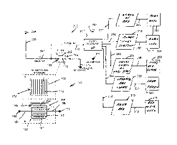
Details regarding the use of the sheet switches for functions
associated with the hospital bed 100 will now be described primarily with
respect
to FIGS. 11 and 13. FIG. 11 is a partially schematic and partially
diagrammatic
representation of the use of the sheet switches to apply signals through a
processor to initiate functions associated with the hospital bed and
surrounding
areas, in response to detection of patient movement or the detection of
obstacles
or other obstructions during mechanical movement of components of the hospital
bed 100. Turning specifically to FIG. 11, the drawing illustrates, in an
enlarged
format, one of the sheet switches 142 previously described herein. It should
be
emphasized that for the functions which will be described herein with respect
to
FIGS. 11 and 13, either of the other sheet switches 202 or 240 may also be
utilized. The sheet switch 142 is shown as being incorporated within a sheet
circuit 260 as a switch Si. The operation of the switch is identified by the
representative switch symbol 262 further shown in FIG. 11. In the circuit 260,
the
first connector 156 is shown as being connected to a voltage potential V at
terminal 264. The connection is made through a cable 266 and a resistor 268.
The resistor 268 may represent an actual resistor or the nominal resistance
which
would exist within the cable 266. It should be emphasized that cable 266 and
other elements described herein as "cables" or "lines" can be in the form of
any
suitable electrical conductors, such as ribbon cables and the like. The cables
266
and the first connector terminal 156 are also shown as being connected to an
input cable 270. Input cable 270 is further shown as applying an input signal
to a
conventional microprocessor 272. The microprocessor 272 can be any of a
number of conventional and commercially available microprocessors.
22
CA 02720861 2010-10-07
WO 2009/124397
PCT/CA2009/000480
The second connector or terminal 170 of the sheet circuit 142 is
further shown in FIG. 11 as being connected through a cable 274 to a ground
location 276. In this manner, the voltage potential V is established between
the
connectors 156 and 170, absent operation of the switch 262. It should be noted
that although various types of signals and voltage potentials are described
herein
as being designed so as to use common grounds, it would also be possible, if
desired, to utilize floating potentials, although such use can be involved
with
various electrical disadvantages.
In accordance with the foregoing description, if external forces are
applied to the sheet switch 142, a conductive path will be established between
the
connectors 156, 170. The establishment of this conductive path is represented
by
the switch 262 "closing", so as to form a conductive path between the signal
existing on cable 270 and the ground 276. The input signal therefore applied
to
the microprocessor 272 on input cable 270 would change states. The state
change will be recognized by software within the microprocessor 272.
It is apparent from the description herein that a number of sheet
switches can be associated with an individual microprocessor. Accordingly, the
microprocessor 272 may receive input signals from a number of different sheet
switches. Either through software or pursuant to hardware port connections,
software within the microprocessor 272 can be made to determine the location
of
the sheet switch which has changed states, relative to various portions of the
hospital bed 100. For example, it would be possible to utilize port
definitions or
other means so as to determine whether a change of state in a sheet switch
from
being open to being closed occurred with respect to a switch located on or
23
CA 02720861 2010-10-07
WO 2009/124397
PCT/CA2009/000480
adjacent the mattress 104. Correspondingly, it can also be determined if the
sheet switch which has changed states is located on the leg covers 118 or
caster
shields 122. Dependent upon the location of a particular sheet switch which
has
changed states from being open to being closed, functions associated with the
microprocessor 272 can cause appropriate output signals to be generated and
transmitted to various equipment associated with the hospital bed, hospital
room
and nurses station so as to perform certain functions. For example, and
continuing to refer to FIG. 11, if it was determined that the patient was
attempting
to enter or exit the bed 100, signals could be applied on output line 278
which are
shown in representative fashion as generating the process 280 which is
directed
to establishing an audio alarm at the bed 100. Either through a centralized
control
system or other similar means, signals can then be applied on line 282 as
input
signals to an audio alarm control system 284. Similarly, output signals from
the
processor 272 can be applied on line 286 so as to generate a process 288 for
generating an alarm at the nurses station. Appropriate signals can be applied
on
line 290, again as input signals to the alarm control system 284.
Still further, output signals can be generated from the processor 272
on line 292 so as to generate the process 294 of providing a visual indication
at
the nurses station. In this regard, appropriate signals can be applied on line
296
to a nurses station lighting system 298. Output signals can also be
established on
line 300 from processor 272 and applied so as to generate a process 302 of
operating lighting around the bed. In this regard, appropriate signals can be
transmitted on line 304 as input signals to a lighting control system for the
hospital
room or for the bed itself. For this particular feature, it would also be
possible for
24
CA 02720861 2010-10-07
WO 2009/124397
PCT/CA2009/000480
the processor 272 to include functions which determine whether or not there is
sufficient lighting in the hospital room so that lights do not have to operate
in
response to operation of sheet switches.
As earlier described, sheet switches in accordance with the
embodiments shown herein can be used around the lower portion of the hospital
bed so as to determine obstacles or other obstructions to raising or lowering
of the
bed 100, or other mechanical movements. If operation of a sheet switch
indicates
such an obstacle has been detected, the microprocessor 272 can apply signals
on
output line 308, so as to cause the process 310 to be established, where the
bed
100 can be made to raise a predetermined amount. For this purpose, control
signals can be applied on line 312 to a bed motor control system 314. The
signals
would be applied so as to cause the control system 314 to raise the bed the
prescribed amount.
From the foregoing description, it is clear that a number of different
functions can be performed, in response to operation of the sheet switches.
The
sheet switches could also be used to perform other functions, based upon
detection of obstacles or movement. For example, it may be possible to
position a
sheet switch in a particular location in a mattress, such that when the switch
is
activated, a sideboard adjacent the switch may be caused to be raised or
lowered.
FIG. 13 is a sequence diagram for certain functions which maybe
performed by software associated with the microprocessor 272, in response to
one or more of the sheet switches being operated so as to change states. It
should be emphasized that various types of functional sequences may be
utilized
within the software associated with processor 272.
CA 02720861 2010-10-07
WO 2009/124397
PCT/CA2009/000480
Specifically, FIG. 13 illustrates a starting or ENABLE software
location 320. At this location, an interrogation can be made of the input
ports so
as to determine if a sheet switch has changed states. If not, control is
returned to
the starting ENABLE location on control path 324. If the operation of a sheet
switch has been detected, control is transferred through path 326 to a process
328 which can determine which input line or port received the sheet switch
activation. In particular, this determination may be used to indicate the
particular
location of the sheet switch. Following this determination, control can be
transferred along control path 330 to a decision process 332, where a
determination is made as to whether the activated sheet switches are located
on
the mattress 104 or adjacent thereto. If the answer is in the affirmative,
control
can be transferred along path 334 so as to activate output signals on, for
example,
lines 278, 286 and 294 as previously described with respect to FIG. 11. These
signals would cause audible and visual alarms to be activated, in accordance
with
prior description.
Following this action, control can be transferred along path 338 to
decision process 340, where a decision is made as to whether the lighting is
sufficient within the hospital room so that it is unnecessary to activate any
other
lighting. This can be determined in a number of different ways, with various
types
of known equipment. Alternatively, a determination can be made as to the time
of
day of the switch activation, so as to determine if sunlight would be
providing
sufficient light within the room. If sufficient light is not being provided,
control can
be transferred along path 342 to a process 344, where signals are activated on
output line 300, so as to cause lights around the bed and other locations in
the
26
CA 02720861 2010-10-07
WO 2009/124397
PCT/CA2009/000480
hospital room to be activated. Following such function, control can be
returned
along path 346 to the ENABLE location 320.
If sufficient light has been determined to be available through
process 340, control can be directly transferred through path 348 back to the
ENABLE location 320. Returning to the decision process associated with the
location of the sheet switches which were operated, as determined by decision
process 332, a determination may have been made that the sheet switches are
located below the upper portion of the bed. In such event, control can be
transferred along path 350 to process 352. In this process, signals can be
activated on lines 278, 286, 292 and 308. As earlier described, signals on
line
308 will cause a process 310 (FIG. 11) to transmit signals to the motor
control
system 314 to raise the bed a predetermined amount, or otherwise undertake
other mechanical functions.
From the prior description, it is apparent that various other types of
electrical and mechanical components can be utilized with the sheet switches
and
the hospital bed 100. For example, the hospital bed 100 may have equipment
such as keypads or the like established for purposes of providing manual
activation of various functions. Such keypads can be made to be associated
with
functions initiated by operation of the sheet switches. For example, manual
functions could be provided through a keypad and associated electrical
mechanical equipment so as to provide a user with the capability of
deactivating
various alarms or other functions which have occurred as a result of operation
of
the sheet switches. Still further, it is clear that other functions could be
27
CA 02720861 2016-04-22
contemplated in response to operation of the sheet switches, beyond those
expressly described herein.
It is worthwhile emphasizing that the sheet switch as described herein can be
of
particular importance in monitoring a patient's presence with respect to the
hospital bed.
Also, and of even greater importance, the sheet switches can be used as a
method of
preventing injury to a person in or near a hospital bed, while the bed is
undergoing motorized
adjustment. In this regard, to monitor a patient's presence, activities can be
undertaken
which comprise placing a planar sheet contact switch on the bed mattress, in a
position
where it will be engaged by a person present in the bed. Still further, for
purposes of
preventing injury, the activity can include placing one or more planar sheet
contact switches
below the bed frame in positions which may consist of crush zones, where a
person would
be injured if located on the switch during bed adjustment.
It will be apparent to those skilled in the pertinent arts that other
embodiments of
sheet switches in accordance with the invention may be designed. That is, the
principles of
the claimed invention are not limited to the specific embodiments described
herein.
Accordingly, it will be apparent to those skilled in the art that
modifications and other
variations of the above-described illustrative embodiments of the invention
may be effected
without departing from the scope of the claims.
28