Note : Les descriptions sont présentées dans la langue officielle dans laquelle elles ont été soumises.
CA 02722874 2016-11-09
LOW NOx BURNER
BACKGROUND OF THE INVENTION
[00021 The present invention relates to low NO, emitting burners which are
compact,
efficient to operate, and employ furnace gas recirculation inside the
combustion chamber of
the furnace to reduce NO emissions.
[0003] Furnace emissions are of great concern because they significantly
contribute to
atmospheric pollution. A large source for NO emissions is burners as used in
large and
small furnaces, including, for example, very large furnaces used for
generating electric power
with steam-operated turbines. It is well known that NO emissions are reduced
by lowering
the temperature of the flame generated by the burner inside the furnace.
Conventionally this
has been attained by supplying the burner with excess air over what would be
required to
stoichiometrically fire the fuel, because the fuel must heat the additional
air, which lowers the
overall temperature of the flame and the furnace gases generated thereby.
[0004] Another approach to lowering NO, emissions is to mix the combustion air
for the
burner with flue gas going to the exhaust stack. This technique is called flue
gas recirculation
(FGR). Flue gas typically has a temperature in the range of between about 200
F to 400 F.
Recirculated flue gas lowers flame temperatures and NO generation, but in
excessive
amounts causes flame instability and blowout.
[00051 Both of these approaches can be used individually or in combination.
However,
large amounts of FGR that might be necessary for reducing NO, substantially
increase the
overall volume of gas that must be transported through the burner and the
furnace convection
section. This in turn requires larger blowers and conduits, including the
common windbox
outside the front wall of a burner, to handle the increased combined mass of
air and FGR with
an elevated temperature that must be transported through the system. This
increases initial
CA 02722874 2010-10-26
WO 2009/134614
PCT/US2009/040477
2
installation costs as well as subsequent operation and maintenance costs due
to the increased
energy requirements of the blower, all of which is undesirable.
[0006] As disclosed in the above-referenced, copending application, high
amounts of FGR
that must be recirculated can be reduced by recirculating furnace gases
internally of the
combustion chamber. This has worked well in reducing NO emissions and has the
advantage that it reduces or eliminates additional energy to operate a larger
blower to handle
additional combustion air and/or recirculated flue gas. The main part of the
burner disclosed
in the copending application is a massive cylindrical tube which extends from
the furnace
wall. The spinner is mounted at the discharge end of this tube. The portion of
the tube
proximate the furnace wall includes openings through which furnace gases are
aerodynamically driven by air and fuel gas jets inside the tube where the
furnace gases are
mixed with combustion air and fuel prior to the ignition of the mixture.
However, this burner
is susceptible to overheating and damage to the tube if fuel starts burning
inside the confines
of the tube. Conditions for the fuel burning inside the tube may happen when
the overall
incoming mixture of air, flue gas and fuel gas is insufficiently diluted with
inert gases like
FGR. Steering the operating regimes of the burner away from the flame burning
inside also
requires shifting more toward the discharge end of the tube that is usually
not optimal for
achieving the lowest NO emissions.
BRIEF SUMMARY OF THE INVENTION
[0007] The present invention further improves on the low NO burner described
in the
above-referenced copending patent application in that it eliminates the need
for a tube
enclosing the burner and simplifies the construction and operation of the
burner as described
below.
[0008] A low NO burner constructed in accordance with the present invention is
installed
in a furnace that has a furnace wall which encloses the combustion chamber of
the furnace.
The burner is installed on a wall of the furnace and extends through an
opening therein into
the combustion chamber, where it generates a flame.
[0009] The burner itself has a combustion air spinner that is wholly disposed
in the
combustion chamber, and its downstream end is spaced a substantial distance
from the
furnace wall, as is further described below. A combustion air tube extends
into the
CA 02722874 2010-10-26
WO 2009/134614
PCT/US2009/040477
3
combustion chamber, supports the spinner, and flows combustion air from a
combustion air
source outside the furnace through the spinner into the combustion chamber.
[0010] A plurality of air ports, preferably six, but more or less can be used,
extends from
the furnace wall into the combustion chamber. They are circumferentially
equally spaced
from each other to define spaces between them and typically supply a major
portion of the
required combustion air alone or, when needed, mixed with FGR. Their discharge
ends are
disposed inside the combustion chamber, upstream of the spinner, and they are
spaced apart
from the spinner and the furnace wall.
[0011] Suitable plates between adjacent air ports block combustion air from
flowing from
the combustion air source into the furnace except through the ports and the
pipe at the center
of the burner.
[0012] A first set of elongated fuel spuds, preferably a number of fuel spuds
which
corresponds to the number of air ports, extends from the fuel source past the
furnace wall into
the combustion chamber. Their fuel gas discharge orifices at the ends of the
spuds are spaced
from the furnace wall at least as far as the downstream end of the spinner so
that fuel gas is
discharged into the combustion chamber, where the fuel gas becomes mixed with
combustion
air from the spinner.
[0013] At least one second fuel spud is located in each pocket space between
adjacent air
ports, and extends from the fuel source past the furnace wall into the
combustion chamber.
Each second fuel gas spud is radially spaced from the axis of the burner so
that it is located
proximate a radially outermost portion of the adjacent ports. Each second fuel
spud has a
downstream end that includes one or more fuel discharge orifices disposed
inside the
combustion chamber and inside the pockets, downstream of the furnace wall and
upstream of
the discharge ends of the air ports.
[0014] The aerodynamic forces created by the second fuel jets and the air flow
discharging
through the air ports cause a circulation of combustion products (hereafter
also referred to as
"furnace gas") from the flame in the combustion chamber back to the furnace
front wall.
During this circulation the combustion products partially cool down due to the
heat transfer to
the furnace water tube walls. As a result, fuel gas propagating from second
spuds through the
space between the air ports mixes first with essentially inert reduced
temperature furnace gas.
This non-combustible mixture is further mixed with combustion air from the
discharge ends
CA 02722874 2010-10-26
WO 2009/134614
PCT/US2009/040477
4
of the air ports upstream of the spinner for the subsequent ignition of the
mixture by the
flame in the combustion chamber on the downstream side of the spinner.
[0015] The burner is further preferably associated with a fuel gas valve or
regulator that is
operatively coupled with the fuel gas source and is set to direct relatively
more fuel gas
through the second fuel gas spuds than the first fuel gas spuds.
[0016] In accordance with a presently preferred embodiment of the invention,
the burner
includes a third set of fuel gas spuds with nozzles that are disposed inside
the respective air
ports. The third fuel gas nozzles are placed along the air ports centerlines ¨
typically multiple
nozzles in each air port arranged, for example, along the radial centerline of
the air port. The
size and location of the nozzles are chosen to create an approximately uniform
distribution of
fuel with the air stream. All third nozzles inject the fuel in the same
direction as the
surrounding air streams.
[0017] The earlier-mentioned pockets between adjacent air ports are
circumferentially open
inside the combustion chamber, and neither the air tube nor the spinner are
enclosed inside a
tube or conduit so that they are in the furnace gas recirculation. This means
that furnace
gases recirculating inside the combustion chamber can enter the pockets
between adjacent air
ports, where they mix with fuel gas to form a non-combustible fuel gas/furnace
gas mixture
that flows in a downstream direction towards the spinner. Downstream of the
air port, this
mixture is further mixed with combustion air from the air ports and forms a
fuel
gas/combustion air/furnace gas mixture that can be ignited by the existing
flame downstream
of the spinner.
[0018] For specific applications it may be desired, or necessary, to deliver
to the windbox a
mixture of combustion air and FGR. This alternative is preferably limited to
applications
where particularly low NO emissions, below what can be accomplished with
furnace gas
recirculation alone, must be attained because it requires larger and therefore
more costly
blowers, ducts, windboxes, etc.
[0019] In operation following the initial lighting of the burner, the flame
generated by the
burner is anchored on the downstream end of the spinner, relatively remote
from the front
furnace wall on which the burner is mounted. Since the burner is not enclosed
inside a tube
or tubular member and the main air discharge ports are located relatively
close to the furnace
front wall, while the spinner is relatively remote from the wall and far
inside the combustion
chamber, the flow velocities of the fuel gas, combustion air and their mixture
have decreased
CA 02722874 2016-11-09
significantly by the time they reach the spinner. This avoids the problem
encountered with
typical prior art burners which are located inside and proximate the ends of
surrounding
tubular conduits where higher fuel gas-combustion air mixture velocities can
lead to flame
instabilities and relatively early flameouts when trying to achieve lowest
NO,, emissions.
5 With the burner of the present invention, the discharged air and gases
are not constrained to
limited cross-sections and, therefore, they decelerate relatively quickly,
which aids in
stabilizing the flame at the spinner. Thus, the present invention lowers the
flow velocity of
gases surrounding the spinner, increases flame stability and significantly
lowers the
likelihood of flameouts, while lower NO emissions are achieved with a burner
that is less
costly to build, install, maintain and operate than comparable prior art
burners.
[0020] In addition, by placing all fuel gas spuds inside the radially
outermost extent of the
air ports and eliminating a burner throat traditionally formed by the furnace
wall, the radial
footprint of the burner (relative to the furnace wall) is reduced so that it
occupies less space
on the burner front wall and inside the furnace chamber. This feature is
particularly
advantageous for retrofitting existing furnaces with low NO burners where size
of the
opening available for the burner is limited by the front wall water tubes
(because presently
available low NO burners are typically significantly larger than conventional
burners due to
their need for higher FGR rates and additional features needed to lower the
NO).
[0020.01] In accordance with another aspect of the present invention, there is
provided a low
NO, burner for use with a furnace having a wall and a combustion chamber
inside the wall, the
burner comprising: an elongated tube for connection to a combustion air
supply, adapted to be
installed on the wall and extending a substantial distance from the wall into
the combustion
chamber; a combustion air spinner defining an axis of the burner and connected
to the tube so
that upon installation of the tube on the wall a downstream end of the spinner
is inside the
combustion chamber and remote from the furnace wall; a plurality of elongated
air ports for
connection to the combustion air supply and adapted to extend from the wall
into the combustion
chamber, downstream discharge ends of the air ports being spaced from the
furnace wall and the
spinner; a plurality of first fuel gas spuds having fuel gas discharge
orifices in a vicinity of a
downstream end of the spinner; and a second fuel gas spud disposed between
each adjacent pair
of air ports, adapted to be connected to a fuel gas source, arranged relative
to the axis proximate
CA 02722874 2016-11-09
5a
radially outermost portions of the air ports and having fuel discharge
orifices downstream of the
furnace wall and upstream of the discharge ends.
[0020.02] In accordance with another aspect of the present invention, there is
provided a low
NO burner adapted to be installed on a furnace having a wall and a combustion
chamber inside
the wall comprising: a spinner mounted on a combustion air tube and having a
downstream end
located inside the combustion chamber at a maximum distance from the furnace
wall; at least six
elongated, spaced-apart air ports substantially equally arranged about the
tube for flowing
combustion air into the combustion chamber, each air port having a downstream
discharge end
that is spaced an intermediate distance from the furnace wall which is less
than the maximum
distance; a wall member arranged in spaces between adjacent pairs of air ports
proximate
upstream ends thereof for preventing combustion air from flowing between
adjacent air ports; a
first plurality of fuel gas discharge spuds arranged about a periphery of the
spinner and having
discharge orifices extending at least the maximum distance into the combustion
chamber; and a
second fuel gas discharge spud arranged in each space between adjacent pairs
of air ports, the
second fuel gas spud being positioned proximate radially outermost portions of
the air ports and
having a fuel gas discharge orifice for flowing fuel gas into the combustion
chamber which is
spaced from the furnace wall a minimum distance which is less than the
intermediate distance.
[0020.03] In accordance with another aspect of the present invention, there is
provided a low
NOx emitting furnace comprising: a furnace wall enclosing a combustion
chamber; a low NOx
burner with a longitudinal axis installed on the wall and extending through an
opening in the wall
into the combustion chamber, the burner generating a flame in the combustion
chamber that
generates furnace gases in the chamber which are discharged as flue gases
following a treatment
of the furnace gases; a source of combustion air and a source of fuel gas for
generating the flame;
the burner including a combustion air spinner wholly disposed in the
combustion chamber so that
a downstream end of the spinner is spaced a substantial distance from the
furnace wall; a
combustion air conduit for flowing combustion air from the source through the
spinner into the
combustion chamber; a plurality of air ports extending from the furnace wall
into the combustion
chamber and circumferentially equally spaced from each other to define spaces
between the air
ports, the air ports having discharge ends disposed inside the combustion
chamber which are
CA 02722874 2016-11-09
5b
upstream of the spinner and spaced apart from the spinner and the furnace
wall; plates between
adjacent pairs of air ports which prevent combustion air from flowing from the
combustion air
source through the spaces between the air ports; a first set of elongated fuel
spuds extending
from the fuel source past the furnace wall opening into the combustion chamber
and having fuel
gas discharge orifices which are spaced from the furnace wall at least as far
as the downstream
end of the spinner for discharging fuel gas into the combustion chamber and
mixing the fuel gas
with combustion air from the spinner; at least one second fuel spud in each
space between
adjacent air ports extending from the fuel source past the furnace wall into
the combustion
chamber, each second fuel gas spud being radially spaced from the axis so that
the second spud
is located proximate a radially outermost portion of the adjacent air ports,
each second fuel spud
having a downstream end including a fuel gas discharge orifice which is
disposed inside the
combustion chamber, downstream of the furnace wall and upstream of the
discharge ends of the
adjacent air ports so that fuel gas discharged by the second spuds mixes with
furnace gas
recirculating in the combustion chamber towards the furnace wall and into the
spaces between
adjacent air ports for forming a non-combustible fuel gas-furnace gas mixture
upstream of the
downstream ends of the air ports, the non-combustible mixture being
additionally mixed with
combustion air from the discharge ends of the air ports upstream of the
spinner for subsequent
ignition by the flame in the combustion chamber substantially downstream of
the spinner; and a
fuel gas discharge regulator operatively coupled with the fuel gas source and
the fuel gas spuds
for directing relatively more fuel gas through the second fuel gas spuds than
through the first fuel
gas spuds.
[0020.04] In accordance with another aspect of the present invention, there is
provided a method
of lowering NOx emissions from a furnace having a furnace wall, a combustion
chamber inside
the wall, a burner with a spinner located on its longitudinal axis extending
into the combustion
chamber and generating a flame inside the combustion chamber, the method
comprising
positioning the spinner in the combustion chamber so that the spinner is
located at a substantial
distance from the furnace wall, directing a first flow of combustion air
through the spinner and
discharging the combustion air from a downstream end of the spinner into the
combustion
chamber, mixing a first flow of fuel gas with the first flow of combustion air
and igniting a
resulting mixture thereof to generate the flame in the combustion chamber
downstream of the
downstream end of the spinner, arranging a plurality of separate, spaced-apart
combustion air
CA 02722874 2016-11-09
5c
streams about the first combustion air flow and discharging the combustion air
streams into the
combustion chamber, forming substantially combustion air-free pockets between
adjacent
combustion air streams upstream from where the combustion air streams are
discharged into the
combustion chamber, separately flowing a second fuel gas into the pockets in a
direction towards
the spinner, recirculating furnace gases from the combustion chamber into the
pockets, from the
pockets flowing the recirculated furnace gas towards the spinner, and
entraining the second fuel
gas flow into the recirculated combustion air in the pockets to form a fuel
gas-furnace gas
mixture, mixing the fuel gas-furnace gas mixture with the combustion air
streams upstream of
the spinner to form a combustible fuel gas/furnace gas/combustion air mixture
which flows in a
downstream direction past the spinner, and igniting the fuel gas/furnace
gas/combustion air
mixture with the flame generated downstream of the spinner.
BRIEF DESCRIPTION OF THE DRAWINGS
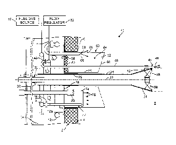
[0021] Fig. 1 is a schematic, side elevational cross-section view of a low
NO,, burner made
in accordance with the present invention, installed on a furnace wall and
taken on line I-I of
Fig. 2.
[0022] Fig. 2 is a front elevational view of the burner shown in Fig. 1.
[0023] Fig. 3 is a schematic diagram illustrating the recirculation of furnace
gases inside
the combustion chamber of the furnace in accordance with the present
invention.
DETAILED DESCRIPTION OF THE INVENTION
[0024] Referring to the drawings, a furnace 2 has a front wall 4 with an
opening 6 that
provides access into a combustion chamber 8 inside the furnace. A low NO
burner 10
constructed in accordance with the present invention extends through opening 6
into the
CA 02722874 2010-10-26
WO 2009/134614
PCT/US2009/040477
6
combustion chamber of furnace 2, where it forms a flame 84 for generating
heat. For
example, the furnace may be a boiler that generates steam.
[0025] A fuel gas supply 12 and a combustion air supply 90 are suitably
coupled to
windbox 14 attached to furnace front wall 4. The burner directs the fuel and
the combustion
air into the combustion chamber, where they are mixed, ignited and combusted,
thereby
releasing heat energy and generating high temperature furnace gases which are
typically
discharged into a convection section 16 of the furnace where temperature is
reduced,
typically to a range between about 200-400 F. The cooled flue gas is
discharged to the
atmosphere through a stack 20. As will be explained in more detail later, a
portion of the
cooled flue gas is at times recirculated into the combustion chamber via a
flue gas
recirculating system 18.
[0026] Referring now specifically to Figs. 1 and 2, burner 10 has an elongated
burner axis
22 which also is the axis of a combustion air tube 24 that is supported by a
suitable tube
mount 26 on a plate 28. An aft or upstream end 30 of the tube is open, extends
into windbox
14, and has a damper 32 which can be used to adjust the flow of combustion air
into the tube,
as is well known to those of ordinary skill in the art.
[0027] At its downstream end 34, the burner tube supports a combustion air
spinner 36
which has a downstream end with the spinner blades 38. The combustion air tube
is
sufficiently long so that the downstream end of the spinner is located at a
substantial distance
from furnace front wall 4. In one embodiment of the invention, the burner tube
has a
diameter of about 6.5 inches and the downstream end of the spinner is spaced
from the
furnace wall approximately 44 inches, so that the downstream end of the
spinner is spaced
from the furnace wall by slightly less than six times the diameter of the
tube. For most
applications, the distance between the furnace front wall and the downstream
end of the
spinner will be in the range between about four to eight times the diameter of
the combustion
air tube 24, although for particular installations and purposes and furnace
configurations this
range can be greater or less.
[0028] In the illustrated embodiment, a plurality of six center fuel gas spuds
40 are
circumferentially equally spaced about the periphery of spinner 36, they are
held in place on
the spinner by suitable spud holders 42, and their downstream ends 44 are
spaced from
furnace wall 4 at least as far as downstream end 38 of the spinner and,
preferably, they extend
slightly beyond the spinner, as is illustrated in Fig. 1. The downstream ends
of the center
CA 02722874 2010-10-26
WO 2009/134614
PCT/US2009/040477
7
spuds have orifices 46 from which fuel gas is discharged into the swirling air
flow passing
through the spinner. An upstream end 48 of each center spud is fluidly coupled
to fuel gas
source 12, shown in Fig. 1 as a circular fuel gas supply tube or manifold 12a.
[0029] In the illustrated embodiment, a plurality of six combustion air ports
50 formed by
elongated conduits are circumferentially equally spaced about combustion air
tube 24, as is
best seen in Fig. 2. Each air port is formed by radially inner and outer walls
54, 56 and side
walls 52. The cross-section of the air ports is tapered in a downstream
direction by side walls
52 so that an upstream end 58 of the air port has a larger cross-section than
a downstream
discharge end 60 thereof. The discharge end in turn is tapered (as best seen
in Fig. 1) so that
the outermost wall 56 of the air port extends further into combustion chamber
8 than the
innermost wall 54 thereof. This taper induces a bias into combustion air
flowing through the
air ports which directs the air flow towards spinner 36 for ignition by the
flame on the
downstream side of the spinner.
[0030] For typical burner constructions in accordance with the present
invention, the
spacing between furnace front wall 4 and the discharge end 60 of air ports 50
is in the range
between about one-fourth to one-half the distance between the furnace wall and
downstream
end 38 of spinner 36. In a particularly preferred embodiment of the invention,
the air port
discharge end is spaced 16 inches from the furnace wall, while the downstream
end of the
spinner is spaced 44 inches. However, these ranges can be exceeded upwardly or
downwardly should this be desirable for a given installation.
[0031] Between each adjacent pair of air ports is a radially outwardly open
space that is
closed in an upstream direction by burner plate 28 and heat insulation 62. The
spaces
between adjacent air ports form pockets 64 which are closed in an aft
direction and also
substantially in a radially inward direction and which are open in the
downstream and radially
outward directions, as can be seen in Fig. 1. As a result, effectively no
combustion air from
windbox 14 flows into or through the pockets.
[0032] Center spuds 40 extend through burner plate 28 into and past pockets 64
to the
spinner in the combustion chamber. An additional set of second fuel gas spuds
66 is arranged
close to a radially outermost portion of pockets 4 which is proximate outer
walls 56 of air
ports 50. The downstream ends of the second spuds have orifices 68. Downstream
ends of
second spuds 66 with orifices 68 are located in the combustion chamber just
downstream of
furnace wall 4 and upstream of discharge ends 60 of air ports 50 in pockets
64. Upstream
CA 02722874 2010-10-26
WO 2009/134614
PCT/US2009/040477
8
ends 70 of spuds 66 are fluidly connected to fuel source 12 in the form of a
second circular
fuel gas manifold 12b. Fuel gas exiting through orifices 68 flows into pockets
64.
[0033] A third set of fuel spuds 72 is preferably arranged inside each air
port 50 and
includes an elongated nozzle tube 74 that extends transversely to the flow
direction,
preferably along the centerline of the air port, through the air port and has
fuel gas discharge
orifices 76. An upstream end 78 of the third set of spuds 72 is fluidly
connected to fuel gas
supply 12 in the form of a third, circular fuel gas manifold 12c. Each spud 72
typically has
multiple discharge orifices 78 that are placed along the centerlines of the
air port. The size
and location of the nozzles is chosen to create an approximately uniform
distribution of fuel
in the air stream. Orifices 76 have centerlines that face in the direction of
axis 22 as is shown
on Fig. 1.
[0034] In use, combustion air flows from windbox 14 through air ports 50 past
discharge
ends 60 thereof in a downstream direction as earlier described. Gas discharge
nozzle tubes
74 in the air ports present detrimental resistance to the combustion air flow
that is
proportional to the second power of the air velocity around nozzle tubes 74.
To minimize
this resistance, tubes 74 are placed inside the ports 64 at a location where
the cross-section of
the air ports (in the plane perpendicular to axis 22) is substantially greater
than the cross-
section of the air port at discharge end 60 so that the air flow velocity past
the nozzle tubes 74
is substantially less than its velocity at the discharge end.
[0035] A pilot 80 shown on Fig. 1 is appropriately located inside at least one
of the air
ports 50 and activated for initially igniting a first portion of a combustion
air-fuel gas mixture
formed downstream of the fuel gas nozzle tube 74. The flame originated by the
pilot further
extends past the spinner discharge end 38, where it ignites the rest of the
fuel delivered to the
burner.
[0036] A fuel gas flow regulator 82 receives fuel gas from source 12, directs
controlled
quantities of the fuel gas to fuel gas manifolds 12a-c and controls the amount
of fuel gas
delivered to each of the manifolds. For typical, normal operations of the
furnace gas, the fuel
gas regulator delivers between about 5 to 20% of total fuel gas requirements
to center spuds
40, between about 30 to 70% of total gas requirements to outer spuds 66, and
between about
10 to 40% of the fuel gas requirements to the fuel gas spuds 72 inside air
ports 50.
[0037] For start-up of the furnace, burner 10 is activated by initially
blowing air from
windbox 14 into and through combustion chamber 8 of the furnace to purge the
combustion
CA 02722874 2010-10-26
WO 2009/134614
PCT/US2009/040477
9
chamber of any fuel residues that may be present. For lighting the burner, a
reduced
combustion air flow through air tube 24 and air ports 50 into the combustion
chamber is
initiated. Pilot light 80 in at least one air port 50 is lit to generate a
flame that extends
forward towards spinner 36, and fuel gas flow regulator 82 is opened to flow
fuel gas past the
orifices at the downstream ends of inner spuds 40, outer spuds 66 and spuds 72
inside air
ports 50. Thus, the pilot flame and the ignited fuel gas extend past
downstream end 38 of
spinner 36, which causes the ignition of the fuel gas emitted by all fuel gas
spuds of the
burner.
[0038] Once a flame downstream of spinner 36 is lit, pilot 80 is turned off.
The flame
extending from inside the air ports 50 to the spinner becomes extinguished due
to a lack of
flame stability inside the air ports without the presence of a sufficiently
strong pilot flame.
The operation of the burner continues with a flame 84 formed inside combustion
chamber 8
and downstream of spinner 36, fed by fuel from the spuds of the burner and
combustion air
discharged into the combustion chamber via spinner 36 and air ports 50.
[0039] The momentum of air and fuel jets coming out from discharge ends of
ports 50 and
the momentum of fuel gas jets from orifices 68 in pockets 64 cause a
recirculation 86 of
furnace gases from inner portions of the combustion chamber (downstream of
spinner 36)
towards front wall 4 of the furnace, as is illustrated in Fig. 3. The
recirculating furnace gases
are typically partially cooled from the initial flame temperature by heat
transfer to furnace
walls covered with tubes 88 normally arranged inside the furnace, e.g. along
the walls
thereof Some of the recirculating flue gas enters pockets 64 between adjacent
pairs of air
ports 50 where fuel gas from outer spuds 66 is entrained in the furnace gas.
Downstream of
air port discharge ends 60, this fuel gas/furnace gas mixture mixes with
combustion air from
air ports 50, which typically includes fuel gas from nozzle tubes 74 of the
third set of spuds
72. The furnace gas/combustion air/fuel mixture flows towards spinner 36 as
previously
described, and downstream of spinner 36 the mixture is ignited by flame 84
stabilized by the
action of the spinner 38.
[0040] The entrainment of recirculating furnace gas into the fuel
gas/combustion air
mixture results in a reduced temperature of flame 84, which in turn reduces
the generation
and emission of NO. This is advantageously attained without an increase in the
flow into
and through the furnace convection section 16 and without a need for larger
blower 92 and
CA 02722874 2010-10-26
WO 2009/134614
PCT/US2009/040477
conduit sizes that would be required if the flame temperature would be
reduced, for example,
by increasing the flow of flue gas recirculation 18.
[0041] In addition, by the time the recirculating furnace gas reaches back to
the boiler
front, it typically has a temperature of about 1000 to 2000 F. When this gas
mixes with
5 flows coming from air ports 60, it raises the overall temperature of the
resulting mixture prior
to its ignition to about 600 to 800 F. This substantially increases the ratio
between the gas
temperatures prior to and after the ignition (for a very low NO flame, its
temperature is
about 2500 F). As a result, the combustion process is more easily initiated
and maintained.
This stabilizes the flame and constitutes a significant benefit attained with
the present
10 invention.
[0042] If NO emissions need to be reduced to below what is feasible by
recirculating
furnace gas inside the combustion chamber, some of the flue gas is added to
the combustion
air via a flue gas recirculation system 18. The recirculated flue gas lowers
the available
oxygen supply in the fuel gas/combustion air/recirculated furnace gas mixture,
which leads to
a further reduction of flame temperatures and therewith the NO content of the
furnace gas
before it is discharged to the environment via flue gas treatment 16 and stack
20.
[0043] The described device allows to achieve lower minimum NO emissions with
a
stable flame than other known devices that would occupy the same overall space
on the
furnace front wall, and it is overall more energy efficient for delivering
comparable levels of
the NO emissions.