Note : Les descriptions sont présentées dans la langue officielle dans laquelle elles ont été soumises.
CA 02723316 2010-11-03
2
1066PO01 CA01
JOINING SYSTEM BETWEEN LININGS AND THE STRUCTURAL
ELEMENTS THAT SUPPORT THEM
Description
FIELD OF THE INVENTION
The present invention relates to a joining system between linings and
the structural elements that support them, particularly applicable to the
joint
between the linings and resistant structural elements of aircraft,
particularly
applicable to the aeronautical sector and in general to all those sectors
wherein linings consist of thin plates made of specific alloys or compound
materials and wherein cleanup, friction minimisation and non-perforation of
outer surfaces, due to the weakness that it originates, are desirable basic
characteristics.
BACKGROUND OF THE INVENTION
Upon analysing the types of joints currently used in the metallurgical
industry in general, these can be classified under "rivet' joints (here we
include any joint that provides a different part having a stress transmission
function between the parts to be joined) and welded joints. The good result
produced by welded joints is well known in certain industry sectors, such as
for example the naval construction sector, automotive sector, etc. However,
their applicability is reduced almost by half in the case of sectors such as
the
aeronautical sector, where the reduction of security factors and therefore the
need for full operating predictability, weight and cleanup is crucial; in
fact,
welds are hardly used in airplanes and only in internal parts with very strict
control requirements.
In the current state of the art, the thin plates that constitute the linings
of the outer fuselages of airplanes are joined to the inner structural parts
by
rivets, as they constitute the most predictable type of joint. This technique
is
used both to join the plates that form the outer linings of airplanes with the
formers and stringers that form the resistant structure of the airplane, such
as
CA 02723316 2010-11-03
3
1066PO01CA01
in wings and other surfaces, and to join the ribs with outer linings and, in
some cases, with the stringers.
As mentioned earlier, these linings consist of thin plates of aluminium
alloys or compound materials having areas along their inner surface where
they come into contact with the structural elements that support them, such
as formers and stringers, for support and fastening thereof, and with the
position of equipment and other elements and components that must be
fastened to the lining. The thin lining plates are mechanised along their
inner
surface, defining recessed areas to reduce their weight, called "bays", which
are limited by a network of ribs that constitute the aforementioned contact
areas. The internal mechanisation of the plates is generally carried out by
means of chemical milling and mechanical milling is currently being used.
At present, thin lining plates are used which are moulded into their
final aerodynamic shape by means of stretching or rolling processes, in
accordance with the type of deformation to be achieved, during which
material is recessed from those areas where it is not needed, in order to
fulfil
their structural resistance mission, through a chemical milling process. In
some assemblies with support surfaces and provided that the technique and
availability of material allow it, integral linings are used, particularly on
wing
surfaces, made of a thicker raw material that is mechanised in some cases to
obtain the aerodynamic shapes of the surfaces about five axes on one of its
sides and stringers on the other, avoiding the need for riveting. In other
cases, the integrated stringers are mechanised about three axes and the
desired shape of the part is subsequently achieved by means of a moulding
process. This effort, which evidently involves a cost, proves the importance
of avoiding rivet joints.
The decision relative to which type of lining to use in a specific case is
also conditioned by its manufacturing possibilities, the existence of raw
material, its resistant internal structure and, to a certain extent, its
production
and integration costs.
CA 02723316 2010-11-03
4
1066PO01CA01
Outer linings made of compound materials are also used in the
aeronautical industry wherein their outer shape is achieved using moulding
tools and inner shape, which is similar to metal alloy plates, by overlapping
the different fabric layers as required. These linings are also joined to the
internal structures by means of rivets. The precision achieved with this
technology requires reinforcement of certain areas, where necessary.
Rivet joints require drilling of the outer lining. The bores create a
"problem" area because it becomes fragile and can lead to the formation of
cracks, loss of pressurisation on connecting the pressurised area of the outer
part of the airplane and friction points. These parameters are vital to these
types of vehicles. In order to minimise this effect, great care must be taken
during the drilling, scarfing, countersinking and assembly processes carried
out in these types of joints, closing tolerances to the extent allowed by the
available technology, using sealants to ensure watertightness and precision
in the drill manufacturing processes and countersinking thereof, so that the
rivet heads are adequately camouflaged. All of these requirements that must
be incorporated in the design make the manufacturing and assembly work
highly meticulous, complicated and expensive.
The chemical milling technique basically consists of attacking a
surface, the thickness of which we want to reduce, with acids and protecting
those areas that we do not want to reduce by masking in order to maintain
their thickness. This attack is carried out inside a vat that contains the
acids
with controlled parameters, a component of a more complex facility, as its
application involves masking operations, trimming of the area to be treated,
cleaning, chemical attack and neutralisation for each depth that we want to
create.
While any type of linings can be manufactured based on this
technology, it is a technique that only allows mechanisation of those surfaces
parallel to the attacked face, due to which it is a technology that can only
be
used when the mechanisation of a large surface and small thickness, always
CA 02723316 2010-11-03
1066PO01 CA01
parallel, is required; additionally, it is a process that requires great
effort and,
moreover, does not fulfil the increasingly stricter environmental
requirements.
In fact, major builders have announced their intention of abandoning this type
of "milling", leading to an evolution towards mechanical milling to produce
the
5 same type of parts.
DESCRIPTION OF THE INVENTION
The object of the present invention is a joining system between the
thin plates that form the linings and structural elements that support them,
particularly in aircraft, which avoids the aforementioned drawbacks and offers
considerable advantages over traditional rivet-based joining systems.
In the system of the invention, as in the case of rivet-based joining
systems, the thin plates that constitute the linings have recessed areas or
bays in the interior thereof limited by non-recessed strips, of greater
thickness, generally straight, that determine a network of ribs positionally
coincident with the structural elements for support and fastening thereof. The
thin plates that constitute the linings will also have ribs positionally
coincident
with equipment and other components that must be fastened or related to
said linings.
The system of the invention is characterised in that the plates that
constitute the linings and structural elements include, along their opposing
surfaces, joining means between said plates and structural elements, said
joining means forming part of or being obtained from the plates and structural
elements themselves. In the system of the invention, the aforementioned
joining means consist of male and female tongue-and-groove formations,
preferably in dovetail formation. These formations have been disposed along
the contact areas between the parts to be joined. For example, in the plates
that constitute the linings, along at least part of the ribs that limit the
bays,
and in the structural elements along the sections coincident with said rib
parts.
Dovetail should be understood to be any coupling or joint formed by a
CA 02723316 2010-11-03
6
1066PO01CA01
male formation in the form of a rib and a female formation in the form of a
groove, both having the same cross-section, wherein the cross-section of the
male profile increases towards its free longitudinal edge and the cross-
section of the female profile increases downwards, in such a manner that the
coupling between the male and female formations can only be achieved
through insertion at one of its ends and sliding between the formations.
According to another characteristic of the invention, the male and
female formations of the lining plates and structural elements will be
discontinuous along the sides of the bays, determining projections and
recesses in said formations coincident in number, position and dimensions.
The male and female formations are coupled together through the opposition
and insertion of the projections of one of the formations with the recesses of
the other formation and subsequent relative longitudinal sliding between the
two formations along a length equal to that of said projections, until the
projections of the male formations are positioned behind the projections of
the female formations and the recesses of both parts are positioned in
opposition to each other.
Although the male and female formations may be indiscriminately
disposed on the lining plates or on the structural elements, the male
formations will preferably be disposed on the lining plates along the edges of
the ribs of said plates, while the female formations will be disposed on the
structural elements.
The ribs may be laterally limited by longitudinal edges having a
straight profile, generally parallel, the formations being disposed along said
longitudinal edges. The longitudinal edges may have a staggered profile, at
least along a portion adjacent to their free base, wherein the cross-section
of
the rib decreases towards said free base, whereupon the formations are
disposed along the longitudinal edges of any of the levels, preferably the
outermost level.
The formations defined by the joining means will be obtained by
CA 02723316 2010-11-03
7
1066PO01 CA01
mechanical milling of the ribs and structural elements, in the case of metal
alloy parts or, in the case of compound material parts, of metal profiles
embedded into these parts. Thanks to the advances achieved in the
mechanisation of large-scale linings, during mechanisation of the inner
surface of the plate for the formation of recessed areas or bays,
mechanisation of the corresponding formations for the dovetail joint with the
structural elements may be carried out simultaneously. The mechanisation or
recessing of the plates may also be carried out by means of chemical milling
and then shaping the male and female formations by means of mechanical
milling. In the case of linings and structural elements in composites, the
male
and female formations are disposed on profiles that are embedded into the
composite parts themselves during manufacturing thereof.
In order for the parts to maintain their final position once assembled
and to avoid longitudinal sliding between the joining means, plastic
deformations of the formations can be used, for example of the female part,
or structural adhesives or a combination of both.
Although the joining system that is the object of the present invention
is particularly applicable to the field of aeronautics, it can also be applied
to
other sectors where, as mentioned earlier, cleanup, friction minimisation and
non-perforation of outer surfaces is a desirable basic characteristic.
Additionally, the system of the invention may be applied to the joint between
the components of the structure or frame and also for fastening equipment,
components and auxiliary elements to the lining.
The system of the invention has considerable advantages over
traditional rivet-based joining systems. One of the advantages is the
decrease in friction on eliminating the rivets, which allows greater cleanup
of
the outer lining surface, while avoiding the risk of pressure leaks between
the
interior and the exterior, with pressurisation losses.
An additional advantage of the system of the invention is that on
eliminating the rivet bores the fragile points are also eliminated, in
addition to
CA 02723316 2010-11-03
8
1066PO01 CA01
improving the rest of the joint characteristics, maintaining significant
resistance to traction and ensuring its resistance to shearing.
Another advantage is the extraordinary simplification of assembly
operations on eliminating the drilling and riveting operations, also allowing
the use of lighter metallic materials. At the same time, maintenance
requirements are reduced on eliminating rivet status revision operations.
An additional advantage of the system of the invention is the reduction
in weight due to the elimination of rivets, elimination of material in
reinforcements due to the dovetail formations and recessing or crenellation
thereof and the elimination of necessary sealants in all orifices in rivet
systems. The system of the invention also allows elimination of joining parts,
such as those that transversely relate the formers.
Another additional advantage of the system of the invention is the
reduction in assembly and production costs on eliminating perforation and
rivet positioning times.
The system of the invention also allows lateral joints to be disposed
between the consecutive lining plates, when their edges are made to
coincide on a structural element, for example on a stringer or rib, whereupon
half of the male formation is disposed on each of the lining plates. As
mentioned earlier, the male and female formations are discontinuous,
defining small crenels along these, which cooperate in the reduction of
weight. A greater response to elasticity is also achieved, which represents an
advantageous solution for simplifying assembly. The dimensions of the
crenellations will depend on the requested resistance requirements and the
projections and recesses will preferably have identical plate ribs and
structural elements. In general, the recesses may be greater in length than
the projections, which will allow an additional reduction in weight.
The system of the invention is particularly applicable to aeronautics,
both to the fuselage and wings and other surfaces, such as stabilisers and
large-scale fairing. In both ribs and structural elements, shaping of the male
CA 02723316 2010-11-03
9
1066PO01 CA01
and female formations could be carried out on an auxiliary profile that would
subsequently be fastened to said ribs or structural elements. Fastening of the
auxiliary profile to the ribs could be achieved, for example, by means of
dovetail coupling, by sliding the auxiliary profile over the corresponding
formation disposed on the ribs. Fastening to the structural elements could be
carried out in the same manner or by riveting. The system of the invention
could also be used to join the composite parts, by means of mechanical
milling of the carbon fibre parts or by embedding metal parts within the
fabric
covering of the parts. For example, in the case of composite linings, the
plates may include an embedded metal profile wherein the male and female
formations would previously be disposed for dovetailing.
The system may also include male and female formations having a
coincident curved path disposed, for example, in the knots or crosspoints of
the plate ribs, and may serve to join a former, stringers and lining at one
point by means of rotation.
BRIEF DESCRIPTION OF THE DRAWINGS
The attached figures show an example of embodiment, the description
of which can help to better understand the characteristics and advantages of
the system of the invention.
In the drawings:
Figure 1 shows an inner perspective view of part of the fuselage of an
airplane wherein the plates that constitute the linings are fastened to the
structural elements using the system of the invention.
Figure 2 shows an inner perspective view of one of the lining plates.
Figure 3 shows a cross-sectional view of the fuselage, coincident with
one of the formers of the resistant structure, taken along line II-II of
figure 1.
Figure 4 shows a partial cross-section of the fuselage, taken along line
III-III of figure 3.
Figure 5 shows a partial perspective view of one of the formers of the
resistant structure.
CA 02723316 2010-11-03
1066PO01 CA01
Figure 6 corresponds to detail A of figure 5, on an enlarged scale.
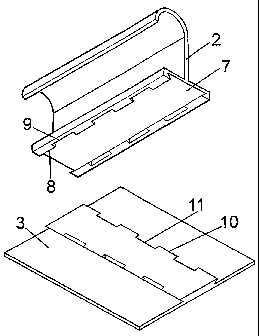
Figure 7 shows an inner perspective view of the plates that form the
lining, in the area that coincides with the former of figure 5.
Figure 8 corresponds to detail B of figure 7, on an enlarged scale.
5 Figure 9 shows an exploded perspective view of the joint between a
stringer and a lining plate.
Figure 10 shows a cross-sectional view of the projections of the male
formations of the lining plates disposed in opposition to the female
formations
of the structural elements.
10 Figure 11 shows a cross-sectional view of the recesses of the male
formations in opposition to the recesses of the female formations of the
structural elements.
Figure 12 shows a cross-sectional view, on a larger scale, of the
coupling between the male and female elements that define the joining
means between the lining plates and structural elements.
Figure 13 shows a sectional view, taken along line XIII-XlII of figure
12, of the coupling between the male and female elements of the joining
means and the opposition between the recesses of the male and female
formations.
Figure 14 shows a similar view to that of figure 9, showing the joint
between two lining plates.
Figure 15 shows a perspective view of two lining plates joined by
means of a stringer.
DETAILED DESCRIPTION OF AN EMBODIMENT
Figure 1 shows an inner perspective view of an airplane, which
includes a resistant structure composed of transverse formers 1 and
stringers 2 whereto the plates 3 of figure 2 that form a lining 3' are
fastened.
Figure 2 shows an inner perspective view of one of these plates 3,
which have recessed areas 4, called bays, limited by non-recessed strips 5
that determine a network of ribs coincident with the formers 1 and stringers 2
CA 02723316 2010-11-03
11
1066PO01 CA01
for fastening thereto. The bays 4 allow a reduction in weight of the lining
plates 3.
According to the present invention, the structural elements whereto
the lining 3' plates 3 are fastened, defined in figure 1 by the formers 1 and
stringers 2, in addition to the lining plates 3 include joining means which,
as
can be observed in figures 3 and 4, are defined by male 6 and female 7
dovetail formations. The male 6 formations will preferably form part of the
lining plates, being obtained along at least part of the ribs 5 that limit the
bays
4, without reaching the knots or crosspoints of said ribs, while the female 7
formations will be disposed on the structural elements, for example on the
formers 1 shown in figures 3 and in the stringers 2 shown in figure 9. In
addition to the formers and stringers, any type of element or equipment that
requires fastening to the lining can be fastened thereto using this invention,
shaping the corresponding parts of the male and female formations in the
contact areas of the parts to be joined. The male 6 and female 7 formations
will be discontinuous, as can be observed in figures 5 and 8, wherein the
female formations 7 determine projections 8 and recesses 9, figures 5 and 6,
while the male 6 formations of the lining plates 3 determine projections 10
and recesses 11, the projections 8 and recesses 9 of the female formations
being coincident in number, position and dimensions with the projections 10
and recesses 11, respectively, of the male 6 formations of the lining plates
3.
The male 6 formations of the lining plates 3 and female 7 formations of the
stringers 2 will adopt the same layout, as shown in figure 9.
The projections and recesses of the male and female formations
determine a crenellation wherein recesses 9 and 11 will allow a reduction in
the weight of the male and female formations. Both the male 6 and female 7
formations and recesses 9 and 11 will preferably be obtained by means of
mechanical milling, simultaneously carrying out the milling operation of the
male 6 formation and the recessing of the lining plate 3 bays 4.
In order to couple or join the lining plates 3 to the structural elements,
CA 02723316 2010-11-03
12
1066PO01 CA01
defined in the example represented in figure 1 by the formers 1 and stringers
2, the projections 10 of the male 6 formations of the lining 3' plates 3 are
disposed in opposition to the recesses 9 of the female 7 formations of the
structural elements, for example of the formers 1, as shown in figure 10,
while simultaneously disposing the recesses 11 of the male 6 formations of
the lining plates 3 in opposition to the projections 8 of the female 7
formations of the structural elements, as shown in figure 11. In this
situation,
the lining plates 3 are joined to the structural elements 1 so that the male 6
formations are introduced into the female 7 formations in the position
described in figures 10 and 11. The plates 3 are then made to longitudinally
slide against the structural elements 1, in such a manner that the projections
10 of the male 6 formations are disposed under the projections 8 of the
structural elements, as shown in figure 12, thereby completing the dovetail
joint between the lining plates 3 and the structural elements defined by the
formers 1 and stringers 2. This system allows a tight fit that practically
prevents separation or sliding between the lining plates and structural
elements. For greater security, immobilising means consisting of adhesive
substances or plastic deformations made, for example, in the female
formations or auxiliary immobilising elements such as wedges or pressure
screws, may be applied to this joint.
Figure 13 shows the final position of the projections and recesses of
the male and female formations upon being disposed in the coupling
position. The projections 10 of the male 6 formations are disposed in a
position coincident with the projections 8 of the female 7 projections and
underneath these, as described with reference to figure 12, while the
recesses 9 of the female 7 formations of the structural elements are disposed
in opposition to the recesses 11 of the male 6 formations of the lining
plates.
Although the previously described example corresponds to the joint
between the plates and structural elements of the fuselage of an airplane, the
joining system of the invention may be applied to the wing and other
CA 02723316 2010-11-03
13
1066PO01CAO1
surfaces, such as stabilisers and large-scale fairing. The joining system of
the invention may also be applied to sectors other than the aeronautical
sector, wherein, as mentioned earlier, cleanup, friction minimisation and non-
perforation of outer surfaces are desirable basic characteristics.
The system of the invention also allows lateral joints between the
lining plates 3, using the formers 1 and stringers 2, as shown in figures 14
and 15, where two lining plates 3 are disposed in abutment with each other,
each of which includes half 6' of the male 6 formations, and each of said
halves having the corresponding projections 10 and recesses 11. In this
position, the full male 6 formation is coupled to the female 7 formation of a
stringer 2, for example, in the same manner as described, whereupon the
two lining plates 3 are joined by means of the stringer or structural element
coincident with the male 6 formation.
The male 6 and female 7 formations may be shaped into auxiliary
metal profiles that are incorporated and fastened to the parts to be joined,
which will include these formations. This embodiment would be particularly
applicable when the linings and structural elements are obtained from
compound materials. The aforementioned metal profiles will be embedded, at
least partially, in the corresponding parts. The aforementioned profiles can
be obtained by means of extrusion.
As it will be understood, in order to prevent tension concentrations, all
the longitudinal angles and edges of the formations will be rounded off.