Sélection de la langue

Search

Sommaire du brevet 2724686 

Énoncé de désistement de responsabilité concernant l'information provenant de tiers

Une partie des informations de ce site Web a été fournie par des sources externes. Le gouvernement du Canada n'assume aucune responsabilité concernant la précision, l'actualité ou la fiabilité des informations fournies par les sources externes. Les utilisateurs qui désirent employer cette information devraient consulter directement la source des informations. Le contenu fourni par les sources externes n'est pas assujetti aux exigences sur les langues officielles, la protection des renseignements personnels et l'accessibilité.

Disponibilité de l'Abrégé et des Revendications

L'apparition de différences dans le texte et l'image des Revendications et de l'Abrégé dépend du moment auquel le document est publié. Les textes des Revendications et de l'Abrégé sont affichés :

  • lorsque la demande peut être examinée par le public;
  • lorsque le brevet est émis (délivrance).
(12) Brevet: (11) CA 2724686
(54) Titre français: PORTE DE BATIMENT POSSEDANT DES PROPRIETES ACCRUES DE BARRIERE CONTRE L'HUMIDITE
(54) Titre anglais: BUILDING CLOSURE WITH ENHANCED MOISTURE BARRIER PROPERTIES
Statut: Périmé et au-delà du délai pour l’annulation
Données bibliographiques
(51) Classification internationale des brevets (CIB):
  • E06B 1/62 (2006.01)
  • E04B 1/62 (2006.01)
(72) Inventeurs :
  • FURGERSON, DAVID (Etats-Unis d'Amérique)
  • GIGGS, JULIAN (Etats-Unis d'Amérique)
  • PARIKH, NIRAV D. (Etats-Unis d'Amérique)
(73) Titulaires :
  • MILGARD MANUFACTURING INCORPORATED
(71) Demandeurs :
  • MILGARD MANUFACTURING INCORPORATED (Etats-Unis d'Amérique)
(74) Agent: PIASETZKI NENNIGER KVAS LLP
(74) Co-agent:
(45) Délivré: 2013-04-30
(22) Date de dépôt: 2010-12-09
(41) Mise à la disponibilité du public: 2011-06-29
Requête d'examen: 2010-12-09
Licence disponible: S.O.
Cédé au domaine public: S.O.
(25) Langue des documents déposés: Anglais

Traité de coopération en matière de brevets (PCT): Non

(30) Données de priorité de la demande:
Numéro de la demande Pays / territoire Date
12/648,536 (Etats-Unis d'Amérique) 2009-12-29

Abrégés

Abrégé français

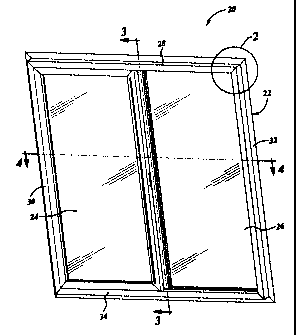
Une porte de bâtiment à installer dans une ouverture d'un mur de bâtiment comprend un cadre pour une installation dans l'ouverture de la structure du mur et au moins une porte à installer dans le cadre. Le cadre comporte au moins une enceinte intérieure s'étendant entièrement autour du cadre et une bride de clouage pour la fixation à la structure du mur du bâtiment de sorte qu'au moins une portion du cadre est disposée à l'intérieur de l'ouverture du mur du bâtiment. Il y a une cavité entre au moins une surface extérieure du cadre et la périphérie interne de l'ouverture du mur du bâtiment, et la cavité s'étend le long d'au moins une portion supérieure du cadre. Une barrière s'étend le long d'au moins la portion supérieure du cadre pour retarder le passage de l'humidité de la cavité vers l'intérieur du bâtiment. Au moins une ouverture d'évacuation de l'humidité est disposée dans la portion supérieure du cadre, à partir de la cavité vers l'espace intérieur du cadre, de sorte que cette humidité dans la cavité circule par l'ouverture d'évacuation vers l'espace, dans l'espace autour du cadre, puis vers une ouverture de drainage dans la portion inférieure du cadre.


Abrégé anglais

A building closure for mounting within an opening in a building wall structure includes a frame for mounting within the wall structure opening and at least one closure unit for mounting within the frame. The frame has at least one interior chamber extending entirely around the frame and a nailing flange for securement to the building wall structure such that at least a portion of the frame is disposed within the building wall opening. There is a cavity between at least one exterior surface of the frame and the inner periphery of the building wall opening, with the cavity extending along at least a top portion of the frame. A barrier extends along at least the top portion of the frame to retard passage of moisture from the cavity to the building interior. At least one moisture weep opening is disposed in the top portion of the frame from the cavity to the interior chamber of the frame such that moisture in the cavity flows through the weep opening into the chamber, within the chamber around the frame and then out of a drain opening in a bottom portion of the frame.

Revendications

Note : Les revendications sont présentées dans la langue officielle dans laquelle elles ont été soumises.


CLAIMS:
1. A building closure for mounting in an opening in a building wall structure,
said
closure including:
a frame for mounting within the building wall structure opening and at least
one
closure unit for mounting within said frame,
said frame having at least one interior chamber extending entirely around said
frame, and a nailing flange for securement to the building wall structure such
that at
least a portion of said frame is disposed within the building wall opening and
there is a
cavity between at least one exterior surface of said frame and an inner
periphery of the
opening extending along at least a top portion of said frame,
a barrier extending along at least said top portion of said frame to retard
passage
of moisture from said cavity to an interior of the building, and
at least one moisture weep opening in said top portion of said frame from said
cavity to said interior chamber of said frame such that moisture in the cavity
flows
through said weep opening into said chamber, within said chamber around said
frame
and then out of a drain opening in a bottom portion of said frame.
2. The closure set forth in claim 1 wherein said barrier includes a wall
extending at least
from said top portion of said frame.
3. The closure set forth in claim 2 wherein said wall comprises a flexible
wall carried
by at least said top portion of said frame for engagement with the inner
periphery of the
building wall structure opening.
7

4. The closure set forth in claim 2 wherein said wall extends at least along
top and side
portions of said frame outwardly toward the inner periphery of the building
wall
opening.
5. A building closure for mounting in an opening in a building wall structure,
said
closure including:
a frame for mounting within the wall structure opening and at least one
closure
unit for mounting within said frame,
said frame having at least one interior chamber extending around said frame,
and
a nailing flange for securement to the building wall structure such that at
least a portion
of said frame is disposed within the building wall opening and there is a
cavity between
at least one exterior surface of said frame and an inner periphery of the
building wall
opening along at least a top portion of said frame,
a seal on an inner surface of said nailing flange for engaging an opposing
surface
of the building wall structure to retard ingress of moisture into the cavity,
a barrier extending along at least said top portion of said frame to retard
passage
of moisture from the cavity to an interior of the building, and
at least one moisture weep opening in said top portion of said frame from said
cavity to said interior chamber of said frame such that moisture in the cavity
between
the seal and the barrier flows through said weep opening into said chamber,
within said
chamber around said frame and then out of a drain opening in a bottom portion
of said
frame.
6. The closure set forth in claim 5 wherein said frame comprises plural rails
each having
an exterior nailing flange segment, wherein said seal comprises a flexible
seal wall
8

secured on an interior surface of said nailing flange segments for engagement
with a
surface of the building wall structure, and wherein said barrier is secured to
an exterior
surface of at least an upper rail of said frame.
7. The closure set forth in claim 6 wherein said barrier includes a flexible
wall secured
to an exterior surface of at least upper and side rails of said frame for
engagement with
surrounding interior surfaces of the building wall opening.
8. The closure set forth in claim 6 wherein said rails are of extruded plastic
construction
and said flexible seal walls are coextruded with said rails.
9

Description

Note : Les descriptions sont présentées dans la langue officielle dans laquelle elles ont été soumises.


CA 02724686 2010-12-09
205-3076
BUILDING CLOSURE WITH ENHANCED MOISTURE BARRIER PROPERTIES
The present disclosure relates to a building closure such as a window or
sliding door,
and more particularly to an improved barrier against ingress of moisture
around the periphery of the
closure into the building interior.
Background and Summary of the Disclosure
Building closures typically include a frame for mounting within a building
wall
structure opening and at least one closure unit, such as a window or sliding
door unit, for mounting
within the frame. The frame has an exterior nailing flange for securing the
frame to the building wall
structure. Moisture can enter the cavity between the closure frame and the
surrounding wall opening
and pass into the building interior due to air pressure dynamics on the
closure. A general object of
the present disclosure is to provide a mechanism by means of which such
passage of moisture to the
building interior is retarded, and moisture is collected and drained to the
building exterior.
The present disclosure embodies a number of aspects that can be implemented
separately from or in combination with each other.
A building closure for mounting within an opening in a building wall
structure, in
accordance with one aspect of the present disclosure, includes a frame for
mounting within the wall
structure opening and at least one closure unit for mounting within the frame.
The frame has at least
one interior chamber extending entirely around the frame and a nailing flange
for securement to the
building wall structure such that at least a portion of the frame is disposed
within the building wall
opening. There is a cavity between at least one exterior surface of the frame
and the inner periphery
of the building wall opening, with the cavity extending along at least a top
portion of the frame. A
1

CA 02724686 2010-12-09
barrier extends along at least the top portion of the frame to retard passage
of moisture from the
cavity to the building interior. At least one moisture weep opening is
disposed in the top portion of
the frame from the cavity to the interior chamber of the frame such that
moisture in the cavity flows
through the weep opening into the chamber, within the chamber around the frame
and then out of
a drain opening in a bottom portion of the frame.
The barrier preferably includes a wall extending from at least the top portion
of the
frame toward the inner periphery of the building wall opening. The wall in an
exemplary
embodiment of the disclosure includes a flexible seal wall carried by at least
the top portion of the
frame for engagement with the inner periphery of the building opening. The
flexible seal wall
preferably extends along top and side portions of the frame toward the inner
periphery of the building
wall. There preferably also is a seal on an inner surface of the nailing
flange for engagement with
an opposing surface of the building wall structure to retard ingress of
moisture between the nailing
flange and the building wall structure into the cavity.
Brief Description of the Drawings
The disclosure, together with additional objects, features, advantages and
aspects
thereof, will best be understood from the following description, the appended
claims and the
accompanying drawings, in which:
FIG. 1 is a perspective view of a building closure in the form of. a sliding
window
assembly in accordance with an exemplary embodiment of the present disclosure;
FIG. 2 is an enlarged perspective view of the portion of FIG. 1 within the
area 2;
FIG. 3 is a sectional view taken substantially along the line 3 -3 of FIG.1
and showing
the window of FIG. 1 mounted within a building wall opening;
2

CA 02724686 2010-12-09
FIG. 4 is a sectional view taken substantially along the line 4-4 of FIG. 1
and showing
the window of FIG. 1 mounted within a building wall opening;
FIG. 5 is a perspective view similar to that of FIG. 2 and illustrating a
second
exemplary embodiment of the disclosure;
FIG. 6 is a sectional view similar to that of FIG.3 and illustrating the
modified
embodiment of FIG. 5; and
FIG. 7 is a fragmentary sectional view taken substantially along the line 7-7
in FIG.
2.
Detailed Description of Preferred Embodiments
FIGS. 1-4 and 7 illustrate a window assembly 20 in accordance with an
exemplary
embodiment of the disclosure as including a frame 22 and a pair of window
units 24, 26 mounted
within frame 22. In the exemplary embodiment, window unit 26 is a fixed window
unit and window
unit 24 is an operable sliding window unit. However, the present disclosure is
by no means limited
to closures of this type, but also encompasses closure assemblies such as
sliding door units, vertical
window units and a closure comprising a single fixed window unit or sash
mounted within a frame.
Frame 22 preferably comprises a plurality of rails 28, 30, 32, 34 of rigid
construction
secured end-to-end. Rails 28-34 preferably are of extruded vinyl construction,
but could be of wood,
aluminum, fiberglass or other plastic construction. Rails 28-34 can be joined
by welding mitered
ends of the rails to each other, or by other joining means known in the art
such as corner keys. In
the exemplary embodiment illustrated in the drawings, the fame 22 is of
rectangular construction.
However, non-rectangular frame constructions can be employed, such as a gable
frame having one
3

CA 02724686 2010-12-09
or more angled top rails or a radius frame having a curved top rail. Window
units for such frames
may comprise a single non-movable sash.
FIGS. 3 and 4 illustrate window 20 installed in an exemplary building wall
opening
36. Frame 22 has a nailing flange 38, which preferably extends entirely around
the frame (FIGS. 1
and 2). The nailing flange consists of several segments each integral with an
associated rail. The
nailing flange segments preferably are mitered to form a continuous flange 38
when the rails are
joined together. At least one fastener 40 (typically a plurality of fasteners)
extends through nailing
flange 38 to secure frame 22 and window 20 to the building wall structure 42
such that at least a
portion of frame 22 is disposed within opening 36. Details of wall structure
42 illustrated in FIGS.
3 and 4 (and in FIG. 6) are exemplary only. The term "nailing flange" does not
imply that fasteners
40 must be nails, and other fasteners such as screws or staples could be
employed.
With window frame 22 mounted within opening 36, a void or cavity 44 is formed
between the exterior periphery of frame 22 and at least the top and side
portions of opening 36
(FIGS. 3 and 4). As is well known in the art, exterior wind and atmospheric
dynamics create an
elevated pressure within cavity 44. In accordance with the present disclosure,
a barrier wall 46 is
carried by frame 22 around at least the top and side portions of the exterior
periphery of the frame
to retard passage of moisture from cavity 44 to the building interior. That
is, barrier wall 46 is
carried on the exterior surfaces of at least top and side rails 28, 30, 32 of
frame 22. A barrier wall
46 preferably also is carried by bottom rail 34, as best seen in FIG. 3.
Barrier wall 46 may be
relatively short since the objective is to prevent flow of moisture along the
outer surfaces of the
frame rails. However, in the illustrated embodiment, each barrier wall 46
takes the form of a flexible
resilient wall sized for opposed engagement with the surrounding inner
periphery of wall opening
4

CA 02724686 2010-12-09
36. Barrier wall 46 may be arcuate, as best seen in FIG. 7, curving outwardly
toward nailing flange
38 to facilitate insertion into window opening 36. Barrier wall 46 can be
assembled or otherwise
suitably secured to the exterior of frame 22. In the preferred embodiment of
the disclosure in which
the frame rails are of extruded plastic construction, barrier wall 46
preferably is coextruded with the
rails, and mitered and joined end-to-end as illustrated in FIG. 2. Barrier
wall 46 can be of any
suitable construction such as flexible resilient PVC.
The exemplary embodiment of FIGS. 1-4 and 7 also includes a flexible resilient
seal
wall 48 on an interior surface of nailing flange 38 for opposed engagement
with a surface of wall
structure 42 to retard ingress of moisture into cavity 44. Seal wall 48
preferably is of flexible
resilient construction such as PVC, and most preferably is coextruded with
plastic rails 28-34. Once
again, however, other techniques can be employed for securing seal wall 48 to
nailing flange 3 8.
Lower rail 34 of frame 22 includes weep (drain) openings 50 for routing
moisture to the building
exterior.
FIGS. 5 and 6 illustrate a modified window unit 54. Extruded rails 28-34
include at
least one interior chamber 56 that extends entirely around the frame from top
rail 28 through side
rails 30, 32 into bottom rail 34 (FIGS. 4 and 6). At least one moisture weep
(drain) opening 52
(FIGS. 5 and 6) is provided in the exterior wall of at least top frame rail 28
between cavity 44 and
chamber 56. Thus, any moisture that enters cavity 44 is prevented by barrier
wall 46 from flowing
to the building interior, and drains through opening 52 into chamber 56 and
then around frame 22
and out of drain openings 50 to the building exterior.
There thus has been disclosed a building closure that fully satisfies all of
the objects
and aims previously set forth. The disclosure has been presented in
conjunction with exemplary
5

CA 02724686 2010-12-09
embodiments, and modifications and variations have been discussed. Other
modifications and
variations readily will suggest themselves to persons of ordinary skill in the
art in view of the
foregoing description. The disclosure is intended to embrace all such
modifications and variations
as fall within the spirit and broad scope of the appended claims.
6

Dessin représentatif
Une figure unique qui représente un dessin illustrant l'invention.
États administratifs

2024-08-01 : Dans le cadre de la transition vers les Brevets de nouvelle génération (BNG), la base de données sur les brevets canadiens (BDBC) contient désormais un Historique d'événement plus détaillé, qui reproduit le Journal des événements de notre nouvelle solution interne.

Veuillez noter que les événements débutant par « Inactive : » se réfèrent à des événements qui ne sont plus utilisés dans notre nouvelle solution interne.

Pour une meilleure compréhension de l'état de la demande ou brevet qui figure sur cette page, la rubrique Mise en garde , et les descriptions de Brevet , Historique d'événement , Taxes périodiques et Historique des paiements devraient être consultées.

Historique d'événement

Description Date
Le délai pour l'annulation est expiré 2019-12-09
Représentant commun nommé 2019-10-30
Lettre envoyée 2018-12-10
Exigences relatives à la nomination d'un agent - jugée conforme 2014-03-27
Exigences relatives à la révocation de la nomination d'un agent - jugée conforme 2014-03-27
Inactive : Lettre officielle 2014-03-26
Inactive : Lettre officielle 2014-03-24
Demande visant la révocation de la nomination d'un agent 2014-02-24
Demande visant la nomination d'un agent 2014-02-24
Accordé par délivrance 2013-04-30
Inactive : Page couverture publiée 2013-04-29
Préoctroi 2013-02-19
Inactive : Taxe finale reçue 2013-02-19
Un avis d'acceptation est envoyé 2012-12-05
Lettre envoyée 2012-12-05
Un avis d'acceptation est envoyé 2012-12-05
Inactive : Approuvée aux fins d'acceptation (AFA) 2012-11-29
Modification reçue - modification volontaire 2012-08-28
Modification reçue - modification volontaire 2012-08-27
Inactive : Dem. de l'examinateur par.30(2) Règles 2012-02-27
Demande publiée (accessible au public) 2011-06-29
Inactive : Page couverture publiée 2011-06-28
Inactive : CIB attribuée 2011-01-20
Inactive : CIB en 1re position 2011-01-20
Inactive : CIB attribuée 2011-01-20
Inactive : Réponse à l'art.37 Règles - Non-PCT 2011-01-17
Inactive : Demande sous art.37 Règles - Non-PCT 2011-01-11
Inactive : Certificat de dépôt - RE (Anglais) 2011-01-10
Exigences de dépôt - jugé conforme 2011-01-10
Lettre envoyée 2011-01-10
Demande reçue - nationale ordinaire 2011-01-10
Exigences pour une requête d'examen - jugée conforme 2010-12-09
Toutes les exigences pour l'examen - jugée conforme 2010-12-09

Historique d'abandonnement

Il n'y a pas d'historique d'abandonnement

Taxes périodiques

Le dernier paiement a été reçu le 2012-10-30

Avis : Si le paiement en totalité n'a pas été reçu au plus tard à la date indiquée, une taxe supplémentaire peut être imposée, soit une des taxes suivantes :

  • taxe de rétablissement ;
  • taxe pour paiement en souffrance ; ou
  • taxe additionnelle pour le renversement d'une péremption réputée.

Les taxes sur les brevets sont ajustées au 1er janvier de chaque année. Les montants ci-dessus sont les montants actuels s'ils sont reçus au plus tard le 31 décembre de l'année en cours.
Veuillez vous référer à la page web des taxes sur les brevets de l'OPIC pour voir tous les montants actuels des taxes.

Historique des taxes

Type de taxes Anniversaire Échéance Date payée
Enregistrement d'un document 2010-12-09
Taxe pour le dépôt - générale 2010-12-09
Requête d'examen - générale 2010-12-09
TM (demande, 2e anniv.) - générale 02 2012-12-10 2012-10-30
Taxe finale - générale 2013-02-19
TM (brevet, 3e anniv.) - générale 2013-12-09 2013-11-14
TM (brevet, 4e anniv.) - générale 2014-12-09 2014-11-14
TM (brevet, 5e anniv.) - générale 2015-12-09 2015-11-13
TM (brevet, 6e anniv.) - générale 2016-12-09 2016-11-10
TM (brevet, 7e anniv.) - générale 2017-12-11 2017-11-14
Titulaires au dossier

Les titulaires actuels et antérieures au dossier sont affichés en ordre alphabétique.

Titulaires actuels au dossier
MILGARD MANUFACTURING INCORPORATED
Titulaires antérieures au dossier
DAVID FURGERSON
JULIAN GIGGS
NIRAV D. PARIKH
Les propriétaires antérieurs qui ne figurent pas dans la liste des « Propriétaires au dossier » apparaîtront dans d'autres documents au dossier.
Documents

Pour visionner les fichiers sélectionnés, entrer le code reCAPTCHA :


Pour visualiser une image, cliquer sur un lien dans la colonne description du document. Pour télécharger l'image (les images), cliquer l'une ou plusieurs cases à cocher dans la première colonne et ensuite cliquer sur le bouton "Télécharger sélection en format PDF (archive Zip)" ou le bouton "Télécharger sélection (en un fichier PDF fusionné)".

Liste des documents de brevet publiés et non publiés sur la BDBC .

Si vous avez des difficultés à accéder au contenu, veuillez communiquer avec le Centre de services à la clientèle au 1-866-997-1936, ou envoyer un courriel au Centre de service à la clientèle de l'OPIC.


Description du
Document 
Date
(aaaa-mm-jj) 
Nombre de pages   Taille de l'image (Ko) 
Dessins 2010-12-08 6 199
Description 2010-12-08 6 240
Revendications 2010-12-08 4 95
Abrégé 2010-12-08 1 28
Dessin représentatif 2011-05-29 1 15
Dessins 2012-08-26 6 560
Revendications 2012-08-26 3 82
Dessins 2012-08-27 6 510
Revendications 2012-08-27 3 84
Dessin représentatif 2013-04-11 1 37
Accusé de réception de la requête d'examen 2011-01-09 1 178
Courtoisie - Certificat d'enregistrement (document(s) connexe(s)) 2011-01-09 1 103
Certificat de dépôt (anglais) 2011-01-09 1 157
Rappel de taxe de maintien due 2012-08-12 1 111
Avis du commissaire - Demande jugée acceptable 2012-12-04 1 163
Avis concernant la taxe de maintien 2019-01-20 1 181
Correspondance 2011-01-09 1 22
Correspondance 2013-02-18 3 127
Correspondance 2014-02-23 4 114
Correspondance 2014-03-13 31 986
Correspondance 2014-03-23 1 14
Correspondance 2014-03-25 1 27