Note : Les descriptions sont présentées dans la langue officielle dans laquelle elles ont été soumises.
CA 02724705 2010-11-17
WO 2009/140760 PCT/CA2009/000688
ARTIFICIAL STONE
FIELD OF THE INVENTION
The present invention relates to surface coverings and artificial stones for
forming
a surface covering. More particularly, the invention relates to stones,
flagstones, pavers,
bricks, veneer blocks and tiles for forming surface coverings, such as
walkways,
roadways, pavements or wall coverings.
BACKGROUND OF THE INVENTION
It is well known in the art that surfaces, such as walkways, driveways,
patios,
floors, work surfaces, walls and other interior or exterior surfaces can be
covered for
durability and aesthetics with flagstones, stones, bricks, pavers, tiles and
other
architectural surface covering elements. Natural stone surface coverings are
constructed by
fitting together irregularly sized and shaped flat stones, such as flagstone,
stone and slate.
This work requires a skilled stonemason to select, cut and fit the stones. It
is labor
intensive, and accordingly expensive. To minimize installation time, the
stonemason uses
a combination of large stones or slabs, for achieving as much surface coverage
in as short
a time as possible, and a collection of small stones, so called filler stones,
for filling in any
gaps between the irregularly shaped large stones.
Various efforts have been made to develop artificial building elements, such
as
bricks, stones, flagstones, pavers, or the like with the appearance of natural
stone. Such
artificial building elements are usually relatively inexpensively mass
produced by molding
them from concrete, usually in a dry casting operation. They are typically
provided in
geometric shapes, such as triangles, squares, rectangles and hexagons, or in
irregular
shapes, or combinations thereof. The goal is to provide units of preset shape,
which can be
placed side by side in mating arrangement to produce a continuous surface
covering.
However, even if irregularly shaped stones are used, the repetitive nature of
the
installation usually results in a repeating, sometimes even geometric pattern,
or at least a
`linear line effect'. This counteracts any `natural' appearance of the overall
surface
covering, despite the almost `natural' appearance of the individual elements.
Furthermore,
even irregularly shaped stones with randomly placed simulated joints embossed
into their
facing surface, when laid out in mating arrangement still produce a repeating
pattern, since
the overall shape of the stones becomes apparent from the pattern of the
perimeter joints
1
CA 02724705 2010-11-17
WO 2009/140760 PCT/CA2009/000688
around the stones, once multiple stones are laid out in a repeating pattern.
Thus, these
stones still fail to provide an aesthetically pleasing appearance with a
degree of natural
irregularity close to that of custom installations of natural stone.
Thus, there still exists a need for an artificial stone, flagstone, paving
stone or the
like which upon installation in a mating array with like artificial stones
provides the
appearance of a natural stone installation with large slabs and intermediate
small filler
stones.
SUMMARY OF THE INVENTION
Throughout the description, the expressions `stone' and `flagstone' are used
interchangeably without distinction and to designate any blocks, stones,
flagstones, paving
stones, pavers, siding bricks or blocks, veneer bricks, and the like.
Therefore, the
expressions "artificial stone" and "artificial flagstone" should be given
their broadest
possible meaning and should be interpreted to encompass any and all artificial
stone
elements for forming any surface covering.
The term "artificial" is used throughout this specification to designate any
non-
naturally occurring product.
The term "regular" as used in relation to the geometric shape of various parts
of the
artificial stone in this specification is used to define a regular geometric
shape.
The term "simulated joint" as used in this specification describes all
structures
which penetrate the facing surface of an artificial stone to divide the facing
surface into
surface portions. The simulated joints preferably extend only through a
portion of the
height of the artificial stone, so that when the unit is installed, they
provide the appearance
of a regular joint between individual stones, giving the visual impression of
an
arrangement of smaller subunits. The simulated joints preferably are
sufficiently deep to
retain the joint filler material used for installation of the artificial
stones, such as sand or
mortar, but do not affect the integrity of the stone during normal handling
and installation.
The term "perimeter recess" is used throughout this specification to describe
a recess, cut-
away, or notch along the outer edge of the artificial stone, which extends
into the body of
the stone from the perimeter and up to the surface of the stone to create the
appearance of
a cut-away or notch in the body of the stone at the perimeter. The perimeter
recess gives
the artificial stone the appearance of a natural stone having peripheral shape
imperfections
and results in a gap between the stone and another like stone placed in
engagement
2
CA 02724705 2010-11-17
WO 2009/140760 PCT/CA2009/000688
therewith. Since the perimeter recess extends into the body from the
perimeter, the gap is
wider then the adjoining perimeter joint.
The overall appearance of a mating array of artificial flagstones varies
depending
on the degree of subdivision of the facing surface of the individual stones.
However, even
when artificial flagstones with mutually different surface subdivisions are
used, once they
are arranged in a regular array, a discernible repeating pattern appears,
irrespective of the
surface subdivisions of the individual stones. This is due to the perimeter
joints between
the stones forming a regular, repeating pattern, since all the stones have the
same body
shape. It has now been surprisingly discovered that even a repeating pattern
of flagstones
of substantially identical body shape can be made to have a substantially
random or
natural appearance. This can be achieved by not only dividing the facing
surface of the
individual stones by one or more simulated joints to provide the appearance of
a large
stone or slab and one or more adjacent and smaller filler stone, but by
further providing
the stones with a perimeter recess. The natural appearance effect becomes
especially
apparent when the facing surface is designed to include a major area free of
any
subdividing, simulated joints so that the resulting artificial stone has a
facing surface
including a major surface area free of any simulated joints and having the
appearance of a
slab. It has been surprisingly discovered that even when artificial stones in
accordance
with the invention are installed in a repeating installation pattern with
intermediate
perimeter joints, a substantially random or natural appearance is generated by
the inclusion
of the perimeter recess. Including one or more recesses in one or more stones
in the
repeating pattern, preferably in each stone, results in one or more holes or
gaps in the
surface covering produced by the mating array, which gaps are then filled with
sand,
mortar or like filler material after placement of the artificial stones to
form the surface
covering. These gaps appear identical to gaps found in arrangements of natural
stones due
the shape mismatch of natural stones. Most importantly, those gaps are
provided to
interrupt the perimeter joints between adjoining stones and to thereby break
up the
perimeter joint pattern in an array of like stones arranged in a repeating
installation
pattern. The resulting overall appearance of the surface covering of
artificial stones of the
invention is then one of a multitude of larger stones, intermediate smaller
stones and joints
between the stones, with some joints widening out into the gaps formed by the
perimeter
recesses. Each gap is preferably larger than the adjoining perimeter joint and
at most 5
times as large as the perimeter joint.
3
PCT/CA2009/000688
CA 02724705 2010-11-17 19 March 2010 19-03-2010
In one preferred aspect, the present invention provides an artificial
flagstone for
covering a supporting surface, which flagstone includes a body with a facing
surface and
base surface for placement on the supporting surface. The body has an overall
body shape
with a polygonal body contour which defines the footprint of the stone. The
facing surface
has a total surface area defined by a facing contour. The facing surface is
subdivided by at
least one simulated joint into a major surface portion and at least one minor
surface
portion. The major surface portion is continuous and free of simulated joints,
extends over
at least about 60% of the total surface area and has the appearance of a slab,
while the
minor surface portion has the appearance of a filler stone.
In another preferred aspect of the invention, the major surface portion
extends over at least
about 65%, preferably at least about 68%, most preferably at least about 70%
of the total
surface area.
In still another preferred aspect of the invention, the major surface portion
extends
over at least about 75%, preferably at least about 80% of the total surface
area, most
preferably at least about 85%.
In a further preferred aspect of the invention, the minor surface portion
extends
over at most about 30% of the total surface area and is free of simulated
joints.
In still a further preferred aspect of the invention, the surface area is
divided into a major
surface portion and a pair of minor surface portions, the combined area of the
minor
surface portions being at most about 30% of the total surface area.
Preferably, the surface
area is divided into a major surface portion and a plurality of minor surface
portions, the
combined area of the minor surface portions being at most about 35%,
preferably at most
about 30%, most preferably at most about 25% of the total surface area and the
simulated
joints cover at most about 5% of the total surface area.
In yet a further preferred aspect of the invention, the major surface portion
of the
facing surface extends over at least 70% of the footprint of the stone, the
minor surface
portion extends over at least 15% of the footprint, the simulated joints cover
at most 5% of
the footprint and the perimeter recesses cover at most 10% of the footprint.
Artificial flagstones in accordance with the invention for covering a
supporting
surface preferably include a polygonal footprint and a body shaped as a right
prism for
mating engagement of the flagstone with like flagstones in an array or
repeating
installation pattern for producing a surface covering.
4
AMENDED SHEET
CA 02724705 2010-11-17
WO 2009/140760 PCT/CA2009/000688
Preferably, the facing surface has a facing contour fitting within the
footprint of the
body. The facing surface preferably has a surface structure with the
appearance of natural
stone. The contour of the facing surface is preferably irregular for enhancing
the natural
appearance of the stone. To further enhance the natural appearance, the facing
surface
preferably has at least one irregularly shaped protrusion or depression for
giving the facing
surface the appearance of natural stone. More preferably, the facing surface
has at least
one irregularly shaped protrusion and at least one irregularly shaped
depression.
Most preferably, the perimeter recess extends from the facing surface all the
way
to the base surface so that a gap or hole is formed between the flagstone and
an adjacent,
mating flagstone. The gap preferably has a width which is larger then the
width of the
adjoining perimeter joint. The perimeter recess can be placed anywhere along
the
perimeter of the artificial stone, but is preferably placed at a corner of the
flagstone, or
adjacent an end of a simulated joint to further enhance the natural appearance
of a surface
covering of mating flagstones in accordance with the invention.
Artificial stones in accordance with the invention are preferably made by dry
casting and the perimeter recess is preferably made by a division plate used
in the dry cast
mold. In a variant, the facing surface has at least two areas of different
elevation, which
areas are preferably irregularly shaped areas.
In another aspect of the invention, the artificial stone is breakable along at
least one
of the simulated joints. This allows breaking off one or more of the minor
surface portions,
while still rendering possible a mating engagement of the broken artificial
stone with other
like units, either complete or broken off, and provides greater flexibility
for size
adjustment during installation. The simulated joints may in some locations
extend all the
way to the base surface of the artificial stone to facilitate breaking off of
the minor surface
portion, as long as this does not affect the integrity of the stone during
normal handling
and installation.
In a further preferred aspect of the invention, the artificial stone is shaped
and
constructed as a paving stone. The artificial stone of the invention is
preferably made by
dry casting and is most preferably is a dry cast paving stone.
In still another preferred aspect, the invention provides a set of artificial
stones for
producing a surface covering in a regular, repeated pattern, but with an
irregular surface
appearance, simulating the appearance of natural stone. The set includes at
least two
flagstones with a body of polygonal cross-section and shaped as a right prism
to fit
5
CA 02724705 2010-11-17
WO 2009/140760 PCT/CA2009/000688
together in a mating arrangement, and an irregularly shaped facing surface.
The facing
surface of one flagstone in the set is different in appearance from the facing
surface of
every other flagstone in the set and especially differs in the placement
and/or number of
the simulated joints and the placement and/or number of the perimeter recess
regions.
Preferably, the set of flagstones includes all the stones made within a multi-
cavity dry
casting frame, whereby each cavity produces a stone with a different facing
surface.
BRIEF DESCRIPTION OF THE DRAWINGS
Other objects and advantages of the invention will become apparent upon
reading
the detailed description and upon referring to the drawings in which:
FIG 1 is a top plan view of an artificial stone in accordance with the
invention;
FIG 2 is a schematic view of the stone shown in FIG 1;
FIG 3 is a top plan view of another artificial stone in accordance with the
invention;
FIG 4 is a schematic view of the stone shown in FIG 3;
FIG 5 is a top plan view of a further artificial stone in accordance with the
invention;
FIG 6 is a schematic view of the stone shown in FIG 5;
FIG 7 is a top plan view of still another artificial stone in accordance with
the
invention;
FIG 8 is a schematic view of the stone shown in FIG 7;
FIGs 9a to 9g are schematic views of different artificial stones, each having
a
major surface portion covering 70% or more of the facing surface;
FIG 10 is a simulated top plan view of a surface covering arrangement using
artificial stones as shown in FIGs 9a to 9g;
FIG 11 is a simulated perspective view of a surface covering arrangement using
artificial stones as shown in FIGs 9a to 9g;
FIGs 12a to 12d are schematic views of different artificial stones with
rectangular
base, each having a major surface portion covering 70% or more of the facing
surface; and
FIG 13 is a simulated perspective view of a surface covering arrangement using
artificial stones as shown in FIGs 12a to 12d;
FIGs 14a to 14i are schematic views of different artificial stones of a shape
similar
to those shown in FIGs 9a to 9g, each stone having a polygonal base portion
and facing
6
CA 02724705 2010-11-17
WO 2009/140760 PCT/CA2009/000688
surface of irregular, polygonal outline fitting within the polygonal outline
of the base
portion;
FIG 15 is a simulated perspective view of a surface covering arrangement using
artificial stones as shown in FIGs 14a to 14g;
FIGs 16a to 16d are schematic views of artificial stones with a right
rectangular
base portion and a top portion with a facing surface of an irregular outline
fitting within
the rectangular outline of the base portion;
FIG 17 is a simulated perspective view of a surface covering arrangement using
artificial stones as shown in FIGs 16a to 16d;
FIGs 18a to 18c show schematic isometric views of artificial stones with a
generally hexagonal footprint and a facing surface divided into a major
surface portion
covering at least 70% of the facing surface and one or more minor surface
portions and
FIGS 18d to 18f show the same stones, but having at least one perimeter
recess;
FIG 19 is a simulated perspective view of a surface covering arrangement using
artificial stones as shown in FIGs 18d to 18f, illustrating the gaps between
the mating
stones created by the perimeter recesses;
FIGs 20a to 20d are schematic isometric views of artificial stones with a
right
rectangular base portion and a top portion with a facing surface of an
irregular outline
fitting within the rectangular footprint of the base portion and FIGs 20e to
20h show the
same stones, but having at least one perimeter recess;
FIG 21 is a simulated perspective view of a surface covering arrangement using
artificial stones as shown in FIGs 20e to 20h, illustrating the gaps between
the mating
stones created by the perimeter recesses;
FIG 22 is a simulated top view of the surface covering arrangement of FIG 21;
FIGs 23a to 23d are schematic isometric views of artificial stones with a
right
triangular base portion and a top portion with a facing surface of an
irregular outline fitting
within the triangular footprint of the base portion and FIGs 23e to 23h show
the same
stones, but having at least one perimeter recess;
FIG 24 is a simulated top view of a surface covering arrangement using
artificial
stones as shown in FIGs 23e to 23h, illustrating the gaps between the mating
stones
created by the perimeter recesses; and
FIGs 25a and 25b are schematic illustrations of artificial stones in
accordance with
the invention with hexagonal and rectangular footprint, respectively and
illustrating the
7
PCT/CA2009/000688
CA 02724705 2010-11-17 19 March 2010 19-03-2010
areas of the footprint covered by the major surface portion, the minor surface
portion, the
simulated joints an the perimeter recesses.
DETAILED DESCRIPTION OF PREFERRED EMBODIMENTS
Before explaining the present invention in detail, it is to be understood that
the
invention is not limited to the preferred embodiments contained therein. The
invention is
capable of other embodiments and of being practiced or carried out in a
variety of ways. It
is to be understood that the phraseology and terminology employed herein are
for the
purpose of description and not of limitation.
The present invention provides artificial stones, flagstones, bricks, pavers,
tiles and
the like for forming surface coverings, such as pavements, walkways or wall
coverings,
having the appearance of a natural stone covering.
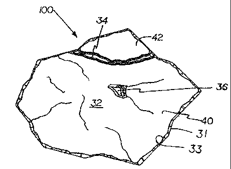
A preferred artificial stone 100 in accordance with the invention as shown in
FIGs.
I and 2, includes a body 110 having a facing surface 32 on the body and a base
surface 19
for placement on a supporting surface (not shown). The body 110 has a body
shape with a
body contour 31 defining a footprint of the body 110 and, thus, the stone 100.
The facing
surface 32 has a facing contour 33 and a total surface area defined by the
facing contour
33, which area is divided by at least one simulated joint 34 into a major
surface portion 40
and one or more minor surface portions 42, 43, 44, 45. The minor surface
portions are
preferably located at the facing contour 33. The simulated joints 34 are
preferably
irregular in appearance and width and have irregular edges. The major surface
portion 40
is free of any simulated joints 34 and extends over at least about 60% of the
facing surface
and has the appearance of a continuous slab, and the minor surface portion has
the
appearance of a filler stone. As is apparent from FIG. 1, the facing contour
33 fits into the
body contour 31 or footprint of the body 110.
The major surface portion preferably extends over about 65% of the total
surface
area, more preferably at least 70%, even more preferably at least 75%, most
preferably
about 80%.
The facing surface 32 preferably has a polygonal facing contour 33. The
simulated
joints 34 are preferably positioned to divide off one or more points of the
polygonal facing
surface 32 (FIGS. 1-4). When more than one simulated joint 34 is provided,
(FIGs. 5-8),
each joint can be positioned to divide off a separate minor portion 42, 43,
respectively
located at different corners or points of the facing surface (FIGs. 7 and 8).
Alternatively,
8
AMENDED SHEET
CA 02724705 2010-11-17
WO 2009/140760 PCT/CA2009/000688
one simulated joint 34 can be used to divide off a minor portion 42 at one
corner or point
of the facing surface 32 and one or more additional simulated joints 34 can be
used to
subdivide this minor portion 42 into multiple minor portions 43, 44.
The simulated joints 34 preferably extend through a portion of the height of
the
stone 100, so that when the stone is laid out, it gives the visual impression
of an
arrangement of smaller units, while still retaining the advantages of handling
only a larger
block. In another aspect of this embodiment, the joints 34 can be sufficiently
deep so that
the artificial stone 100 may be breakable along the joints 34. This allows
breaking off a
section of the stone, while still rendering possible a mating engagement of
the broken
stone with other ones. The simulated joints 34 may in some locations extend
all the way to
a base surface 19 of the artificial stone to facilitate the breaking off, as
long as this does
not affect the integrity of the stone during normal handling and installation.
A preferred artificial stone 100 in accordance with the invention as
illustrated in
FIG. 2 includes a base portion 10 with a base surface 19 for placement on a
supporting
surface (not shown), for example a wall or a walkway. The base portion 10 is
shaped for
mating engagement of the stone with like stones in a repeated, mating
arrangement to
produce a surface covering of stones with intermediate perimeter points (see
FIG 10). In
the illustrated embodiment, the base portion 10 of the stone 100 has a
polygonal footprint
similar to a hexagon. It is readily understood that footprints of other
geometric shape, such
as triangular, square, rectangular, octagonal, or the like can be used as long
as they allow
the stone 100 to engage like stones in a mating arrangement or repeating
installation
pattern. The stone 100 further includes a top portion 30 with a facing surface
32 having a
natural appearance and a facing contour 33 with a depending rim 39. An
intermediate
portion 50 connects the rim 39 with the base portion 10.
The intermediate portion 50 preferably has at least one circumferential
portion
which it is outwardly tapered. The intermediate portion 50 preferably has at
least one
sidewall 52 extending between the rim 39 and a sidewall 11 of the base portion
10 and
joining the base portion sidewall 11 and the rim 39 at an acute angle of 0 to
25 . This
construction greatly facilitates the dry casting operation by ensuring an even
distribution
of the concrete mix and, thus, an even fill of the mold. Damage to the freshly
molded
stone during stripping and disengagement from the mold due to sharp corners in
the mold
and adhesion to mold surfaces is also minimized with this construction.
9
PCT/CA2009/000688
CA 02724705 2010-11-17 19 March 2010 19-03-2010
In the embodiments shown in FIGs 1 to 8, 11, 13, 15, 17, 18a-18f, 19, 20a-h
and
21 the base portion 10 has the basic shape of a right prism. This basic
structure allows the
manufacture of a large number of stones with base portions 10, which easily
fit together in
a mating arrangement, but have significantly differing top portions 30 and
facing surfaces
32. It not only allows for the formation of a reliable and durable surface
covering by
arranging the stones in a regular pattern, but at the same time provides for
great variability
in appearance of the facing surface 32, resulting in an irregular and natural
appearance of
the covering due to the differently shaped top portions 30, as will be
apparent from the
covering arrangements shown in FIGs 10, 13, 15, 17, 19, 21 and 22. It will be
readily
apparent that the base portion 10 can have any other shape which allows the
stone to be
fitted with other stones in accordance with the invention into a mating
arrangement
forming a surface covering. For example, the base portion 10 may have a
square,
rectangular, pentagonal, hexagonal, triangular, or irregular polygonal outline
or footprint
and may be in the shape of a right prism. The base portion 10 may also include
spaces (not
shown) along the perimeter or body contour 31 of the stone in order to widen
the
perimeter joints and provide improved drainage between the stones.
The artificial stone 100 is preferably manufactured by dry casting. The facing
contour 33 of the facing surface 32 preferably fits into and is located above
the footprint of
the base portion 10 (see FIGs 1, 14-17, 20, 21) to enable stripping of the
stone 100 from
the mold in a dry casting operation. Furthermore, the depending rim 39 is
preferably
oriented perpendicular to a base surface 19 of the body 110 and the base
portion 10. This
facilitates dry casting of differing artificial flagstones, since facing
surfaces 32 of different
appearance and facing contour 33 can be produced with the same mold frame by
simply
changing the compression shoe of the dry casting mold. The depending rim 39
ensures
proper alignment and fit of the shoe and avoids damage to the molded stone
during
stripping from the mold.
The outline or facing contour 33 of the facing surface 32 is preferably
irregular for
achieving a natural appearance. To further enhance the natural appearance of
the top
portion 30, the facing surface 32 preferably has at least one irregularly
shaped protrusion
35 or depression 36 (see FIGs. land 2) for giving the top portion 30 the
appearance of
natural stone. More preferably, the facing surface 32 has at least one
irregularly shaped
protrusion 35 and at least one irregularly shaped depression 36. In a variant,
the facing
AMENDED SHEET
PCT/CA2009/000688
CA 02724705 2010-11-17 19 March 2010 19-03-2010
surface has at least two areas of different elevation, which areas are
preferably irregularly
shaped areas.
To avoid the generation of the "linear line effect" often observed with
regularly
shaped artificial stones in the art, especially those with a polygonal facing
surface, the
stone 100 of the present invention is preferably provided with a facing
surface 32 which is
unevenly divided by one or more simulated joints to provide the appearance of
a large
stone and a small stone.
The exemplary artificial flagstones shown in FIGs 1-22 are shaped and
constructed
as paving stones, preferably produced in a dry casting mold. However, it is
readily
apparent that the artificial stones of the invention can be used as other
floor or wall
coverings. FIGs 9a to 9f show a set of artificial stones 100 in accordance
with the
invention. Each illustrated artificial stone 100 in accordance with the
invention includes a
body 110 and a facing surface 32 on the body. The facing surface 32 has a
facing contour
33, which defined a total surface area of the facing surface. The facing
surface is divided
by at least one simulated joint 34 into a major surface portion 40 and one or
more minor
surface portions 42, 43, 44, 45 located at the facing contour 33. The major
surface portion
40 is continuous and free of simulated joints 34 and extends over at least
about 60% of the
facing surface to give it the appearance of a slab. The minor surface portion
has the
appearance of a filler stone, or multiple filler stones, giving the artificial
stone the overall
appearance of a large slab stone combined with one or more filler stones.
The facing surface 32 preferably has a polygonal facing contour 33. The
simulated
joints 34 are preferably positioned to divide off one or more points or
corners of the
polygonal facing surface 32. When more than one simulated joint 34 is
provided, (FIGs.
9a-9e, 9f), each joint can be positioned to divide off a separate minor
surface portion 42,
43, respectively located at different corners or points of the facing surface
(FIGs. 9a-9e,
9f). Alternatively, one simulated joint 34 can be used to divide off a minor
surface portion
42 at one corner or point of the facing surface 32 and one or more additional
simulated
joints 34 can be used to subdivide this minor surface portion 42 into multiple
minor
surface portions 43, 44, 45 (FIGs. 9d, 9e, 9f). It is also within the confines
of the invention
to subdivide the minor surface portion 42 into multiple minor surface portions
(43, 44, 45)
by a plurality of simulated joints 34, whereby one or more of the minor
surface portions
are no longer located at the facing contour 33 (see portion 45 in FIG. 9f).
11
AMENDED SHEET
PCT/CA2009/000688
CA 02724705 2010-11-17 19 March 2010 19-03-2010
FIGs. 10 and 11 show an arrangement of artificial stones 100 in accordance
with
the invention resulting in a surface covering with an irregular surface,
simulating the
appearance of natural stone. Thanks to its particular configuration, when an
artificial stone
100 according to the invention is used in combination with other like ones,
for defining a
surface covering, each stone 100 is matingly engageable with neighboring
stones 100. The
set shown in FIGs. 10 and 11 includes multiple stones 100 with base portions
shaped to fit
together in a mating arrangement, producing a continuous surface covering. In
the
illustrated arrangement of FIGs. 10 and 11, each stone 100 is advantageously
provided
with a facing surface 32 having a texture that imitates a natural artificial
stone, such as a
natural flagstone. Due to the differing surface structures of the stones 100
and especially
the combination on the surface of each stone of a major, slab like surface
portion with one
or more minor, filler stone like surface portions, the overall surface of the
surface covering
has an irregular, natural appearance.
FIGs 12a to 12d show a set of artificial stones 100 in accordance with the
invention. Each illustrated artificial stone 100 in accordance with the
invention includes a
body 110 in the shape of a right rectangular prism and a facing surface 32 on
the body.
The facing surface 32 has a facing contour 33 and a surface area and is
divided by at least
one simulated joint 34 into a major surface portion 40 and one or more minor
surface
portions 42, 43, 44, 45,46 located at the facing contour 33. The major surface
portion 40 is
free of simulated joints 34 and extends over at least about 60% of the total
surface area of
the facing surface and has the appearance of a slab. The minor surface portion
has the
appearance of a filler stone, or multiple filler stones, giving the artificial
stone the overall
appearance of a large slab stone combined with one or more filler stones.
In this embodiment, the facing surface 32 has a substantially rectangular
facing
contour 33. The simulated joints 34 are positioned to divide off one side of
the rectangular
facing surface 32. When more than one simulated joint 34 is provided, (FIGs.
12a-12d),
the simulated joints can be positioned to sub-divide the cut-off minor portion
42 along the
side of the facing contour 33. Two or more simulated joints 34 can be used to
divide off
the minor portion 42 and to subdivide it into multiple minor portions 43, 44,
45, 46 (FIGs.
12a-12d). It is also within the confines of the invention to subdivide the
minor portion 42
into multiple sub-portions (43, 44, 45, 46) by a plurality of simulated joints
34, whereby
one or more of the sub-portions are no longer located at the facing contour 33
(see portion
45 in FIG. 12c).
12
AMENDED SHEET
PCT/CA2009/000688
CA 02724705 2010-11-17 19 March 2010 19-03-2010
FIG. 13 shows an arrangement of artificial stones 100 of substantially
rectangular
contour in accordance with the invention resulting in a surface covering with
an irregular
surface, simulating the appearance of natural stone. Thanks to its particular
configuration,
when an artificial stone 100 according to the invention is used in combination
with other
like ones, for defining a surface covering, each stone 100 is matingly
engageable with
neighboring stones 100. The set shown in FIG. 13 includes multiple stones 100
with base
portions shaped to fit together in a mating arrangement, producing a
continuous surface
covering. Each stone 100 has a top surface texture that imitates a natural
artificial stone,
such as a natural flagstone. Due to the differing surface structures of the
stones 100 and
especially the combination on the surface of each stone of a major, slab like
surface
portion (40) with two or more, filler stone like, minor surface portions (42,
43, 44, 45, 46),
the overall surface of the surface covering has an irregular, natural
appearance.
FIGs 14a to 14i show a set of artificial stones 100 in accordance with the
invention
and similar to those shown in FIGs. 9a to 9f. However, each artificial stone
100 illustrated
in FIGs. 14a to 14i includes a body 110 with a polygonal body contour 31
defining a
footprint of the stone and a facing surface 32 of a polygonal contour
different from the one
of the body, but fitting within the footprint of the body. This principle
relationship
between the shape of the facing surface 32 and the body was previously
discussed in
relation to FIGs. 1 to 8. As with the artificial stones shown in FIGs 9a to
9f, the facing
surface 32 has a facing contour 33 and a surface area and is divided by at
least one
simulated joint 34 into a major surface portion 40 and one or more minor
surface portions
42, 43, 44, 45, 46, 47 located at the facing contour 33. The major surface
portion 40 is free
of simulated joints 34 and extends over at least about 60% of the facing
surface and has
the appearance of a slab. The minor surface portion has the appearance of a
filler stone, or
multiple filler stones, giving the artificial stone the overall appearance of
a large slab stone
combined with one or more filler stones.
The facing surface 32 preferably has a polygonal facing contour 33. The
simulated
joints 34 are preferably positioned to divide off one or more points or
corners of the
polygonal facing surface 32. When more than one simulated joint 34 is
provided, (FIGs.
14a-f and 14h), each joint can be positioned to divide off a separate minor
surface portion
42, 43, respectively located at different corners or points of the facing
surface.
Alternatively, one simulated joint 34 can be used to divide off a minor
surface portion 42
at one corner or point of the facing surface 32 and one or more additional
simulated joints
13
AMENDED SHEET
PCT/CA2009/000688
CA 02724705 2010-11-17 19 March 2010 19-03-2010
34 can be used to subdivide this minor surface portion 42 into multiple minor
surface
portions 43, 44, 45 (FIGs. 14c and 14f). It is also within the confines of the
invention to
subdivide the minor surface portion 42 into multiple minor surface portions
(43, 44, 45) by
a plurality of simulated joints 34, whereby one or more of the minor surface
portions are
no longer located at the facing contour 33 (see portion 45 in FIG. 14f).
FIG. 15 shows an arrangement of artificial stones 100 in accordance with the
invention resulting in a surface covering with an irregular surface,
simulating the
appearance of natural stone. Thanks to its particular configuration, when an
artificial stone
100 according to the invention is used in combination with other like ones,
for defining a
surface covering, each stone 100 is matingly engageable with neighboring
stones 100. The
set shown in FIG. 15 includes multiple stones 100 with base portions shaped to
fit together
in a mating arrangement, producing a continuous surface covering. In the
illustrated
arrangement, each stone 100 is advantageously provided with a facing surface
32 having a
texture that imitates a natural artificial stone, such as a natural flagstone.
Due to the
differing surface structures of the stones 100 and especially the combination
on the surface
of each stone of a major, slab like surface portion with one or more minor,
filler stone like
surface portions, the overall surface of the surface covering has an
irregular, natural
appearance.
FIGs 16a to 16d show a set of artificial stones 100 in accordance with the
invention
and similar to those shown in FIGs. 12a to 12d. However, each artificial stone
100
illustrated in FIGs. 16a to 16d includes a body 110 with a rectangular body
contour 31 or
footprint and a facing surface 32 of a contour different from the one of the
body contour,
but fitting within the footprint of the body. This principle relationship
between the shape
of the facing surface 32 and the body was previously discussed in relation to
FIGs. 1 to 8
and 14a to 14i. As with the artificial stones shown in FIGs 12a to 12d, the
facing surface
32 has a facing contour 33 and a surface area and is divided by at least one
simulated joint
34 into a major surface portion 40 and one or more minor surface portions 42,
43, 44, 45,
46, preferably located at the facing contour 33. The major surface portion 40
is free of
simulated joints 34 and extends over at least about 60% of the total facing
surface and has
the appearance of a slab. The minor surface portion has the appearance of a
filler stone, or
multiple filler stones, giving the artificial stone the overall appearance of
a large,
continuous slab stone combined with one or more filler stones.
14
AMENDED SHEET
PCT/CA2009/000688
CA 02724705 2010-11-17 19 March 2010 19-03-2010
The facing surface 32 preferably has an irregular, but overall substantially
rectangular facing contour 33. The simulated joints 34 are preferably
positioned to divide
off one or more points or corners of the polygonal facing surface 32. When
more than one
simulated joint 34 is provided, each joint can be positioned to divide off a
separate minor
surface portion 42, 43, respectively located at different corners, sides or
points of the
facing surface. Alternatively, one simulated joint 34 can be used to divide
off a minor
surface portion 42 along one side of the facing surface 32 and one or more
additional
simulated joints 34 can be used to subdivide this minor surface portion 42
into multiple
minor surface portions 43, 44, 45. It is also within the confines of the
invention to
subdivide the minor surface portion 42 into multiple minor surface portions
(43, 44, 45) by
a plurality of simulated joints 34, whereby one or more of the minor surface
portions are
no longer located at the facing contour 33 (see FIG. 16b).
FIG. 17 shows an arrangement of artificial stones 100 in accordance with the
invention resulting in a surface covering with an irregular surface,
simulating the
appearance of natural stone. Thanks to its particular configuration, when an
artificial stone
100 according to the invention is used in combination with other like ones,
for defining a
surface covering, each stone 100 is matingly engageable with neighboring
stones 100. The
set shown in FIG. 17 includes multiple stones 100 with base portions shaped to
fit together
in a mating arrangement, producing a continuous surface covering. In the
illustrated
arrangement, each stone 100 is advantageously provided with a facing surface
32 having a
texture that imitates a natural artificial stone, such as a natural flagstone.
Due to the
differing surface structures of the stones 100 and especially the combination
on the surface
of each stone of a major, slab like surface portion with one or more minor,
filler stone like
surface portions, the overall surface of the surface covering has an
irregular, natural
appearance.
In a particularly preferred embodiment, as illustrated in FIGs. 18 to 22, the
invention provides an artificial stone 200 including a polygonal base portion
210 of a
preselected body contour or footprint 270 which allows for mating engagement
along the
perimeter of the stone in a repeated pattern with other like stones. The
preselected body
contour 270 of the base portion 210 is selected such that the stones when
arranged in
mating engagement are closely spaced along their perimeter to adjacent stones
with
intermediate perimeter joints between the stones. Apart from the base portion
210, the
stones of FIGs 18 to 22 include a facing surface 232 having a natural
appearance and a
AMENDED SHEET
CA 02724705 2010-11-17
WO 2009/140760 PCT/CA2009/000688
facing contour 233 with a depending sidewall 211. The facing surface 232 has a
surface
area and is divided by at least one simulated joint 34 into a major surface
portion 40 and
one or more minor surface portions 42, 43, 44, 45 located at the contour 233.
The preselected body contour 270 or footprint of the artificial stones of
FIGs. 18a
to 18f is similar to the one of the stones shown in FIGs. 1 to 11, 14 and 15.
However, as is
apparent from a comparison of the stones shown in FIGs. 18a to 18c (which are
identical
to those of FIGs. 9b, 9f and 9e) with those of FIGs. 18d to 18f, the
artificial stones in
FIGs. 18d to 18f are additionally provided with one or more perimeter recess,
cut-way or
setback 260. Each perimeter recess 260 extends into the body of the stone 200
and
represents a region along the perimeter of the artificial stone 200 at which
the outer edge
or sidewall 211 of the stone is set back from the preselected body contour or
footprint 270
of the base portion 210. In FIGs. 18d to 18f, the preselected body contour is
shown as a
broken line in the regions of the perimeter recess 260. Each perimeter recess
260 creates
the appearance of a portion of the outer edge or sidewall 11 having been cut
or broken
away or the stone having peripheral shape imperfections. In other words,
artificial stones
200 in accordance with the invention as shown in FIGs 18d to 18f have regions
along their
perimeter where the outer edge or sidewall 11 of the artificial stone is set
back from the
preselected body contour or footprint 270 so that exact mating engagement of
the stone
200 with a like stone is no longer possible in those regions, since the
perimeter recess 260
results in a gap 280 between the adjoining individual stones, as is apparent
from FIG. 19.
The gaps 280 significantly enhance the natural appearance of a repeated
pattern of the
artificial stones 200, since the gaps provide a break in the perimeter joints
and visually
break the pattern of juncture lines between the stones, the perimeter joints,
especially
when all perimeter joints 285 (see FIG. 21) between the stones 200, the
simulated joints 34
and the gaps 280 are filled with sand, grout or the like to complete the
installation of the
stones. Each gap 280 is wider than the adjoining perimeter joint 285.
Preferably, the peripheral recesses 260 extend over the full height of the
artificial
stone 200 as shown in FIGs. 18d to 18f, to enhance the natural appearance of
the stone.
Although it is also possible to provide the peripheral recesses 260 over only
a part of the
height of the artificial stone 200, they preferably extend to a sufficient
depth from the
facing surface 232 to prevent exposure of the base portion 210 of the stone
200 should
some of the fill material in the gaps 280 (sand, grout or the like) be washed
out or
otherwise lost.
16
CA 02724705 2010-11-17
WO 2009/140760 PCT/CA2009/000688
FIGs 20a to 20h show a set of artificial stones 200 in accordance with the
invention
and similar to those shown in FIGs. 18a to 18f. However, each artificial stone
200
illustrated in FIGs. 20a to 20h includes a base portion 210 with a polygonal
body contour
270, or footprint, and a facing surface 232 of a polygonal facing contour 233
different
from the one of the base portion 210, but fitting within the body contour or
footprint 270.
This principle relationship between the shape of the facing surface 232 and
the shape of
the body and its footprint was previously discussed in relation to FIGs. 1 to
8 and 14a to
14i. As with the artificial stones shown in FIGs 18a to 18f, the facing
surface 232 has a
contour 233 and a surface area and is divided by at least one simulated joint
34 into a
major surface portion 40 and one or more minor surface portions 42, 43, 44, 45
located at
the facing contour 233.
Similar to the stones of FIGs. 18d to 18f, the artificial stones 200 of FIGs.
20e to
20h are respectively provided with one or more perimeter recess or setback
260. Each
perimeter recess 260 represents a region along the perimeter of the artificial
stone 200 at
which the outer edge or sidewall 211 of the stone is set back from the
preselected body
contour 270 of the base portion 210. As in FIGs. 18d to 18f, the preselected
body contour
270 is shown in FIGs. 20e to 20h as a broken line in the regions of the
perimeter recesses
260. This results in gaps 280 between the individual stones at the location of
the perimeter
recesses 260, when the stones 200 are arranged side-by-side, as is apparent
from FIGs. 21
and 22. The gaps 280 which significantly enhance the natural appearance of a
repeated
pattern of the artificial stones 200, as is clearly apparent from FIG. 22.
When the perimeter
joints 285 (see FIG. 21) between the stones 200, the simulated joints 34 and
the gaps 280
are filled with sand, grout or the like to complete the installation of the
stones, the filled
gaps visually break the pattern of juncture lines between the stones, which
surprisingly
results in a very natural overall appearance of the installed stones, despite
the stones all
having the same preselected contour and being arranged in a repeated pattern.
FIG. 22 simulates the appearance of a regular pattern of the stones 200 from
FIGs.
20e to 20h with the fill material in the perimeter joints 285, simulated
joints 34 and gaps
280 being shown in grey. The resulting overall appearance is very natural and
emulates a
combination of large, slab like stones of irregular shape with small filler
stones of irregular
shape.
FIGs 23a to 23h show a set of artificial stones 200 in accordance with the
invention
and similar to those shown in FIGs. 18a to 18f. However, each artificial stone
200
17
PCT/CA2009/000688
CA 02724705 2010-11-17 19 March 2010 19-03-2010
illustrated in FIGs. 23a to 23h includes a base portion 210 with a triagonally
shaped body
contour 270, or footprint, and a facing surface 232 of a polygonal facing
contour 233
different from the one of the base portion 210, but fitting within the body
contour or
footprint 270. This principle relationship between the shape of the facing
surface 232 and
the shape of the body and its footprint was previously discussed in relation
to FIGs. 1 to 8
and 14a to 14i. As with the artificial stones shown in FIGs 18a to 18f, the
facing surface
232 has a facing contour 233 and a surface area and is divided by at least one
simulated
joint 34 into a major surface portion 40 and one or more minor surface
portions 42, 43, 44,
45 located at the facing contour 233. Similar to the stones of FIGs. 18d to
18f, the artificial
stones 200 of FIGs. 23e to 23h are respectively provided with one or more
perimeter
recess or setback 260. Each perimeter recess 260 represents a region along the
perimeter
of the artificial stone 200 at which the outer edge or sidewall 211 of the
stone is set back
from the preselected body contour 270 of the base portion 210. As in FIGs. 18d
to 18f, the
preselected body contour or footprint 270 is shown in FIGs. 23e to 23h as a
broken line in
the regions of the perimeter recesses 260. This results in gaps 280 between
the individual
stones at the location of the perimeter recesses 260, when the stones 200 are
arranged side-
by-side, as is apparent from FIG. 24. The gaps 280 which significantly enhance
the natural
appearance of a repeated pattern of the artificial stones 200, as is clearly
apparent from
FIG. 24. When the perimeter joints 285 between the stones 200, the simulated
joints 34
and the gaps 280 are filled with sand, grout or the like to complete the
installation of the
stones, the filled gaps visually break the pattern of juncture lines or
perimeter joints
between the stones, which surprisingly results in a very natural overall
appearance of the
installed stones, despite the stones all having the same preselected contour
and being
arranged in a repeated pattern.
FIG. 24 simulates the appearance of a regular pattern of the stones 200 from
FIGs.
23e to 23h with the fill material in the perimeter joints 285, simulated
joints 34 and gaps
280 being shown in grey. The resulting overall appearance is very natural and
emulates a
combination of large, slab like stones of irregular shape with small filler
stones of irregular
shape.
FIG. 25a and 25b schematically illustrate artificial stones 200 in accordance
with
the invention with hexagonal and square footprint 270 respectively. The areas
of the
footprint covered by the major surface portion 40, the minor surface portions
42, 43, 44,
the simulated joints 34 and the perimeter recesses 260 are respectively
identified. It is
18
AMENDED SHEET
CA 02724705 2010-11-17
WO 2009/140760 PCT/CA2009/000688
preferred that, as is apparent from FIGs. 18d-18f, 20e-20h and 23e-23h, the
major surface
portion 40 covers preferably at least about 70% of the footprint 270, the
minor surface
portions 42, 43, 44 cover preferably at least about 15% of the footprint, the
simulated
joints 34 preferably cover at most 5% of the footprint and the perimeter
recesses 260
preferably cover at most about 10% of the footprint.
In another aspect, the invention provides a set of artificial stones, wherein
the top
surface texture of each stone in the set is different from the top surface
texture of every
other stone in the set. Such a set of stones preferably includes all the
stones made within a
multi-cavity dry casting frame, whereby each cavity produces one stone with a
facing
surface that is unique within the set. The base portions of the stones in the
set preferably
have a polygonal cross-section and are shaped as a right prism so that the
base portions fit
together in a mating arrangement of the flagstones in the set and flagstones
of other like
sets.
In a preferred method in accordance with the invention, the set of artificial
stones
is made in a dry casting operation using a multi-cavity mold having a tamper
shoe with a
differently shaped compression surface for each cavity in the mold to produce
a different
surface texture for the artificial stone made in each cavity. The method
preferably includes
the steps of providing a multi-cavity dry casting frame, each mold cavity of
the dry casting
frame having sidewalls for shaping the body of the artificial stone, at least
one division
plate in the dry casting frame separating adjacent cavities having a
protrusion for
extending into one cavity and forming a perimeter recess in a sidewall of the
dry cast stone
made in the cavity, placing the multi-cavity dry casting frame on a press
support, filling
the mold cavity with a dry cast concrete mixture and compressing the dry cast
concrete
mixture with the tamper shoe having a different surface structure for each
mold cavity,
stripping the compressed pre-product from the mold cavity, and curing the
stripped pre-
product to form the set of artificial stones. In a preferred embodiment, the
method
includes the step of replacing the division plate in the dry casting frame
having the
protrusion with a division plate having one or more different protrusions to
form one or
more different perimeter recesses in the dry cast artificial stones.
From the above, it can easily be understood that the artificial stone
according to the
present invention can advantageously be used for creating patios, pathways,
sidewalks or
stepping stones for non-limitative examples. Moreover, the artificial stone of
the present
invention can advantageously be easily laid out to form a pavement or a wall
surface
19
CA 02724705 2010-11-17
WO 2009/140760 PCT/CA2009/000688
where no straight lines and hardly any repetition can be seen, giving as a
result, the look of
old world craftsmanship, replicating the complexity of a natural stone
assembly.
Furthermore, it will be appreciated that all of the artificial stone of a
pavement can
be the same, but still create a visually "random" effect in which no straight
lines can be
seen.
The artificial stone according to the present invention has several advantages
over
prior art products. Indeed, its installation is very easy, does not require
distinctive markers
for guiding the installation, and does not require professional skills. The
resulting
pavement has no "linear effect", that is, a person walking thereon would not
see any
straight line in front of him or her. It has a random look, achieved with a
single stone
design.
While the invention has been described with a certain degree of particularity,
it is
understood that the invention is not limited to the embodiments set forth
herein for
purposes of exemplification, but is to be limited only by the scope of the
attached claims,
including the full range of equivalency to which each element thereof is
entitled.
Although the present invention has been explained hereinabove by way of
preferred embodiments thereof, it should be pointed out that any modifications
to these
preferred embodiments within the scope of the appended claims are not deemed
to alter or
change the nature and scope of the present invention.