Sélection de la langue

Search

Sommaire du brevet 2725160 

Énoncé de désistement de responsabilité concernant l'information provenant de tiers

Une partie des informations de ce site Web a été fournie par des sources externes. Le gouvernement du Canada n'assume aucune responsabilité concernant la précision, l'actualité ou la fiabilité des informations fournies par les sources externes. Les utilisateurs qui désirent employer cette information devraient consulter directement la source des informations. Le contenu fourni par les sources externes n'est pas assujetti aux exigences sur les langues officielles, la protection des renseignements personnels et l'accessibilité.

Disponibilité de l'Abrégé et des Revendications

L'apparition de différences dans le texte et l'image des Revendications et de l'Abrégé dépend du moment auquel le document est publié. Les textes des Revendications et de l'Abrégé sont affichés :

  • lorsque la demande peut être examinée par le public;
  • lorsque le brevet est émis (délivrance).
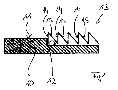
(12) Demande de brevet: (11) CA 2725160
(54) Titre français: CACHE ET PROCEDE DE REVETEMENT DE COMPOSANTS
(54) Titre anglais: COVERING DEVICE AND METHOD FOR COATING COMPONENTS
Statut: Réputée abandonnée et au-delà du délai pour le rétablissement - en attente de la réponse à l’avis de communication rejetée
Données bibliographiques
(51) Classification internationale des brevets (CIB):
  • B05D 1/10 (2006.01)
(72) Inventeurs :
  • JAKIMOV, ANDREAS (Allemagne)
  • SCHNEIDERBANGER, STEFAN (Allemagne)
  • HERTTER, MANUEL (Allemagne)
(73) Titulaires :
  • MTU AERO ENGINES GMBH
(71) Demandeurs :
  • MTU AERO ENGINES GMBH (Allemagne)
(74) Agent: MILLMAN IP INC.
(74) Co-agent:
(45) Délivré:
(86) Date de dépôt PCT: 2009-05-26
(87) Mise à la disponibilité du public: 2009-12-03
Licence disponible: S.O.
Cédé au domaine public: S.O.
(25) Langue des documents déposés: Anglais

Traité de coopération en matière de brevets (PCT): Oui
(86) Numéro de la demande PCT: PCT/DE2009/000720
(87) Numéro de publication internationale PCT: WO 2009143817
(85) Entrée nationale: 2010-11-22

(30) Données de priorité de la demande:
Numéro de la demande Pays / territoire Date
10 2008 025 510.6 (Allemagne) 2008-05-28

Abrégés

Abrégé français

L'invention concerne un cache (13) pour le revêtement de composants par compression cinétique à froid ou par projection cinétique de gaz à froid, ledit cache permettant de recouvrir une zone (12) de la surface du composant (10) ne devant pas être revêtue. Selon l'invention, le cache (13) est profilé de manière à former avec la zone (12) de la surface qu'il doit recouvrir et qui n'est donc pas à revêtir, un angle aigu de manière que les particules d'un matériau de revêtement peuvent être déviées du composant (10) et n'adhèrent pas au cache (13).


Abrégé anglais


The invention relates to a covering device (13) for the coating of components
via
cold kinetic compaction or kinetic cold gas spraying, which can be used to
cover a
region (12) which is not to be coated of a surface of the component (10) which
is to
be coated. According to the invention, the covering device (13) is profiled
such that it
encloses such an acute angle with that region (12) of the surface which is to
be
covered by same and therefore is not to be coated, that particles of a coating
material can be deflected from the component (10) such that said particles do
not
adhere to the covering device (13).

Revendications

Note : Les revendications sont présentées dans la langue officielle dans laquelle elles ont été soumises.


Claims
1. Covering device for the coating of components via cold kinetic compaction
or
kinetic cold gas spraying, which can be used to cover a region which is not to
be
coated of a surface of the component which is to be coated,
characterized in that
the covering device is profiled such that it encloses such an acute angle with
that region of the surface which is to be covered by same and therefore is not
to be
coated, that particles of a coating material can be deflected from the
component
such that said particles do not adhere to the covering device.
2. Covering device according to Claim 1,
characterized in that
said covering device is profiled in a zigzag shape.
3. Covering device according to Claim 1 or 2,
characterized in that
first sections (14) of the covering device (13) enclose a right angle with the
region of the surface which is not to be coated, and that second sections (15)
of the
covering device, which are respectively positioned between the two first
sections
(14), enclose a smaller angle of at least 30°.
4. Covering device according to Claim 1 or 2,
characterized in that
first sections (17) of the covering device (16) enclose an angle between 300
and 900 with the region of the surface which is not to be coated, and that
second
sections (18) of the covering device, which are respectively positioned
between two
first sections (17), enclose a smaller angle of at least 30°.
5. Covering device according to Claim 4,
characterized in that
depressions (19) configured between the first sections (17) and the second
sections (18) are covered so that no particles of the coating material reach
said
depressions.

6. Covering device according to one of Claims 1 to 5,
characterized in that
said covering device is formed of a metallic material.
7. Covering device according to one of Claims 1 to 5,
characterized in that
said covering device is formed of a hard plastic.
8. Method for coating components of a turbomachine, in particular a gas
turbine,
wherein a coating material is applied for forming the coating via cold kinetic
compaction or kinetic cold gas spraying on a surface of the component,
characterized in that
a region of the surface which is not to be coated is covered with a covering
device (13; 16) according to Claims 1 to 7.
6

Description

Note : Les descriptions sont présentées dans la langue officielle dans laquelle elles ont été soumises.

CA 02725160 2010-11-22
COVERING DEVICE AND METHOD FOR COATING COMPONENTS
[001] The invention relates to a covering device for the coating of components
via
cold kinetic compaction according to the pre-characterizing clause of Claim 1
and a
method for coating components via cold kinetic compaction according to the pre-
characterizing clause of Claim 8.
[002] Coating components of a turbomachine via cold kinetic compaction or
kinetic
cold gas spraying is already known from practice, wherein, in this case, a
coating is
applied to a to-be-coated component in that particles of a coating material
are
directed at a to-be-coated surface of the component that is being coated with
the aid
of a carrier gas. In this connection, a flat coating of the surface of the
component
being coated is always being carried out.
[003] Then, if only sections of a component are supposed to coated, i.e., if a
region
of the surface of the component being coated is supposed to be coated and
another
region of the surface of the component being coated is not supposed to be
coated,
the not-to-be-coated region of the surface of the to-be-coated component must
be
covered with the aid of a covering device. Covering devices, which can be used
to
cover the regions of the surface that are not to be coated, are already known
for
coating methods such as thermal spraying. These covering devices for thermal
spraying that are known from the prior art are not suitable, however, for use
when
coating components via cold kinetic compaction. Thus, the covering devices
known
from practice would themselves be coated and had to be disposed of after the
coating process.
[004] Starting herefrom, the object of the present invention is creating a
novel
covering device for the coating of components via cold kinetic compaction or
kinetic
cold gas spraying and a method for coating components.
[005] This object was attained by a covering device according to Claim 1.
According
to the invention, said covering device is profiled such that it encloses such
an acute
angle with that region of the surface which is to be covered by same and
therefore is
1

CA 02725160 2010-11-22
not to be coated, that particles of a coating material can be deflected from
the
component such that said particles do not adhere to the covering device.
[006] The covering device according to the invention is suitable especially
for the
coating of sections of components via cold kinetic compaction or kinetic cold
gas
spraying. Thus, in the case of the covering device according to the invention,
there is
no danger that said covering device itself will be coated by the coating
material. As a
result, it is possible to use the covering device according to the invention
as
frequently as desired. This makes economical, sectional coating of components
via
cold kinetic compaction possible. As already mentioned, covering devices that
have
been adapted true-to-contour can be used multiple times.
[007] The method according to the invention is defined in Claim 8.
[008] Preferred further developments of the invention are disclosed in the
subordinate claims and the following description. Without being limited
hereto,
exemplary embodiments of the invention will be explained in more detail on the
basis
of the drawing. The drawing shows:
[009] Fig. 1 a first embodiment of a covering device according to the
invention for
the coating of components via cold kinetic compaction or kinetic cold gas
spraying;
and
[0010] Fig. 2 a second embodiment of a covering device according to the
invention
for the coating of components via cold kinetic compaction or kinetic cold gas
spraying.
[0011]The present invention relates to the coating of components, particularly
components of a gas turbine, via cold kinetic compaction or kinetic cold gas
spraying.
[0012] In the case of cold kinetic compaction or kinetic cold gas spraying,
particles of
a coating material are applied to form the coating on the component with the
aid of a
carrier gas, namely on a to-be-coated surface of the component.
2

CA 02725160 2010-11-22
[0013] Fig. 1 shows a rough diagram of a component 10 to be coated via cold
kinetic
compaction or kinetic cold gas spraying, wherein the to-be-coated component 10
is
supposed to be coated in a first region 11 of a surface and not to be coated
in a
second region 12 of the surface.
[0014]The region 12 of the surface of the component 10 that is not supposed to
be
coated can be covered with a covering device 13 according to the invention,
wherein
the inventive covering device 13 is profiled such that it encloses such an
acute angle
with that region 12 of the surface of the component which is to be covered by
same
and therefore is not to be coated, that particles of a coating material can be
deflected
from the component 10 such that the particles do not adhere to the covering
device
13.
[0015]According to Fig. 1, to this end, the covering device 13 is profiled in
a zigzag
shape, wherein first sections 14 enclose a right angle with the not-to-be-
coated
region 12 of the surface of the component 10, and wherein second sections 15
of the
covering device 13, which are respectively positioned between two adjacent
first
sections 14, enclose a smaller angle with the not-to-be-coated region 12 of
the
surface of the component 11, which is at least 30 , however. This makes it
possible
to guarantee that particles of a coating material, which are directed at the
surface of
the component 10 at a right angle, ricochet off the second sections 15 of the
covering device 13 according to the invention and are thereby deflected from
the
component 10. Neither the not-to-be-coated region 12 of the surface of the
component 11 nor the covering device 13 are coated in the process so that it
is
possible to use said covering device as frequently as desired.
[0016] In order to avoid damage to the covering device 13 from the high
particle
velocity during cold kinetic compaction, said covering device is fabricated of
a hard
material, e.g., of a metallic material or a hard plastic.
[0017] Fig. 2 shows the to-be-coated component 10 with a covering device 16
according to a second exemplary embodiment of the present invention, wherein
the
covering device 16 is profiled in turn in a zigzag shape just like the
covering device
13. In the case of the covering device 16 in Fig. 2, said covering device has
first
3

CA 02725160 2010-11-22
sections 17, which enclose an angle of between 30 and 90 with the not-to-be-
coated region 12 of the surface of the component. Second sections 18, which
are
positioned respectively between two adjacent first sections 17 of the covering
device
13, enclose a smaller angle with the not-to-be-coated region 12 of the surface
of the
component 10, namely an angle of at least 30 .
[0018] This makes it possible to guarantee that depressions 19 of the covering
device 13 according to the invention, which are configured between the first
sections
17 and the second sections 18 of said covering device, are completely covered
in
the transport direction of the coating material during cold kinetic compaction
so that
no particles whatsoever of the coating material can reach the region of the
depression 19. The depressions 19 are thus situated in a so-called "shadow of
the
spray" during cold kinetic compaction so that there is no danger whatsoever
that the
depressions 19 of the covering device 16 will be coated.
4

Dessin représentatif
Une figure unique qui représente un dessin illustrant l'invention.
États administratifs

2024-08-01 : Dans le cadre de la transition vers les Brevets de nouvelle génération (BNG), la base de données sur les brevets canadiens (BDBC) contient désormais un Historique d'événement plus détaillé, qui reproduit le Journal des événements de notre nouvelle solution interne.

Veuillez noter que les événements débutant par « Inactive : » se réfèrent à des événements qui ne sont plus utilisés dans notre nouvelle solution interne.

Pour une meilleure compréhension de l'état de la demande ou brevet qui figure sur cette page, la rubrique Mise en garde , et les descriptions de Brevet , Historique d'événement , Taxes périodiques et Historique des paiements devraient être consultées.

Historique d'événement

Description Date
Le délai pour l'annulation est expiré 2014-05-27
Demande non rétablie avant l'échéance 2014-05-27
Inactive : Abandon.-RE+surtaxe impayées-Corr envoyée 2014-05-26
Réputée abandonnée - omission de répondre à un avis sur les taxes pour le maintien en état 2013-05-27
Inactive : CIB attribuée 2013-01-28
Inactive : CIB enlevée 2013-01-28
Inactive : CIB en 1re position 2013-01-28
Inactive : Page couverture publiée 2011-02-07
Inactive : CIB attribuée 2011-01-12
Lettre envoyée 2011-01-12
Inactive : Notice - Entrée phase nat. - Pas de RE 2011-01-12
Inactive : CIB en 1re position 2011-01-12
Demande reçue - PCT 2011-01-12
Exigences pour l'entrée dans la phase nationale - jugée conforme 2010-11-22
Demande publiée (accessible au public) 2009-12-03

Historique d'abandonnement

Date d'abandonnement Raison Date de rétablissement
2013-05-27

Taxes périodiques

Le dernier paiement a été reçu le 2012-04-19

Avis : Si le paiement en totalité n'a pas été reçu au plus tard à la date indiquée, une taxe supplémentaire peut être imposée, soit une des taxes suivantes :

  • taxe de rétablissement ;
  • taxe pour paiement en souffrance ; ou
  • taxe additionnelle pour le renversement d'une péremption réputée.

Veuillez vous référer à la page web des taxes sur les brevets de l'OPIC pour voir tous les montants actuels des taxes.

Historique des taxes

Type de taxes Anniversaire Échéance Date payée
Taxe nationale de base - générale 2010-11-22
Enregistrement d'un document 2010-11-22
TM (demande, 2e anniv.) - générale 02 2011-05-26 2011-04-28
TM (demande, 3e anniv.) - générale 03 2012-05-28 2012-04-19
Titulaires au dossier

Les titulaires actuels et antérieures au dossier sont affichés en ordre alphabétique.

Titulaires actuels au dossier
MTU AERO ENGINES GMBH
Titulaires antérieures au dossier
ANDREAS JAKIMOV
MANUEL HERTTER
STEFAN SCHNEIDERBANGER
Les propriétaires antérieurs qui ne figurent pas dans la liste des « Propriétaires au dossier » apparaîtront dans d'autres documents au dossier.
Documents

Pour visionner les fichiers sélectionnés, entrer le code reCAPTCHA :


Pour visualiser une image, cliquer sur un lien dans la colonne description du document. Pour télécharger l'image (les images), cliquer l'une ou plusieurs cases à cocher dans la première colonne et ensuite cliquer sur le bouton "Télécharger sélection en format PDF (archive Zip)" ou le bouton "Télécharger sélection (en un fichier PDF fusionné)".

Liste des documents de brevet publiés et non publiés sur la BDBC .

Si vous avez des difficultés à accéder au contenu, veuillez communiquer avec le Centre de services à la clientèle au 1-866-997-1936, ou envoyer un courriel au Centre de service à la clientèle de l'OPIC.


Description du
Document 
Date
(aaaa-mm-jj) 
Nombre de pages   Taille de l'image (Ko) 
Description 2010-11-22 4 161
Dessin représentatif 2010-11-22 1 14
Revendications 2010-11-22 2 51
Dessins 2010-11-22 1 19
Abrégé 2010-11-22 1 15
Page couverture 2011-02-07 1 46
Avis d'entree dans la phase nationale 2011-01-12 1 196
Courtoisie - Certificat d'enregistrement (document(s) connexe(s)) 2011-01-12 1 103
Rappel de taxe de maintien due 2011-01-27 1 112
Courtoisie - Lettre d'abandon (taxe de maintien en état) 2013-07-22 1 172
Rappel - requête d'examen 2014-01-28 1 116
Courtoisie - Lettre d'abandon (requête d'examen) 2014-07-21 1 166
PCT 2010-11-22 12 463
Taxes 2011-04-28 2 77
Taxes 2012-04-19 2 78