Note : Les descriptions sont présentées dans la langue officielle dans laquelle elles ont été soumises.
CA 02725344 2010-12-15
Fastening device for add-on components on mounting rails
Description
[0001] The present invention relates to a device for fastening an add-on
component to a
support part according to the generic part of claim 1, and to a system for
fastening an add-on
component to a support part according to the generic part of claim 11.
[0002] In structural engineering, devices for fastening an add-on component to
a support part
are employed in order to fasten add-on components to a support part. Examples
of add-on
components are photovoltaic modules, facade elements or lines as components of
a water-
heating system or of an electric installation. In general, support rails or
mounting rails are
employed as the support parts.
[0003] German patent application DE 103 13 564 Al shows a connection element
for
components. The components are provided with slots that are aligned with each
other for
purposes of receiving the connection element, whereby the connection element
is configured as a
one-piece spring clip that has diametrically projecting spring arms whose
width is dimensioned
so they can be inserted into the slots, whereby a bearing section is at an
axial distance opposite
from the free ends of the spring arms, said bearing section being shaped onto
the spring clip and
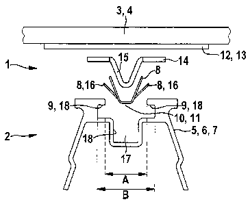
having an engagement section for a mounting tool.
-1-
CA 02725344 2010-12-15
[0004] German patent application DE 10 2006 011 836 B3 discloses a fastening
element
having a baseplate. Opposing first arms, which each have a first contact
section, project from the
baseplate at a first distance from the baseplate, and at least two opposing
second arms, which
have a second contact section, also project from the baseplate at a second
distance from the
baseplate. Here, the first arms have actuation sections that are each
configured as a surface with
an eyelet.
[0005] German patent application DE 10 2007 042 484 B3 discloses a device for
fastening
an add-on component to a support part, having a head part that has contact
sections projecting
laterally and that is intended for contact with the add-on component or with
the support part. An
elastic front wall arrangement has two barrier flaps that are oriented
approximately at a right
angle relative to the front wall. These barrier flaps have latching steps that
rest on the support
part when the device is in a catching position.
[0006] It is the objective of the present invention to put forward a device
and a system with
which add-on components can be fastened to a support part by means of the
device and by means
of the system employing a simple technical set-up and without having to use
tools. Furthermore,
the device and the system should be cost-effective to produce and should allow
simple and
reliable handling.
[0007] This objective is achieved with a device for fastening an add-on
component to a
support part, comprising at least one catching part that can be inserted into
an opening of the
support part and that can catch behind at least one edge of the support part
with at least one
movable holding element which, when it is inserted into the opening, can be
moved into an
engagement position owing to contact between the at least one catching part
and the support part,
so that it can be inserted into the opening, and which can be moved into a
catching position by
means of a return movement of the at least one holding element after it has
been inserted into the
opening, so that the at least one holding element can catch behind the at
least one edge of the
support part so as to create a positive connection between the at least one
holding element and
the support part, also comprising at least one means for affixing the add-on
component to the
-2-
CA 02725344 2010-12-15
device, whereby, in the catching position, the at least one holding element is
arranged completely
in a chamber surrounded by the support part. Therefore, the device
advantageously has a
compact and simple structure since the at least one holding element, as a
movable component of
the device, does not take up much installation space, and a reliable
connection between the
device and the support part is easily ensured.
[0008] In particular, the at least one catching part comprises at least two
holding elements,
and/or the at least one holding element is in the catching position,
especially exclusively on a
wide side surface and/or on a narrow side surface of the at least one holding
element, and/or two
holding elements are arranged opposite from each other.
[0009] In another embodiment, the device can be fastened to the support part
by means of a
snap-in and/or latching mechanism.
[0010] Advantageously, the at least one holding element is an integral part of
the at least one
catching part.
[0011] In a supplementary embodiment, the at least one movable holding element
is not pre-
tensioned in the pre-mounting position. The at least one movable holding
element is in the pre-
mounting position when the device is not mounted on the support part and the
at least one
holding element is not in the insertion position and/or in the catching
position.
[0012] Preferably, the at least one movable holding element is configured to
be essentially,
especially exclusively, plate-shaped or disk-shaped. In this manner, the at
least one holding
element can be produced easily and cost-effectively, allowing a reliable
connection between the
device and the support part to be made.
[0013] In another embodiment, the at least one means encompasses a carrier
plate for
purposes of affixing the device to the add-on component, preferably directly.
-3-
CA 02725344 2010-12-15
[0014] In another embodiment, the at least one means encompasses an adhesive,
latching,
riveted and/or screwed connection for purposes of affixing the add-on
component to the device,
especially to the carrier plate.
[0015] In a supplementary embodiment, the device encompasses at least one
engagement
part that can be inserted into the opening of the support part.
[0016] Preferably, the geometry of the at least one engagement part is adapted
to the
geometry of the opening of the support part in such a way that the at least
one engagement part
can be at least partially inserted into the opening.
[0017] In one variant, the at least one engagement part has a preferably wedge-
shaped
projection that can be inserted into the opening.
[0018] In one supplementary variant, the at least one engagement part, aside
from the
projection, is configured with an essentially disk-like or plate-like shape.
[0019] In a practical manner, the at least one engagement part is arranged
between the at
least one catching part and the carrier plate. The at least one catching part
is thus arranged on or
fastened to the carrier plate indirectly by means of the at least one
engagement part.
[0020] In another embodiment, the carrier plate and/or the at least one
engagement part
and/or the at least one catching part is configured in one piece or in
multiple pieces.
[0021] In particular, the at least one holding element can be pivoted around a
rotational axis
and/or a translatory movement can be executed by the at least one holding
element, thanks to a
bearing, and/or the at least one holding element can be moved back and forth,
since the at least
one holding element itself can be elastically deformed and/or the at least one
holding element
can be elastically deformed by means of at least one separate elastic element,
especially a spring.
-4-
CA 02725344 2010-12-15
[0022] In a supplementary embodiment, the device is made at least partially,
especially
completely, of plastic or metal, for instance, aluminum or steel.
[0023] The invention relates to a system according to the invention for
fastening an add-on
component to a support part, comprising a device for fastening the add-on
component to the
support part, comprising at least one catching part that can be inserted into
an opening of the
support part and that can catch behind at least one edge of the support part
with at least one
movable holding element which, when it is inserted into the opening, can be
moved into an
engagement position owing to contact between the at least one catching part
and the support part
so that it can be inserted into the opening, and which can be moved into a
catching position by
means of a return movement of the at least one holding element after it has
been inserted into the
opening, so that the at least one holding element can catch behind the at
least one edge of the
support part so as to create a positive connection between the at least one
holding element and
the support part, also comprising at least one means for affixing the add-on
component to the
device, and also comprising the support part, whereby the device is configured
as a device
described in this patent application.
[0024] In another embodiment, the support part is a support rail, and/or the
opening is
preferably a groove and/or the opening opens up into a chamber delimited by
the inside contour
of the support part, so that the at least one edge is formed by the inner
contour of the support part
so that it can catch behind the at least one holding element.
[0025] In a supplementary embodiment, the opening is a mounting opening for
fastening the
device to the support part.
[0026] In a supplementary variant, when the device is fastened to the support
part, two
opposing holding elements are oriented with respect to a plane that runs
through a central
longitudinal axis of the support rail in such a way that the plane runs
through the two holding
elements and the plane is divided by the central longitudinal axis of the rail
into a first partial
plane and a second partial plane, and a first holding element is intersected
by the first partial
-5-
CA 02725344 2010-12-15
plane while a second holding element is intersected by the second partial
plane. The central
longitudinal axis of the rail is oriented in the direction of the greatest
extension of the support rail
and it runs through the center point or through the center of gravity of the
support rail.
100271 In another variant, the at least two holding elements can be pivoted
around a
rotational axis essentially parallel - that is to say, with a deviation of
less than 10 , especially
less than 5 - to the longitudinal axis of the rail, or else the rotational
axis is oriented at an angle,
preferably an essentially right angle, relative to the longitudinal axis of
the rail, and/or, before the
holding elements are inserted into the opening, the distance between the ends
of two opposite
holding elements in the direction of the distance is greater than the clear
width of the opening in
the direction of the distance, so that, when the two opposite holding elements
are inserted, the
holding elements can be moved due to the contact with the support part,
especially in such a way
that the maximum distance is reduced.
[0028] In another embodiment, when the device is fastened to the support part,
the at least
one holding element is pre-tensioned on the support part in the catching
position, and/or the
fastening of the device to the support part is a permanent connection.
[00291 Embodiments of the invention will be described in greater detail below
with reference
to the accompanying drawings. The following is shown:
Figure 1: a cross section of a system for fastening an add-on component, in an
exploded view;
Figure 2: a perspective view of an engagement part with a catching part;
Figure 3: a perspective view of the catching part, in a first embodiment;
Figure 4: a perspective view of catching parts as a modular arrangement, in a
second
embodiment;
-6-
CA 02725344 2010-12-15
Figure 5: a perspective view of several catching parts, in a third embodiment;
Figure 6: a cross section of the system for fastening the add-on component, in
a pre-mounting
state;
Figure 7: a cross section of the system according to Figure 6, during
insertion of the device
into an opening of the support part;
Figure 8: a cross section of the system according to Figure 6, in a final
mounted state;
Figure 9: a cross section of a device, in a first embodiment;
Figure 10: a perspective view of the device, in a second embodiment;
Figure 11: a perspective view of the catching part, in a second embodiment;
Figure 12: a detailed view of the system, with the catching part according to
Figure 11, in the
final mounted state.
[0030] In the fields of structural engineering and construction, devices 1 are
employed for
fastening an add-on component 3 to a support part 5. The add-on component 3
is, for instance, a
photovoltaic module 4, a facade element or a line (not shown here), and the
support part 5 is a
support rail 6 or a mounting rail 7. Therefore, the device 1 can be used to
fasten the add-on
component 3 to the support part 5 indirectly.
[0031] The device 1 comprises a carrier plate 13 as the means 12 for affixing
the add-on
component 3 to the device 1, an engagement part 14 with a projection 15 and a
catching part 8
with a movable holding element 16 (Figures 1, 2, 6, 7 and 8). The carrier
plate 13, the
engagement part 14 and the catching part 8 are made of metal, for example,
steel or aluminum,
and they are especially joined together (not shown here), for instance, by
means of adhesion or
-7-
CA 02725344 2010-12-15
welding, or else by a positive connection, for example, with screw or rivets
(not shown here) for
purposes of creating a screwed or riveted connection. The add-on component 3
is fastened to the
carrier plate 13 analogously. The engagement part 14, aside from the
projection 15, is configured
so as to be essentially disk-shaped or plate-shaped (Figure 2). As a result,
the engagement part 14
can be easily joined to the disk-shaped or plate-shaped carrier plate 13.
[0032] The mounting rail 7 has an opening 10 as a mounting opening, which is
configured as
a groove 11. The groove 11 extends with its larger extension in the direction
of the longitudinal
axis 19 of the rail. In this context, the inner contour 18 of the mounting
rail? surrounds a
chamber 17 into which the opening 10 opens up. In an orientation perpendicular
to the plane of
projection of Figures 1, 6, 7 or 8, the clear width A of the opening 10 is
smaller than the clear
width B of the chamber 17 adjacent to the opening 10. Together with the device
1, the mounting
rail 7, which is likewise made of metal, for instance, aluminum or steel, or
else of plastic, forms
a system 2 for fastening the add-on component 3 to the support part 5.
[0033] The catching part 8 has a holding element 16 that can be pivoted around
a pivoting
axis 25 (Figures 1 to 10). Here, the catching part 8 can be configured as a
single piece having
two holding elements (16) (Figure 3), as a single piece having more than two
holding elements
16 (Figure 3), for example, four holding elements 16 (Figure 4), or else in
modular form having
several pieces, for instance, three catching parts 8 (Figure 5). In this
context, the rotational axis
25 of the holding element 16 either can be oriented parallel to the
longitudinal axis 19 of the rail
in accordance with the embodiment in Figure 9, or else the rotational axis 25
can be oriented at
an angle, e.g. a right angle. Figure 10 shows the engagement part 14 and the
catching part 8
configured as a single part. In the embodiment of the device 1 shown in Figure
9, two holding
elements 16 are oriented opposite from the central longitudinal axis 19 of the
rail. A plane 20
that passes through the longitudinal axis 19 of the rail and that intersects
the two holding
elements 16 is divided by the longitudinal axis 19 of the rail into a first
partial plane 21 and a
second partial plane 22. The first partial plane 21 intersects the first
holding element 23, while
the second partial plane 22 intersects the second holding element 24. The
essentially disk-shape
-8-
CA 02725344 2010-12-15
or plate-shaped holding elements 16 have two wide side surfaces 26 and three
narrow side
surfaces 27 (Figure 3).
[00341 Figures 6 to 8 show the mounting sequence, that is to say, the
fastening of the device
I to the mounting rail 7. Figure 6 depicts a pre-mounting state in which the
holding elements 16
are in a pre-mounting position and the add-on part 3 is firmly joined to the
device 1. In the pre-
mounting position, the holding elements 16 are not pre-tensioned. The holding
elements 16 are
movable owing to the elastic deformation of the holding elements 16 or of the
catching part 8.
The holding elements 16 are thus also spring elements. In the pre-mounting
state depicted in
Figure 6, the distance between the ends of the holding elements 16 in a
direction parallel to a
plane formed by the carrier plate 13 and parallel to the plane of projection
of Figure 6 (distance
direction) is greater than the clear width A of the opening 10 or mounting
opening 10. When the
device I is inserted and moved into the opening 10 and into the chamber 17,
the wedge-shaped
orientation of the two holding elements 16 causes them to pivot around the
rotational axis 25, so
that the right-hand holding element 16 shown in Figure 7 pivots in a
counterclockwise rotational
direction around the rotational axis 25, while the left-hand holding element
16 moves in a
clockwise rotational direction around the rotational axis 25. As a result, the
two holding elements
16 are moved from the pre-mounting position into the engagement position shown
in Figure 7. In
the engagement position as depicted in Figure 7, the above-mentioned distance
between the ends
of the holding elements 16 is smaller than in the pre-mounting position of the
holding elements
16. When the projection 15 of the device I is inserted into the chamber 17,
the contact between
the ends of the holding elements 16 or between the outermost narrow side
surfaces 27 and the
mounting rail 7 is ended, so that the holding elements 16 move or snap into
the catching position
according to Figure 8 due to the elastic deformability of the holding elements
16. Consequently,
the holding elements 16 recover from the engagement position depicted in
Figure 7 and go into
the catching position depicted in Figure 8.
[00351 In the catching position of the holding elements 16 according to Figure
8, the holding
elements 16 rest with the front edges of the upper wide side surfaces 26 on
the support rail 6,
-9-
CA 02725344 2010-12-15
especially on the inner contour 18 of the support part 5 or of the mounting
rail 7. As a result, a
positive connection is created between the device 1 and the support part 5.
[0036] When the device 1 is mounted on the support part 5, the device 1 can be
first placed
onto the support rail 6. The distance between the holding elements 16 at the
ends is greater than
the clear width A of the opening 10. In order to move the device 1 from the
pre-mounting state
according to Figure 6 into a position according to Figure 7 when the device 1
is being inserted
into the opening 10 of the support part 5, owing to the requisite elastic
deformation of the
holding elements 16, additional force has to be exerted downwards onto the
device 1 in order to
overcome the elastic forces of the holding elements 16. The weight of the
device 1 and of the
add-on component 2 [sic] is not sufficient for this purpose. The elastic
properties of the holding
elements 16 or of the catching part 8 have been designed appropriately for
this purpose. As a
result, before the projection 15 is pressed into the opening 10 in order to
reach the catching
position, the device 1 and the add-on component 3 can be moved on the mounting
rail 7 in a
direction perpendicular to the plane of projection of Figures 6 to 8. In this
manner, for example,
when photovoltaic modules 4 are to be mounted, they can be first oriented on
the mounting rail
7, in other words, perpendicular to the plane of projection of Figures 6 to 8,
and then, only once
the final mounting position of the photovoltaic modules 4 has been reached,
they can be finally
fastened to the mounting rail 7 by additionally pressing and applying a
downward force, as
depicted in Figures 6, 7 and 8 in that the device I is moved into the final
mounted state as shown
in Figure 8.
[0037] Figures 11 and 12 depict a second embodiment of the catching part 8.
The holding
elements 16 each have at least one wedge element for wedging with the support
rail 6.
Preferably, the holding elements 16 each have two essentially triangular
bevels 28 on the sides
and a center part 29 in between. The two bevels 28 and the center part 29 are
single pieces and
form a holding element 16 having a geometry that differs from that of the
holding element 16 of
the catching part 8 in the above-mentioned first embodiment. In the final
mounted position of the
holding elements 16 (Figure 12), the upper narrow side surface 26 - which is
formed by the two
bevels 28 and by the center part 29 - of the holding elements 16 rests on the
support rail 6. The
-10-
CA 02725344 2010-12-15
two holding elements 16 are thus clamped with a wedge effect on the inner
contour 18 of the
support rail. Therefore, the holding elements 16 are pre-tensioned in the
catching position owing
to their elastic deformability. Consequently, the device 1 is additionally
fastened to the support
part 5 non-positively as well. Due to the wedge-like arrangement of the
holding elements 16 in
the chamber 17, additional pre-tensioning between the device 1 and the support
part 5 occurs
when the support rail 6 is moved downwards, for instance, due to settling, so
that such
movements cause the device 1, and thus also the add-on component 3, to be
moved along.
[0038] On the whole, the device 1 according to the invention and the system 2
according to
the invention entail considerable advantages. Add-on components 3 are fastened
to support parts
in a structurally simple manner. This translates into cost savings during the
production of the
device 1 and of the system 2 and, owing to the absence of pre-tensioning of
the holding elements
16 in the pre-mounting state, no unintentional movement of the holding
elements 16 occurs.
Therefore, in the pre-mounting state, neither the device 1 nor the system 2
sustain any damage
when the device 1 is subjected to small forces while in the pre-mounting
state. Even settling or
movements of the support part 5 can be partially or completely absorbed by the
system 2 in that
the device 1 moves along with the movement of the support part 5.
-11-