Sélection de la langue

Search

Sommaire du brevet 2725531 

Énoncé de désistement de responsabilité concernant l'information provenant de tiers

Une partie des informations de ce site Web a été fournie par des sources externes. Le gouvernement du Canada n'assume aucune responsabilité concernant la précision, l'actualité ou la fiabilité des informations fournies par les sources externes. Les utilisateurs qui désirent employer cette information devraient consulter directement la source des informations. Le contenu fourni par les sources externes n'est pas assujetti aux exigences sur les langues officielles, la protection des renseignements personnels et l'accessibilité.

Disponibilité de l'Abrégé et des Revendications

L'apparition de différences dans le texte et l'image des Revendications et de l'Abrégé dépend du moment auquel le document est publié. Les textes des Revendications et de l'Abrégé sont affichés :

  • lorsque la demande peut être examinée par le public;
  • lorsque le brevet est émis (délivrance).
(12) Demande de brevet: (11) CA 2725531
(54) Titre français: PROCEDE ET SYSTEME DE COMMANDE D'UNE INSTALLATION EOLIENNE EN CAS DE DEFAILLANCES DU RESEAU
(54) Titre anglais: CONTROL METHOD AND SYSTEM FOR A WIND POWER INSTALLATION IN CASE OF GRID FAULTS
Statut: Réputée abandonnée et au-delà du délai pour le rétablissement - en attente de la réponse à l’avis de communication rejetée
Données bibliographiques
(51) Classification internationale des brevets (CIB):
  • H02P 09/00 (2006.01)
  • H02P 09/10 (2006.01)
(72) Inventeurs :
  • ACEDO SANCHEZ, JORGE (Espagne)
  • CARCAR MAYOR, AINHOA (Espagne)
  • ELORRIAGA LLANOS, JOSU (Espagne)
  • MAYOR LUSARRETA, JESUS (Espagne)
  • SIMON SEGURA, SUSANA (Espagne)
  • SOLE LOPEZ, DAVID (Espagne)
  • ZABALETA MAEZTU, MIKEL (Espagne)
  • LOPEZ TABERNA, JESUS (Espagne)
  • MARROYO PALOMO, LUIS (Espagne)
(73) Titulaires :
  • INGETEAM ENERGY, S.A.
(71) Demandeurs :
  • INGETEAM ENERGY, S.A. (Espagne)
(74) Agent: MARKS & CLERK
(74) Co-agent:
(45) Délivré:
(86) Date de dépôt PCT: 2009-05-22
(87) Mise à la disponibilité du public: 2009-11-26
Licence disponible: S.O.
Cédé au domaine public: S.O.
(25) Langue des documents déposés: Anglais

Traité de coopération en matière de brevets (PCT): Oui
(86) Numéro de la demande PCT: PCT/ES2009/070177
(87) Numéro de publication internationale PCT: ES2009070177
(85) Entrée nationale: 2010-11-23

(30) Données de priorité de la demande:
Numéro de la demande Pays / territoire Date
P200801525 (Espagne) 2008-05-23

Abrégés

Abrégé français

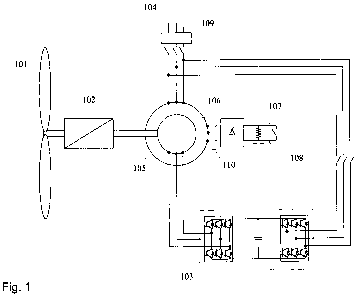
La presente invención se refiere a un método y sistema para el control de una instalación eólica conectada a una red eléctrica, cuando se produce una falta en dicha red. En las máquinas eléctricas que forman parte de la instalación eólica, generadores y transformadores, es posible modificar la impedancia de cierre del neutro introduciendo una pluralidad de elementos activos y pasivos. De esta forma se limitan las intensidades circulantes durante el fallo de red con lo que se reduce el pico de par en el tren mecánico de los aerogeneradores y permite a su vez garantizar el cumplimiento de los requisitos de conexión a red, ya que se mantiene en todo momento el control de las corrientes activas y reactivas.


Abrégé anglais


The present invention relates to a method and system
for controlling a wind power installation connected to an
electrical power grid, in case of a fault in said grid.
In the electrical machines that form part of the
wind power installation, generators and transformers, it is
possible to change the impedance of the neutral closure
introducing a plurality of active and passive elements.
This limits the currents during the grid fault, thereby
reducing the peak torque in the mechanical train of the
wind turbines and allows guaranteeing compliance with the
network connection requirements, as control of the active
and reactive currents is maintained at all times.

Revendications

Note : Les revendications sont présentées dans la langue officielle dans laquelle elles ont été soumises.


-6-
CLAIMS
1.- CONTROL SYSTEM FOR A WIND POWER INSTALLATION IN
CASE OF GRID FAULTS characterised in that it increases
temporarily the impedance between end terminals of
windings of an electrical machine and a neutral point of
the electrical machine of the wind power installation by
means of at least one rectifier element (106, 201, 401) and
one set of active (108, 203, 403) and passive (107, 202,
402) elements, being said one rectifier element and said
set of active and passive elements connected in series to
said end terminals of the windings, and being said windings
of the electrical machine selected from the group
consisting of generator rotor windings (204), generator
stator windings (110) and windings of at least one
transformer (404) of the wind power installation.
2.- CONTROL SYSTEM FOR A WIND POWER INSTALLATION IN
CASE OF GRID FAULTS according to claim 1, characterised in
that the temporarily increment of the impedance is carried
out by rectifying a current arriving from the windings of
the electrical machine to direct current, opening the
active element (108, 203, 403) and forcing the current
arriving from the windings of the electrical machine to
pass through the passive element (107, 202, 402) in
parallel to the active element (108, 203, 403).
3.- CONTROL SYSTEM FOR A WIND POWER INSTALLATION IN
CASE OF GRID FAULTS according to claim 1 or 2, applicable
in generators with a stator connected to the power grid,
characterised in that the terminals of the generator stator
windings (110) are connected to at least one rectifying
element (106); a DC output of the at least one rectifying
element (106) is connected to the one set of active (108)
and passive (107) elements.
4.- CONTROL SYSTEM FOR A WIND POWER INSTALLATION IN
CASE OF GRID FAULTS according to claim 1 or 2, applicable
in asynchronous type generators with a winding rotor, the

-7-
stator of which is connected to the power grid,
characterised in that the terminals of the generator rotor
windings (204) are connected to at least one rectifying
element (201); a DC output of the at least one rectifying
element (201) is connected to the one set of active (203)
and passive elements (202).
5.- CONTROL SYSTEM FOR A WIND POWER INSTALLATION IN
CASE OF GRID FAULTS according to claim 1, characterised in
that the terminals of a winding selected between a primary
winding and a secondary winding of one of the transformers
of the wind power installation are connected to at least
one rectifying element (401); a DC output of the at least
one rectifying element (401) is connected to the one set
of active (403) and passive (402) elements.
6.- CONTROL SYSTEM FOR A WIND POWER INSTALLATION IN
CASE OF GRID FAULTS according to any of the preceding
claims, characterised in that said the at least one
rectifying element (106, 201, 401) being a rectifier
bridge, the passive element (107, 202, 402) being an
impedance and the active element (108, 203, 403) being an
active switch, which is connected in parallel to the
impedance.
7.- CONTROL METHOD FOR A WIND POWER INSTALLATION IN
CASE OF GRID FAULTS that allows operating any of the
systems of the preceding claims, comprising the following
stages:
- detecting the grid perturbations;
- generating control signals for the active elements
that increase the impedance between end terminals of
windings of an electrical machine and a neutral
point of the electrical machine of the wind power
installation, being said windings selected from the
group consisting of generator rotor windings,
generator stator windings and windings of at least

-8-
one transformer of the wind power installation;
- detecting the end of the grid perturbations;
- generating control signals for the active elements
to return the impedance between end terminals of
windings of an electrical machine and a neutral
point of the electrical machine of the wind power
installation to the value prior to its variation.

Description

Note : Les descriptions sont présentées dans la langue officielle dans laquelle elles ont été soumises.


CA 02725531 2010-11-23
-1-
CONTROL METHOD AND SYSTEM FOR A WIND POWER INSTALLATION IN
CASE OF GRID FAULTS
OBJECT OF THE INVENTION
The present invention relates to a method and system
for controlling a wind power installation connected to an
electrical power grid, when a fault occurs in this grid.
BACKGROUND OF THE INVENTION
In recent years the number of wind power turbines and
wind farms connected to the electrical power grid has
increased considerably. For this reason, grid operators
have increased the performance requirements for wind
turbines, specifying certain requirements of behaviour in
case of faults (e.g. grid voltage dips) to prevent their
cut-off from the grid.
Among the various wind turbine types, those based
on double-fed topologies are most sensitive to grid
perturbations. In this type of topology, in case of a
voltage dip the rotor winding suffers high currents that
may damage the converter connected to the rotor.
There are currently several different solutions
that protect the converter from the high currents produced
in double-fed systems.
Some of these solutions (such as WO03/065567, WO
2004/091085 and WO 2005/015730), for example, introduce
impedances in parallel to the stator or the rotor of the
generator. However, these solutions require uncoupling the
generator from the grid or losing control of the generator
in the initial moments of the transition, thereby hindering
compliance with grid operator requirements.
Other solutions (WO03/058789) propose inserting
between the generator and the grid some impedances in
series with each of the stator phases. This requires

CA 02725531 2010-11-23
-2-
incorporating a high number of components in the system,
with the resulting increase in losses and risk of faults.
The invention disclosed presents an alternative
that allows, in case of grid fault, to keep the generator
connected to the grid and controlled at all times with a
small number of elements that provide improved performance
and reliability of the system. This invention intends to
limit the currents present during the grid fault, so that
the peak torque in the mechanical train is reduced and at
the same time guaranteeing compliance with grid connection
requirements, as the active and reactive currents are
controlled at all times.
DESCRIPTION OF THE INVENTION
The current in the asynchronous generator in the event
of a voltage dip of considerable magnitude may be reduced
by increasing the impedance of any of the paths followed by
the current or any of its reflections.
In electric machines involved in energy conversion,
for example a generator and a transformer, it is possible
to modify the impedance of the neutral closing by
introducing a plurality of active and passive elements.
Active elements refers to switches such as thyristors,
IGBTs, relays, contactors etc. Passive elements refers to
any combination of impedances (resistances, inductances and
capacitors).
The control system of the invention relates to a wind
power installation in case of grid faults that is
characterised by having at least one rectifier element and
one set of active and passive elements that are connected
to close a neutral. This neutral can be that of the
generator rotor, the generator stator or that of at least
one transformer of the wind power installation.
Therefore, the invention has an element that can vary
temporarily the impedance of the closure of the neutral of

CA 02725531 2010-11-23
-3-
one of the system elements using a rectifying element and a
set of passive and active elements. Specifically, it could
act on the connection of the generator rotor, the generator
stator or on one of the windings (primary or secondary) of
any of the transformers of the wind power installation,
such as the transformers of the wind turbines, the
substation or any other transformer present in the internal
grid of the wind power installation.
The control method of the invention relates to a wind
power installation and includes the following phases:
detecting the grid perturbations; generating control
signals for the active elements that modify the impedance
of the closure of the selected neutral, selecting this
neutral from among that of the generator rotor, the
generator stator and the neutral of at least one
transformer of the wind power station; detecting the end of
the grid perturbations and generating control signals for
the active elements to return to the impedance value of the
neutral prior to modification.
To aid a better understanding of this description and
as an integral part of it, a set of drawings are
accompanied where the object of the invention has been
represented for purposes of illustration and in a non-
limiting sense.
BRIEF DESCRIPTION OF THE FIGURES
Figure 1.- Shows a general schematic representation of
the operation according to a preferred embodiment in which
the closing of the neutral of the stator of a winding rotor
asynchronous generator is acted upon.
Figure 2.- Shows a general schematic representation of
the operation according to a preferred embodiment in which
the closing of the neutral of the rotor of a winding rotor
asynchronous generator is acted upon.
Figure 3.- Shows a general schematic representation of
the operation according to a preferred embodiment in which

CA 02725531 2010-11-23
-4-
the closing of the neutral of the transformer of a winding
rotor asynchronous generator is acted upon.
Figure 4.- Shows a detailed representation of the
transformer block (301) of the previous figure (figure 3).
DESCRIPTION OF ONE OR SEVERAL EXAMPLES OF EMBODIMENT OF THE
INVENTION
A description is now made of examples of the invention
with reference to the figures. First the system of the
invention will be described, followed by the method of
operation, which is common to all embodiments.
In the preferred embodiment an asynchronous generator
with a winding rotor is used. However, the invention is
applicable to wind turbines with any other type of
asynchronous generator.
In a preferred embodiment of the invention (figure 1)
the neutral closing of a winding-rotor asynchronous stator
generator (105) is acted on. This figure shows a generator
(105) with the start and end terminals of each stator
winding accessible. A rectifier bridge (106) is connected
to the end terminals of each of the aforementioned stator
windings (110). At the dc output of the rectifier bridge
(106) is connected an impedance (107) in parallel to an
active switch (108) (such as a thyristor, IGBT or the
like).
In another preferred embodiment (Figure 2) the
rectifier bridge (201) with the impedance (202) and the
active switch (203) can act on the closing of the neutral
of the windings (204) of the rotor of the generator (105).
In addition, in another preferred embodiment (Figure 3
- Figure 4) the rectifier bridge (401) with the impedance
(402) and the active switch (403) can be connected to any
of the windings (404) (primary or secondary) of any of the
transformers (301) of the wind power installation.
In normal operation, in each preferred embodiment the
impedance of the neutral closure is reduced by short-
AME!NDED
SHEET

CA 02725531 2010-11-23
-5-
circuiting the impedances (107, 202, 402) by activating the
active switch (108, 203, 403) in order to minimise losses.
The situation is then the same as if the corresponding
electric machine was star-connected.
If a voltage dip is detected the control will act by
opening the active switch (108, 203, 402), forcing the
current arriving from the generator (105) to pass, after it
is rectified to direct current, through the impedance (107,
202, 402) in parallel to the active switch (108, 203, 403).
This allows reducing the current and maintaining the
generator connected to the grid, while keeping the system
controlled at all times. In this case the system control
parameters may be varied to adjust to the new operation
conditions.
When the end of the grid perturbations is detected the
active switch (108, 203, 403) will be closed, short-
circuiting the impedances (107, 202, 402).
AMENDED
S H IEET

Dessin représentatif
Une figure unique qui représente un dessin illustrant l'invention.
États administratifs

2024-08-01 : Dans le cadre de la transition vers les Brevets de nouvelle génération (BNG), la base de données sur les brevets canadiens (BDBC) contient désormais un Historique d'événement plus détaillé, qui reproduit le Journal des événements de notre nouvelle solution interne.

Veuillez noter que les événements débutant par « Inactive : » se réfèrent à des événements qui ne sont plus utilisés dans notre nouvelle solution interne.

Pour une meilleure compréhension de l'état de la demande ou brevet qui figure sur cette page, la rubrique Mise en garde , et les descriptions de Brevet , Historique d'événement , Taxes périodiques et Historique des paiements devraient être consultées.

Historique d'événement

Description Date
Le délai pour l'annulation est expiré 2013-05-22
Demande non rétablie avant l'échéance 2013-05-22
Réputée abandonnée - omission de répondre à un avis sur les taxes pour le maintien en état 2012-05-22
Lettre envoyée 2011-05-06
Inactive : Correspondance - Transfert 2011-04-12
Inactive : Lettre officielle 2011-04-05
Inactive : Transfert individuel 2011-02-10
Inactive : Page couverture publiée 2011-02-08
Inactive : Notice - Entrée phase nat. - Pas de RE 2011-01-20
Inactive : CIB attribuée 2011-01-14
Inactive : CIB en 1re position 2011-01-14
Demande reçue - PCT 2011-01-14
Exigences pour l'entrée dans la phase nationale - jugée conforme 2010-11-23
Demande publiée (accessible au public) 2009-11-26

Historique d'abandonnement

Date d'abandonnement Raison Date de rétablissement
2012-05-22

Taxes périodiques

Le dernier paiement a été reçu le 2011-03-17

Avis : Si le paiement en totalité n'a pas été reçu au plus tard à la date indiquée, une taxe supplémentaire peut être imposée, soit une des taxes suivantes :

  • taxe de rétablissement ;
  • taxe pour paiement en souffrance ; ou
  • taxe additionnelle pour le renversement d'une péremption réputée.

Les taxes sur les brevets sont ajustées au 1er janvier de chaque année. Les montants ci-dessus sont les montants actuels s'ils sont reçus au plus tard le 31 décembre de l'année en cours.
Veuillez vous référer à la page web des taxes sur les brevets de l'OPIC pour voir tous les montants actuels des taxes.

Historique des taxes

Type de taxes Anniversaire Échéance Date payée
Taxe nationale de base - générale 2010-11-23
Enregistrement d'un document 2011-02-10
TM (demande, 2e anniv.) - générale 02 2011-05-24 2011-03-17
Titulaires au dossier

Les titulaires actuels et antérieures au dossier sont affichés en ordre alphabétique.

Titulaires actuels au dossier
INGETEAM ENERGY, S.A.
Titulaires antérieures au dossier
AINHOA CARCAR MAYOR
DAVID SOLE LOPEZ
JESUS LOPEZ TABERNA
JESUS MAYOR LUSARRETA
JORGE ACEDO SANCHEZ
JOSU ELORRIAGA LLANOS
LUIS MARROYO PALOMO
MIKEL ZABALETA MAEZTU
SUSANA SIMON SEGURA
Les propriétaires antérieurs qui ne figurent pas dans la liste des « Propriétaires au dossier » apparaîtront dans d'autres documents au dossier.
Documents

Pour visionner les fichiers sélectionnés, entrer le code reCAPTCHA :


Pour visualiser une image, cliquer sur un lien dans la colonne description du document. Pour télécharger l'image (les images), cliquer l'une ou plusieurs cases à cocher dans la première colonne et ensuite cliquer sur le bouton "Télécharger sélection en format PDF (archive Zip)" ou le bouton "Télécharger sélection (en un fichier PDF fusionné)".

Liste des documents de brevet publiés et non publiés sur la BDBC .

Si vous avez des difficultés à accéder au contenu, veuillez communiquer avec le Centre de services à la clientèle au 1-866-997-1936, ou envoyer un courriel au Centre de service à la clientèle de l'OPIC.


Description du
Document 
Date
(aaaa-mm-jj) 
Nombre de pages   Taille de l'image (Ko) 
Description 2010-11-22 5 195
Revendications 2010-11-22 3 100
Abrégé 2010-11-22 1 17
Dessins 2010-11-22 4 49
Dessin représentatif 2011-01-20 1 7
Rappel de taxe de maintien due 2011-01-24 1 112
Avis d'entree dans la phase nationale 2011-01-19 1 194
Courtoisie - Certificat d'enregistrement (document(s) connexe(s)) 2011-05-05 1 104
Courtoisie - Lettre d'abandon (taxe de maintien en état) 2012-07-16 1 174
PCT 2010-11-22 10 354
Correspondance 2011-04-04 1 14