Note : Les descriptions sont présentées dans la langue officielle dans laquelle elles ont été soumises.
CA 02726559 2013-02-26
Powder Actuated Tool and Connector
BACKGROUND
Field of the Invention
[0001] The invention relates to an electrical
connector tool and connector and, more particularly, to a
powder actuated electrical connector tool and connector.
Brief Description of Prior Developments
[0002] U.S. Patent Nos. 4,722,189, and 7,328,751,
which may be referred to in their entireties for further
details, disclose explosively-operated tools. These
tools generally provide an assembly to connect an
electrical wedge connector to conductors of electrical
power distribution systems. As maintenance
and
installation operations for the electrical power
distribution systems become increasingly difficult, the
added time required for these operations can increase
operating costs for the utility company.
[0003] Accordingly,
there is a need for an improved
electrical connector tool and electrical connector which
allows for facilitated installation while maintaining a
robust and reliable product configuration.
SUMMARY
[0004] The foregoing
and other problems are overcome,
and other advantages are realized, by the use of the
exemplary embodiments of this invention.
[0005] In accordance
with one aspect of the invention,
an electrical wedge connector wedge is disclosed. The
CA 02726559 2010-12-29
electrical wedge connector wedge includes a first end, a
second end, a first conductor groove, and an opening.
The second end is opposite the first end. The wedge
includes a generally tapered shape from the second end to
the first end. The first
conductor groove extends
between the first end and the second end. The opening
extends into the second end. The opening is adapted to
receive at least a portion of an explosive charge for
driving the wedge into an electrical wedge connector
shell.
[0006] In accordance with another aspect of the
invention, an electrical wedge connector installation
tool is disclosed. The electrical
wedge connector
installation tool includes a main section and a firing
ram. The firing ram extends from the main section in a
first direction. The tool is
adapted to impact an
electrical wedge connector wedge in the first direction.
The firing ram is adapted to receive gasses of an
explosive charge in a direction opposite the first
direction.
[0007] In accordance with another aspect of the
invention, an electrical wedge connector wedge is
disclosed. The electrical wedge connector wedge includes
a body and a firing pin. The body has a first end, a
second end opposite the first end, and a middle section
between the first end and the second end. The body
includes a generally tapered shape from the second end to
the first end. The body
includes a first conductor
groove extending along a side of the body between the
first end and the second end. The wedge is adapted to be
inserted into an electrical wedge connector shell by an
installation tool. The firing
pin is at the middle
2
CA 02726559 2010-12-29
section. The firing pin
is adapted to contact an
explosive charge of the installation tool.
[0008] In accordance with another aspect of the
invention, an electrical wedge connector installation
tool is disclosed. The electrical
wedge connector
installation tool includes a main section and a firing
ram. The firing ram includes a first end and a second
end. The first end is at the main section. The second
end is spaced from the main section. The second end is
adapted to be received by an electrical wedge connector
wedge. The second end
includes a cartridge receiving
area. The cartridge receiving area is adapted to receive
an explosive cartridge used in the tool.
[0009] In accordance with another aspect of the
invention, a method of using an electrical wedge
connector installation tool is disclosed. An end of a
firing ram is located proximate an opening of an
electrical wedge connector wedge. An explosive cartridge
is installed between the end of the firing ram and the
electrical wedge connector wedge. The ram is
moved
towards the wedge. The explosive
cartridge is struck
with a firing pin in response to the moving of the ram.
BRIEF DESCRIPTION OF THE DRAWINGS
[0010] The foregoing
aspects and other features of the
invention are explained in the following description,
taken in connection with the accompanying drawings,
wherein:
3
CA 02726559 2010-12-29
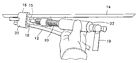
[0011] Fig. 1 is a
perspective view of a tool and
electrical connector incorporating features of the
invention;
[0012] Fig. 2 is a
perspective view of the tool shown
in Fig. 1;
[0013] Fig. 3 is a
section view of the electrical
connector shown in Fig. 1;
[0014] Fig. 4 is a
section view of an electrical
connector in accordance with an alternate embodiment used
with the tool shown in Fig. 1; and
[0015] Fig. 5 is a
section view of an electrical
connector in accordance with another alternate embodiment
used with the tool shown in Fig. 1.
DETAILED DESCRIPTION
[0016] Referring to Fig. 1, there is shown a
perspective view of a tool 10 incorporating features of
the invention. Although the invention will be described
with reference to the exemplary embodiments shown in the
drawings, it should be understood that the invention can
be embodied in many alternate forms of embodiments. In
addition, any suitable size, shape or type of elements or
materials could be used.
[0017] The tool 10 is
used for connecting a branch or
tap wire 12 to a main power line 14. The electrical
wedge connector 16 includes a wedge 18 and a C-shaped
sleeve 20. The tool 10 uses a charge (or cartridge/load)
15 to drive the wedge 18 into the sleeve (or shell) 20
sandwiching the wire 12 and line 14 against opposite ends
4
CA 02726559 2010-12-29
of the sleeve 20. The tool is fired by a user striking
the rear end 22 of the tool 10 with a hand-held hammer
19.
[0018] Referring also
to Fig. 2, there is shown an
enlarged perspective view of the tool 10. The tool 10
may be a hammer actuated connecting tool. The tool 10
includes a frame 24 and a tool body 26. The frame 24
comprises an anvil section 28. The tool body
26 is
adjustably connected to the frame 24. The tool body 26
is fitted through a support sleeve 30 at an end of the
anvil section 28 to position the ram 32 along the
longitudinal axis of the tool 10. The tool body
26
comprises the ram 32 which is adapted to contact the
charge 15 in order to initiate the advancement of the
wedge 16, to wedge the two cables 12, 14 into the shell
20 to drive the wedge 18 into its final position.
[0019] The tool body
26 includes a main section 34,
and a movable outer section 36. The main section 34 has
a threaded section 38 inserted into the support sleeve 30
for adjustment of the tool body 26 with respect to the
anvil section by means of a threaded connection 40. This
adjustable connection can be used for advancing and
retracting the tool body 26 and the ram 32 relative to
the opposite side of the anvil section for engagement
with the connector. The main
section 34 is threaded
along its forward surface at the threaded section 38.
The main section 34 includes a longitudinal axial bore
for slidably receiving the ram 32.
[0020] The main section 34 comprises a general
cylindrical shape. The movable
outer section 36 is
slidably fitted over the main section 34. The movable
CA 02726559 2010-12-29
outer section 36 may also comprise a general cylindrical
shape. A striker 42 may further be provided at the rear
end 22 of the movable section 36. The striker 42
is
adapted to be hit by the hand-held hammer 19 (see Fig.
1). According to one embodiment of the invention, when
the striker 42 is hit by the hammer 19, this causes the
movable outer section 36 to move in a direction towards
the frame 24, wherein an interior end portion of the
section 36 contacts an end 44 of the ram 32. According
to another embodiment of the invention, the striker 42
may be movably connected to the outer section 36 such
that when the striker 42 is hit by the hammer 19, this
causes the striker 42 to move in a direction towards the
frame 24, wherein an opposite end of the striker 42
contacts the end 44 of the ram 32. However, any suitable
configuration for advancing the ram may be provided.
[0021] Referring now
also to Fig. 3, the ram 32
comprises a firing pin portion 46 at the end 48 of the
ram 32. The firing pin portion 46 is suitably located to
be aligned with the cartridge 15. Additionally, a seal
50 is provided at the ram 32 proximate the end 48.
[0022] The electrical wedge connector wedge 18
includes a front end 52, a middle section 54, and a rear
end 56. The rear end 56 is opposite the front end 52.
The middle section 54 is between the front end 52 and the
rear end 56. The wedge 18 comprises a generally tapered
shape from the rear end 56 to the front end 52.
Additionally, the wedge 18 includes conductor grooves 58
on sides of the wedge 18 extending between the front end
52 and the rear end 56. The wedge 18 further includes an
opening 60 extending into the rear end 56. The opening
6
CA 02726559 2010-12-29
60 is adapted to receive the explosive charge for driving
the wedge into the electrical wedge connector shell.
[0023] The opening 60
includes a first portion 62 and
a second portion 64. The first portion 62 forms a ram
receiving channel adapted to receive the firing ram 32.
The second portion 64 forms a cartridge receiving seat
adapted to removably receive the explosive cartridge 15.
The receiving seat 64 may be suitably sized and shaped to
receive the cartridge 15 in a press fit or friction fit
for example.
[0024] When the
firing ram 32 is inserted in to the
ram receiving channel 62, the seal 50, which may be an 0-
ring seal for example, contacts the ram receiving channel
62 and forms a gas expansion area (or cavity) 66 between
the end 48 of the ram 32 and the end 68 of the channel 66
(as the 0-ring 50 forms a seal between the ram 32 and the
channel 62). In this embodiment, the gas expansion area
66 has a general cylindrical shape to direct expanding
gases from a fired cartridge against the end 48 of the
ram 32. However, it should be noted that in an alternate
embodiment the gas expansion area might not be provided.
[0025] To use the
tool 10 to connect the electrical
wedge connector 16 to the conductors 12, 14, the
connector sleeve 20, the wedge 18 and the two conductors
12, 14 (see Fig. 1) are located and positioned at the
anvil section 28. The tool body
26 is rotated by the
operator relative to the anvil section 28. This causes
the threads 38 of the main section 34 and the support
sleeve 30 to move the tool body 26 towards the anvil
section 28. The operator stops rotating the tool body 26
when the anvil section 28 and the ram 32 sandwich the
7
CA 02726559 2010-12-29
connector sleeve, conductors, and wedge therebetween such
that the front end 48 of the ram 32 is in the receiving
channel 62 and proximate the cartridge 15.
[0026] The operator
may then strike the striker 42 (or
the end 22 of the movable outer section 36) with a hand
held tool, such as the hand-held hammer 19. This causes
the movable outer section 36 to move forward and apply a
force to the end 44 of the movable firing ram 32. The
force applied to the ram 32 causes the firing pin portion
46 at the end 48 of the ram 32 to come into contact with
the cartridge 15. This causes the firing pin portion 46
to ignite a primer of the cartridge 15 to thereby fire
the cartridge 15. The gases from the cartridge 15 move
into the cavity 66 and push against the wedge 18 (at the
end 68 of the ram receiving channel 62) to thereby drive
the wedge 18 into the connector sleeve 20 with the cables
12, 14 therebetween in a very tight electrical and
mechanical connection. This, for
example, provides a
firing ram 32 adapted to impact the electrical wedge
connector wedge 18 in a first direction 70, and wherein
the firing ram is adapted to receive gasses of the
explosive charge in a second direction 72. According to
one embodiment, the cartridge may comprise a vented rim
to allow for the gasses to move from the cartridge 15 to
the cavity 66. However, any
suitable configuration may
be provided.
[0027] Once the
connection is completed, the tool body
26 is unscrewed from the anvil 28, thus backing the ram
off of the connector wedge. The tool 10 is then removed
from the completed connection. The spent
cartridge 15
may then be removed from the wedge.
8
CA 02726559 2010-12-29
[0028] Referring now
also to Fig. 4, an electrical
wedge connector 116 in accordance with an alternate
embodiment of the invention is shown. The electrical
wedge connector 116 is similar to the electrical wedge
connector 16 and similar features are similarly numbered.
Similar to the embodiment described above, the electrical
wedge connector 116 includes a wedge 118 and the sleeve
20. Also similar to the embodiment described above, the
tool 10 is configured to drive the wedge 118 into the
sleeve 20 to sandwich the wire 12 and line 14 against
opposite ends of the sleeve 20. It should be noted that
the sleeve 20 is not shown in Fig. 4 for the purposes of
clarity.
[0029] The wedge 118
comprises a similar configuration
as the wedge 18. For example, the wedge 118 includes a
front end 52, a middle section 54, and a rear end 56.
The wedge 118 also comprises a generally tapered shape
from the rear end 56 to the front end 52 and includes
conductor grooves 58 on sides of the wedge 118. The
wedge 118 further includes an opening 60 extending into
the rear end 56. The opening 60 is adapted to receive
the explosive charge 15 for driving the wedge 118 into
the electrical wedge connector shell 20.
[0030] However, one
difference between the wedge 118
and the wedge 18 is that the wedge 118 is configured to
receive a bushing at the opening. The opening 60
includes a first portion 62 and a second portion 64. The
first portion 62 forms a ram receiving channel adapted to
receive the firing ram 32. The second portion 164 forms
a bushing receiving area to receive the bushing 190. The
bushing 190 may be a vented bushing, wherein the bushing
190 comprises openings 192 vented to the cavity 66.
9
CA 02726559 2010-12-29
However, in alternate embodiments, any suitable type
bushing may be provided. The bushing
190 comprises a
cartridge receiving seat 194 adapted to removably receive
the explosive cartridge 15. The receiving seat 194 may
be suitably sized and shaped to receive the cartridge 15
in a press fit or friction fit for example.
[0031] In this embodiment, the gases from the
cartridge 15 move into the cavity 66 through the openings
192 in the bushing and push against the wedge 118 (at the
end 68 of the ram receiving channel 62) to thereby drive
the wedge 118 into the connector sleeve 20 with the
cables 12, 14 therebetween in a very tight electrical and
mechanical connection. This, for
example, provides a
firing ram 32 adapted to impact the electrical wedge
connector wedge 118 in the first direction 70, and
wherein the firing ram 32 is adapted to receive gasses of
the explosive charge 15 in a second direction 72.
Although this embodiment describes the vented bushing as
allowing for the gasses to move from the cartridge 15 to
the cavity 66, it should be noted that a cartridge with a
vented rim may also be used instead of, or in addition
to, the vented bushing. However,
these are merely
provided as non-limiting examples, and any suitable
configuration may be provided.
[0032] Referring now
also to Fig. 5, a tool 200 and
electrical wedge connector 216 in accordance with another
embodiment of the invention are shown. The tool 200 and
the electrical wedge connector 216 are similar to the
tool 10 and the electrical wedge connector 16, 116 and
similar features are similarly numbered. Similar to the
embodiments described above, the electrical wedge
connector 216 includes a wedge 218 and the sleeve 20.
CA 02726559 2010-12-29
Also similar to the embodiment described above, the tool
200 is configured to drive the wedge 218 into the sleeve
20 to sandwich the wire 12 and line 14 against opposite
ends of the sleeve 20. It should be
noted that the
sleeve 20 is not shown in Fig. 5 for the purposes of
clarity.
[0033] As mentioned
above, the tool 200 is similar to
the tool 10. For example the tool 200 comprises a hammer
actuated connecting tool including the frame 24 and the
tool body 26. It should be noted that the frame 24 and
portions of the tool body 24 are not shown in Fig. 6 for
the purposes of clarity.
[0034] One difference
between the tool 200 and the
tool 10 is that the tool 200 is configured to receive the
charge at an end of the ram. In this embodiment, the ram
32 comprises an opening 274 at the end 48 of the ram 32.
An end of the opening forms a cartridge receiving seat
276. The opening
274 is suitably sized and shaped to
receive the cartridge 15. Additionally, the cartridge
receiving area 276 is substantially aligned with an
opening of the electrical wedge connector wedge 218. The
opening 274 may further comprise a cavity portion 278
adapted to receive gasses of the explosive charge 15.
The opening 274 is adapted to receive the explosive
charge 15 for driving the wedge 218 into the electrical
wedge connector shell 20.
[0035] The wedge 218
comprises a similar configuration
as the wedge 18, 118. For example,
the wedge 218
includes a front end 52, a middle section 54, and a rear
end 56. The wedge 218 also comprises a generally tapered
shape from the rear end 56 to the front end 52 and
11
CA 02726559 2010-12-29
includes conductor grooves 58 on sides of the wedge 218.
The wedge 218 further includes an opening 60 extending
into the rear end 56.
[0036] The opening 60
includes a first portion 62 and
a second portion 64. The first portion 62 forms a ram
receiving channel adapted to receive the firing ram 32.
However, one difference between the wedge 218 and the
wedge 18, 118 is that the wedge 218 is configured to
receive an end 17 of the cartridge such that the second
portion 64 forms a cartridge receiving seat adapted to
receive the end 17 of the explosive cartridge 15. The
receiving seat 64 may be suitably sized and shaped to
receive the end 17 of the cartridge 15.
[0037] Another
difference between the wedge 218 and
the wedge 18, 118 is that the wedge 218 comprises a
firing pin 280 at the middle portion 54 of the wedge 218.
An end 282 of the firing pin 280 is at the second portion
64 of the opening 60. The firing pin
280 is suitably
located to be aligned with the cartridge 15.
[0038] To use the
tool 200 to connect the electrical
wedge connector 216 to the conductors 12, 14, the
connector sleeve 20, the wedge 218 and the two conductors
12, 14 are located and positioned at the anvil section as
described above.
[0039] When the
operator strikes the striker 42 (or
the end 22 of the movable outer section 36) with a hand
held tool, such as the hand-held hammer 19. This causes
the movable outer section 36 to move forward and apply a
force to the end 44 of the movable firing ram 32. The
force applied to the ram 32 causes the end 48 of the ram
32 to fully enter the receiving area 62, and with the
12
CA 02726559 2010-12-29
cartridge 15 at the cartridge receiving seat 276 of the
ram 32, the firing pin 280 of the wedge 218 comes into
contact with the cartridge 15. This causes
the firing
pin 280 to ignite a primer of the cartridge 15 to thereby
fire the cartridge 15. The gases from the cartridge 15
move into the cavity 278, which causes pressure between
the end 17 of the cartridge 15 and the wedge 218 to push
against the wedge 218 to thereby drive the wedge 218 into
the connector sleeve 20 with the cables 12, 14
therebetween in a very tight electrical and mechanical
connection. This, for example, provides a firing ram 32
adapted to impact the electrical wedge connector wedge
218 in the first direction 70, and wherein the cavity 278
of the firing ram 32 is adapted to receive gasses of the
explosive charge 15 in a second direction 72.
[0040] According to
another embodiment, the ram 32 may
comprise the seal 50 as shown in Fig. 2 and the cartridge
15 may comprise a vented rim to allow for the gasses to
move from the cartridge to the cavity 66 between the end
48 of the ram 32 and the end 68 of the channel 62 (formed
with the seal between the ram 32 and the ram receiving
channel 62). According to another embodiment, the end 48
of the ram 32 may comprise a vented bushing (such as in
Fig. 4) at the opening 274. This together with the seal
50 at proximate end 48 of the ram (as in Figs. 3 and 4)
to allow for the gasses to move from the cartridge 15 to
the cavity 66 between the end 48 of the ram 32 and the
end 68 of the channel 62 (formed with the seal between
the ram 32 and the ram receiving channel 62). In these
alternate embodiments, the cavity 66 would form a gas
expansion area to direct expanding gases from the fired
cartridge 15 against the end 68 of the wedge 218 to drive
13
CA 02726559 2010-12-29
the wedge 218 into the shell 20. However, any suitable
configuration may be provided.
[0041] Once the connection is completed, the ram 32 is
removed from the ram receiving section 62 and the spent
cartridge 15 may then be removed from the ram 32.
[0042] It should be noted that the cartridge 15 may be
any suitable cartridge such as a metallic shell cartridge
manufactured by Winchester Ammunition, for example. The
cartridge may further comprise a standard industrial
blank 0.27 caliber cartridge; where the powder level of
the cartridge corresponds to the size of the connector.
However, in alternate embodiments, the invention could be
adapted to incorporate use of any suitable size of
cartridge; standard or specifically designed.
[0043] According to another example of the invention,
a method of using the electrical wedge connector
installation tool is disclosed. The method includes the
following steps. Locating an
end of a firing ram
proximate an opening of an electrical wedge connector
wedge. Installing an explosive cartridge between the end
of the firing ram and the electrical wedge connector
wedge. Moving the ram towards the wedge. Striking the
explosive cartridge with a firing pin in response to the
moving of the ram. It should be noted that any of the
above steps may be performed alone or in combination with
one or more of the steps.
[0044] Below are provided further descriptions of
various non-limiting, exemplary embodiments. The below-
described exemplary embodiments are separately numbered
for clarity and identification. This numbering
should
not be construed as wholly separating the below
14
CA 02726559 2010-12-29
descriptions since various aspects of one or more
exemplary embodiments may be practiced in conjunction
with one or more other aspects or exemplary embodiments.
That is, the exemplary embodiments of the invention, such
as those described immediately below, may be implemented,
practiced or utilized in any combination (e.g., any
combination that is suitable, practicable and/or
feasible) and are not limited only to those combinations
described herein and/or included in the appended claims.
[0045] (1) In one exemplary embodiment, an electrical
wedge connector wedge comprising: a first end; a second
end opposite the first end, wherein the wedge comprises a
generally tapered shape from the second end to the first
end; a first conductor groove extending between the first
end and the second end; and an opening extending into the
second end, wherein the opening is adapted to receive at
least a portion of an explosive charge for driving the
wedge into an electrical wedge connector shell.
[0046] An electrical wedge connector wedge as above,
wherein the opening comprises a first portion and a
second portion, wherein the first portion is adapted to
receive a firing ram, and wherein the second portion is
adapted to receive the portion of the explosive charge.
[0047] An electrical wedge connector wedge as above,
further comprising a second conductor groove extending
between the first end and the second end.
[0048] An electrical wedge connector wedge as above,
wherein the wedge is adapted to be insertable into an
electrical wedge connector sleeve.
CA 02726559 2010-12-29
[0049] An electrical wedge connector wedge as above,
further comprising a second conductor groove extending
between the first end and the second end, and wherein the
opening comprises a first portion and a second portion,
wherein the first portion is adapted to receive a firing
ram, and wherein the second portion is adapted to receive
the portion of the explosive charge.
[0050] An electrical wedge connector wedge as above,
wherein the wedge is adapted to be insertable into an
electrical wedge connector sleeve.
[0051] An electrical wedge connector wedge as above,
further comprising a bushing, wherein the bushing is
adapted to be fitted between the second portion of the
opening and the explosive charge.
[0052] An electrical wedge connector comprising: an
electrical wedge connector sleeve; and an electrical
wedge connector wedge as above, wherein the wedge is
insertable into the sleeve, and wherein the connector is
adapted to receive a conductor between the wedge and the
sleeve.
[0053] (2) In another exemplary embodiment, an
electrical wedge connector installation tool comprising:
a main section; and a firing ram extending from the main
section in a first direction, wherein the tool is adapted
to impact an electrical wedge connector wedge in the
first direction, and wherein the firing ram is adapted to
receive gasses of an explosive charge in a direction
opposite the first direction.
[0054] An electrical
wedge connector installation tool
as above, further comprising a seal on the firing ram,
16
CA 02726559 2010-12-29
wherein the seal is adapted to contact the electrical
wedge connector wedge.
[0055] An electrical
wedge connector installation tool
as above, wherein the firing ram comprises a cavity
adapted to receive the gasses of the explosive charge.
[0056] An electrical
wedge connector installation tool
as above, wherein an end of the firing ram is adapted to
be received by on opening of the electrical wedge
connector wedge.
[0057] An electrical
wedge connector installation tool
as above, wherein the main section is connected to a
frame.
[0058] (3) In another exemplary embodiment, an
electrical wedge connector wedge comprising: a body
having a first end, a second end opposite the first end,
and a middle section between the first end and the second
end, wherein the body comprises a generally tapered shape
from the second end to the first end, wherein the body
comprises a first conductor groove extending along a side
of the body between the first end and the second end, and
wherein the wedge is adapted to be inserted into an
electrical wedge connector shell by an installation tool;
and a firing pin at the middle section, wherein the
firing pin is adapted to contact an explosive charge of
the installation tool.
[0059] An electrical
wedge connector wedge as above,
wherein the body comprises an opening at the second end.
[0060] An electrical
wedge connector wedge as above,
wherein the opening comprises a first portion and a
17
CA 02726559 2010-12-29
second portion, wherein the first portion is adapted to
receive a firing ram, and wherein the second portion is
adapted to receive a portion of the explosive charge.
[0061] An electrical wedge connector wedge as above,
wherein the firing pin is at the second portion of the
opening.
[0062] An electrical wedge connector wedge as above,
wherein the body comprises a second conductor groove
extending along another side of the body between the
first end and the second end.
[0063] An electrical wedge connector comprising: an
electrical wedge connector sleeve; and an electrical
wedge connector wedge as above, wherein the wedge is
insertable into the sleeve, and wherein the connector is
adapted to receive a conductor between the wedge and the
sleeve.
[0064] (4) In another exemplary embodiment, an
electrical wedge connector installation tool comprising:
a main section; and a firing ram comprising a first end
and a second end, wherein the first end is at the main
section, wherein the second end is spaced from the main
section, wherein the second end is adapted to be received
by an electrical wedge connector wedge, wherein the
second end comprises a cartridge receiving area, and
wherein the cartridge receiving area is adapted to
receive an explosive cartridge used in the tool.
[0065] An electrical wedge connector installation tool
as above, wherein the firing ram comprises a cavity
adapted to receive the gasses of the explosive charge.
18
CA 02726559 2010-12-29
[0066] An electrical wedge connector installation tool
as above, wherein the cartridge receiving area is adapted
to be aligned with a firing pin of the electrical wedge
connector wedge.
[0067] An electrical wedge connector installation tool
as above, wherein the firing ram is adapted to surround a
majority of the explosive cartridge at the receiving
area.
[0068] An electrical wedge connector installation tool
as above, further comprising a frame, wherein the main
section is movably connected to the frame.
[0069] (5) In another exemplary embodiment, a method
of using an electrical wedge connector installation tool
comprising: locating an end of a firing ram proximate an
opening of an electrical wedge connector wedge;
installing an explosive cartridge between the end of the
firing ram and the electrical wedge connector wedge;
moving the ram towards the wedge; and striking the
explosive cartridge with a firing pin in response to the
moving of the ram.
[0070] A method of using an electrical wedge connector
installation tool as above, wherein the installing of the
explosive cartridge further comprises installing the
explosive cartridge in the opening of the electrical
wedge connector wedge.
[007].] A method of using an electrical wedge connector
installation tool as above, wherein the installing of the
explosive cartridge further comprises installing the
explosive cartridge in an opening at the end of the
firing ram.
19
CA 02726559 2010-12-29
[0072] A method of
using an electrical wedge connector
installation tool as above, wherein the firing pin is at
the end of the firing ram.
[0073] A method of
using an electrical wedge connector
installation tool as above, wherein the firing pin is at
the opening of the electrical wedge connector wedge.
[0074] It should be
understood that the foregoing
description is only illustrative of the invention.
Various alternatives and modifications can be devised by
those skilled in the art without departing from the
invention. Accordingly,
the invention is intended to
embrace all such alternatives, modifications and
variances which fall within the scope of the appended
claims.