Note : Les descriptions sont présentées dans la langue officielle dans laquelle elles ont été soumises.
CA 02726858 2010-12-03
DEVICE FOR USE IN A METHOD FOR THE PRODUCTION OF A PROTECTIVE
LAYER AND METHOD FOR THE PRODUCTION OF A PROTECTIVE LAYER
DESCRIPTION
[001] The present invention relates to a device for use in a method for the
galvanic
production of a protective layer featuring hard material particles on a
component of a
turbomachine, particularly a blade tip armoring of a blade tip of a rotor
blade. The
invention also relates to a method for the galvanic production of a protective
layer
featuring hard material particles on a component of a turbomachine,
particularly a blade
tip armoring of a blade tip of a rotor blade.
[002] To increase the efficiency, performance and service life of
turbomachines,
particularly of gas turbines in engine building, the component surfaces are
increasingly
being provided with various coatings. In engine building, this results in
respectively
improved aerodynamics, higher possible combustion temperatures and higher
possible
mechanical stress of the individual components. Thus, for example the
efficiency of the
turbomachine is codetermined in particular by the rotor gap between the tips
of the rotor
blades and the wall of the rotor housing facing the rotor or the rotor blades.
In order to
keep this gap as small as possible, a so-called air seal is used, wherein the
air seal is
defined by so-called running-in coatings on the inner side of the housing and
correspondingly hard coatings on the blade tips. Applying a so-called blade
tip armoring
significantly reduces the wear on the blade tip during the so-called running-
in in the
running-in coating. The galvanic application of abrasive particles is known in
the case of
turbine blades. Corresponding methods are described in US-A-5665217, US-A-
5437724
and US-A-5074970. In this case, to coat the blade tips, hard material
particles are made
available in an immersion bath featuring an electrolyte, which are applied to
the
corresponding blade tip during galvanizing with the metallic matrix layer,
particularly
with a nickel layer. In the process, the hard material particles are embedded
in the
galvanically applied metallic matrix layer. However, the disadvantage of the
known
method and devices is that they are relatively involved, because, among other
things,
1
CA 02726858 2010-12-03
structurally complicated devices are used for the galvanizing process. In
addition, very
high quantities of hard material particles are used to achieve the desired
concentrations
on the blade tips. Hard material particles, such as, e.g., hard material
particles made of
(cubic) boron nitride, are very expensive, however, so that the use of the
known method
is very expensive as a whole. In order to reduce these costs, an attempt was
made in
accordance with DE 3525079 Al to arrange the hard material particles or
abrasive
particles on an electrically non-conductive porous band. The disadvantage,
however, is
that the abrasive particles are fastened to the band by means of an adhesive
layer and
after galvanizing and applying the abrasive particles to the corresponding
component
surface, this adhesive connection must be separated again. This results in a
relatively
complicated process flow.
[003] As a result, the object of the present invention is providing a generic
device for
use in a method for the galvanic production of a protective layer featuring
hard material
particles on a component of a turbomachine, particularly a blade tip armoring
of a blade
tip of a rotor blade, which guarantees a simplified and more cost-effective
process flow.
[004] The object of the present invention is also to make available a generic
method
for the galvanic production of a protective layer featuring hard material
particles on a
component of a turbomachine, particularly a blade tip armoring of a blade tip
of a rotor
blade, which guarantees a simplified and more cost-effective process flow.
[005] These objects are attained by a device according to the features of
Claim 1 as
well as a method according to the features of Claim 10.
[006] Advantageous embodiments of the invention are described in the
subordinate
claims.
[007] A device according to the invention for use in a method for the galvanic
production of a protective layer featuring hard material particles on a
component of a
turbomachine, particularly a blade tip armoring of a blade tip of a rotor
blade includes a
pouch-, bag- or sack-like receiving device for receiving the hard material
particles,
wherein the receiving device is made of a net-, screen- or non-woven-like
material that
2
CA 02726858 2010-12-03
is pervious to an electrochemical coating solution and has a mesh size smaller
than the
diameter of the hard material particles. In addition, the receiving device is
designed
such that it can be removably attached with an opening over and around a
region of the
component to be coated. Attaching the receiving device over or around the
region of the
component to be coated makes it possible to make a defined quantity of hard
material
particles available for the coating. An unnecessary use of hard material
particles cannot
take place because the receiving device collects the hard material particles
possibly not
used for the coating so that they may be used again for a subsequent coating
process.
In addition, attaching the receiving device over and around the region of the
component
to be coated can be accomplished simply and quickly so that the process flow
as a
whole is greatly simplified.
[008] In advantageous embodiments of the device according to the invention,
the
opening of the receiving device is surrounded by a flexible seal. In
particular, the seal is
laminated into the edge of the opening. Due to the embodiment of a flexible
seal on the
edge of the opening of the receiving device, it is possible for it to be
readily fastened
securely to the component to be coated, for example, a blade tip of a rotor.
The
formation of a seal also guarantees that the hard material particles are only
applied in
the regions of the component that are actually to be coated.
[009] In other advantageous embodiments of the device according to the
invention,
the receiving device is connected in the region of its opening to an
attachment base
plate in such a way that the opening corresponds with an opening in the
attachment
base plate and the attachment base plate can be removably fastened to a cover.
In this
case, the cover has at least one orifice for receiving the regions of the
component to be
coated, wherein the opening of the attachment base plate is positioned over
these
regions with the opening of the receiving device. Such an embodiment of the
device
guarantees a secure and defined receiving of the regions of the component to
be
coated in the cover and a corresponding positioning of the receiving device
containing
the hard material particles over and around the regions of the component to be
coated.
The use of this type of receiving device simplifies the process flow, because
the
receiving device containing the hard material particles may be positioned
readily and
3
CA 02726858 2010-12-03
securely. In addition, the opening of the attachment base plate may be
surrounded by at
least one seal. This also guarantees that the hard material particles are made
available
actually only in the regions of the component that are to be coated. In
addition, at least
one fixation pin for insertion into a corresponding fixation opening of the
cover may be
configured on the side of the attachment base plate opposite from the
receiving device.
This guarantees an exact, simple and secure positioning of the receiving
device on the
cover. In another embodiment of the device according to the invention, the
cover has at
least one fixation device for removably fastening the cover to the component.
This also
makes a secure positioning of the cover on the desired component surfaces
possible. In
addition, it is possible for a seal surrounding the opening with a positive
fit to be
configured between the attachment base plate and the orifice. This guarantees
that the
hard material particles are embedded with the aid of the galvanically applied
metallic
matrix layer only in the regions of the component actually to be coated. The
hard
material particles in this case may be made of (cubic) boron nitride, ceramic,
titanium
carbide, tungsten carbide, chromium carbide, aluminum oxide or zirconium oxide
or a
mixture thereof. The particle size is normally between 30 to 200 pm, however,
other
particles sizes may also be used. The cover may be configured to be rigid or
flexible.
[0010] An inventive method for the galvanic production of a protective layer
featuring
hard material particles on a component of a turbomachine, particularly a blade
tip
armoring of a blade tip of a rotor blade includes the following steps:
a) Attachment of an opening of a pouch-, bag- or sack-like receiving device of
a
device filled with hard material particles over and around a region of the
component to
be coated, wherein the receiving device is made of a net-, screen- or non-
woven-like
material that is pervious to an electrochemical coating solution and has a
mesh size
smaller than the diameter of the hard material particles;
b) Placement of at least the regions of the component to be coated into an
immersion bath with the electrochemical coating solution and application of a
voltage for
forming a metallic matrix layer at least on the region of the component to be
coated with
the embedding of the hard material particles; and
4
CA 02726858 2010-12-03
c) Galvanic formation of a filler layer between the embedded hard material
particles.
[0011] The method according to the invention guarantees a simplified and cost-
effective process flow. In particular, a sufficiently high concentration of
hard material
particles is made available for the coating without said particles being
distributed freely
and in an uncontrolled manner in the electrochemical coating solution. In
addition, the
attachment of the receiving device over and around the region of the component
to be
coated is simple to carry out in terms of the process. In the case of the
method
according to the invention, unneeded hard material particles remain in the
receiving
device. They may then be used readily for a subsequent coating step provided
that the
concentration of hard material particles is still sufficient. Because the
receiving device is
made of a material that is pervious to the electrochemical coating solution,
the galvanic
process, i.e., the formation of a metallic matrix layer, especially a layer
containing nickel,
on the region of the component to be coated with the embedding of hard
material
particles is not hindered. The galvanic formation of the filler layer between
the
embedded hard material particles in accordance with the process step c) may be
carried out for example after a removal of the receiving device.
[0012] In a further advantageous embodiment of the method according to the
invention,
in process step c), a rotation of the component is carried out, wherein the
axis of
rotation of the component runs horizontally. The rotational movement of the
component
guarantees a uniform distribution of the hard material particles on the
component
surface to be coated. Because of gravity, the hard material particles in an
upper position
of the rotating component are pressed against the component surface to be
coated. In
this case, the component is placed completely into the immersion bath with the
electrochemical coating solution. However, it is also possible for the
component to be
immersed only partially or in sections into the galvanic immersion bath.
Especially in the
case of integrally bladed rotor disks or rotor rings (BLISK or BLING), the
desired uniform
distribution of the hard material particles on the blade tips is produced
because of the
rotation of the BLISK or BLING with a horizontally aligned axis of rotation.
5
CA 02726858 2010-12-03
[0013] In another advantageous embodiment of the method according to the
invention,
in process step a), the receiving device with the opening is put over the
region of the
component to be coated with a positive fit, wherein the opening is surrounded
by a
flexible seal. The flexible seal in this case may be laminated into the edge
of the
opening. Putting the receiving device over the component region to be coated
with a
positive fit guarantees that only these regions, i.e., the desired component
regions, are
coated. In addition, the cited placement process may be carried out simply and
quickly.
[0014] In a further advantageous embodiment of the method according to the
invention,
the receiving device is connected in the region of its opening to an
attachment base
plate in such a way that the opening of the receiving device corresponds with
an
opening in the attachment base plate and the attachment base plate can be
removably
fastened to a cover. The cover in this case has at least one orifice for
receiving the
regions of the component to be coated, wherein, in process step a), the
opening of the
attachment base plate is positioned over these regions with the opening of the
receiving
device. This process step also guarantees that only predetermined regions of
the
component are coated with the protective layer featuring the hard material
particles. In
addition, the to-be-coated components or component regions may be positioned
with a
positive fit in the cover quickly and simply by means of the cited orifices.
[0015] In other advantageous embodiments of the method according to the
invention,
the cover is removably fastened to the component prior to the process step a).
In this
case, the cover is designed such that it can accommodate one or more to-be-
coated
component regions in corresponding orifices. In addition, the cover may be
configured
to be flexible or rigid.
[0016] In another advantageous embodiment of the method according to the
invention,
the electrochemical coating solution used in process step b) and/or the
process step c)
contains nickel. This may be a nickel sulfamate solution in particular.
However, it is also
possible for the anode projecting into the galvanic immersion bath to use a
solid nickel
anode. Other metallic coating materials are also conceivable and are based in
particular
on the metallic composition of the component to be coated. The hard material
particles
6
CA 02726858 2010-12-03
used are normally made of (cubic) boron nitride, ceramic, titanium carbide,
tungsten
carbide, chromium carbide, aluminum oxide or zirconium oxide or a mixture
thereof.
Typical grain sizes of the hard material particles used are between 30 pm and
200 pm.
Other grain sizes may also be used.
[0017] Ina further advantageous embodiment of the method according to the
invention,
the filler layer formed in process step c) fills in the space between the hard
material
particles, wherein the hard material particles are integrated geometrically
into the filler
layer in a range between 65-90%. This results advantageously in a secure
fixation of
the hard material particles in the metallic matrix, wherein it is also
guaranteed that a
sufficiently large region of the hard material particles still projects from
the matrix
surrounding it.
[0018] In other advantageous embodiments of the method according to the
invention,
prior to the process step a), a cleaning and/or a covering of the components
takes place
with a subsequent removal of the cover in the regions to be coated and/or
chemical
pretreatment at least of the regions of the component to be coated. These
measures
serve to connect the metallic matrix of the applied protective layer readily
to the metallic
component surface. The type of pretreatment depends upon the composition of
the
component to be coated. Thus, the pretreatment of titanium components may
include
the following steps, for example:
1. Etching of the component in an acidic solution containing nitric acid as
well as
fluoride;
2. Actively pickling the etched component in a solution containing at least
sodium
nitrate or tetrafluoroboric acid and
3. Activation of the actively pickled component in an acidic bath or an acid
bath
containing nickel. After this type of pretreatment, the layer containing the
hard material
particles may be applied directly.
[0019] A component according to the invention is produced according to a
method
described in the foregoing, wherein the component is particularly a blade tip
of a rotor
7
CA 02726858 2010-12-03
blade of a compressor of an aircraft engine, particularly a BLISK or BLING.
These
bladed disks or rings are made in particular of titanium alloys or nickel
alloys. However,
it is also possible for these components to be produced from metal matrix
composite
materials having a titanium basis. It is also possible for these components to
be made of
so-called intermetallic materials of the type TiAI or Ti3Al.
[0020] Additional advantages, features and details of the invention are
disclosed in the
following description of a graphically depicted exemplary embodiment, which
shows:
[0021] Figure 1 a schematic representation of a device according to the
invention;
and
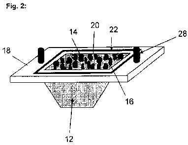
[0022] Figure 2 a schematic representation of a receiving device of the
inventive
device according to Figure 1.
[0023] Figure 1 shows a schematic representation of a device 10 for use in a
method
for the galvanic production of a protective layer featuring hard material
particles on a
component 38 of a turbomachine. The depicted exemplary embodiment shows a
blade
tip armoring of a blade tip 34 of a rotor blade 42. One can see that the
device 10 has a
bag-like receiving device 12 for receiving the hard material particles 14 (see
Figure 2),
wherein the receiving device 12 is made of a net-, screen- or non-woven-like
material
that is pervious to an electrochemical coating solution and has a mesh size
smaller than
the diameter of the hard material particles 14. In addition, the receiving
device 10 is
designed such that it can be removably attached with an opening 16 (see Figure
2) over
and around the region 40 of the component 38 to be coated. In the depicted
exemplary
embodiment, the receiving device 12 is connected in the region of its opening
16 to an
attachment base plate 18, wherein the opening 16 corresponds with an opening
20 in
the attachment base plate 18. The attachment base plate 18 in this case can be
removably fastened to a cover 24. The fastening is carried out in the depicted
exemplary embodiment through fixation pins 28, which are arranged on the side
of the
attachment base plate 18 opposite from the receiving device 12 and can be
inserted
into corresponding fixation openings 30 of the cover 24 (see Fig. 2).
8
CA 02726858 2010-12-03
[0024] One can also see that the cover 24 has several orifices 26 for
receiving the
blade tips 34 or the regions 40 of the component 38 to be coated. For the
coating
process, the opening 20 of the attachment base plate 18 is positioned with the
opening
16 of the receiving device 12 over the blade tips 34 or the regions 40 to be
coated. One
can see that the individual orifices 26 are surrounded respectively by a seal
36 with a
positive fit. The seal 36 in this case ends up between the attachment base
plate 18 and
the cover 24. The seal 36 is normally made of wax or rubber.
[0025] In addition, one can see that fixation devices 32 for removably
fastening the
cover 24 to the component 38 are configured on the cover 24. The to-be-coated
blade
tip 34 of the rotor blade 42 in the depicted exemplary embodiment is made of a
titanium
alloy.
[0026] Figure 2 show a schematic representation of the receiving device 12.
One can
see that the hard material particles 14 are concentrated in the receiving
device 12 that
is configured in a bag-like and non-woven-like manner. Normally, the hard
material
particles 14 are made of cubic boron nitride. In addition, one can see that
the opening
16 of the receiving device 12 is connected to the attachment base plate 18 in
such a
way that the opening 16 corresponds with the opening 20 in the attachment base
plate
18. In addition, it is clear that the opening 20 in the attachment base plate
is surrounded
by a seal 22. In addition, the two fixation pins 28 are arranged on the
attachment base
plate 18.
9