Sélection de la langue

Search

Sommaire du brevet 2728003 

Énoncé de désistement de responsabilité concernant l'information provenant de tiers

Une partie des informations de ce site Web a été fournie par des sources externes. Le gouvernement du Canada n'assume aucune responsabilité concernant la précision, l'actualité ou la fiabilité des informations fournies par les sources externes. Les utilisateurs qui désirent employer cette information devraient consulter directement la source des informations. Le contenu fourni par les sources externes n'est pas assujetti aux exigences sur les langues officielles, la protection des renseignements personnels et l'accessibilité.

Disponibilité de l'Abrégé et des Revendications

L'apparition de différences dans le texte et l'image des Revendications et de l'Abrégé dépend du moment auquel le document est publié. Les textes des Revendications et de l'Abrégé sont affichés :

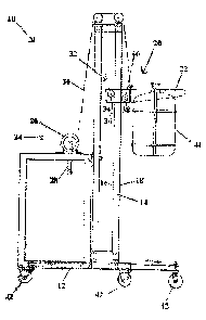
  • lorsque la demande peut être examinée par le public;
  • lorsque le brevet est émis (délivrance).
(12) Demande de brevet: (11) CA 2728003
(54) Titre français: APPAREIL DE LEVAGE A TREUIL ET CABLE
(54) Titre anglais: WINCH AND CABLE LIFTING APPARATUS
Statut: Réputée abandonnée et au-delà du délai pour le rétablissement - en attente de la réponse à l’avis de communication rejetée
Données bibliographiques
(51) Classification internationale des brevets (CIB):
  • B66F 09/08 (2006.01)
  • B66F 09/20 (2006.01)
(72) Inventeurs :
  • LENNOX, RICHARD B. (Canada)
  • LENNOX, KATHARINE H. (Canada)
(73) Titulaires :
  • RICHARD B. LENNOX
  • KATHARINE H. LENNOX
(71) Demandeurs :
  • RICHARD B. LENNOX (Canada)
  • KATHARINE H. LENNOX (Canada)
(74) Agent: DOUGLAS B. THOMPSONTHOMPSON, DOUGLAS B.
(74) Co-agent:
(45) Délivré:
(22) Date de dépôt: 2011-01-17
(41) Mise à la disponibilité du public: 2012-07-17
Licence disponible: S.O.
Cédé au domaine public: S.O.
(25) Langue des documents déposés: Anglais

Traité de coopération en matière de brevets (PCT): Non

(30) Données de priorité de la demande: S.O.

Abrégés

Abrégé anglais


A lifting apparatus has a vertical member supported in a vertical orientation.
A
travelling lift moves up and down the vertical member. A winch and cable
system provides a
lifting force to raise the travelling lift up the vertical member. An
engagement is provided
between the travelling lift and the vertical member which includes a single
upper bearing
roller mounted to the travelling lift for rotation about a substantially
horizontal first rotational
axis and engaging a first bearing surface of the vertical member. A single
lower bearing
roller is similarly mounted to the travelling lift for rotation about a
substantially horizontal
second rotational axis. The lower bearing roller is positioned lower on the
vertical member
than the upper bearing roller and engages a second bearing surface of the
vertical member,
opposed to the first bearing surface. The described engagement is simple,
inexpensive and is
self-aligning to eliminate binding.

Revendications

Note : Les revendications sont présentées dans la langue officielle dans laquelle elles ont été soumises.


What is Claimed is:
1. A lifting apparatus, comprising:
a support
at least one vertical member supported in a vertical orientation by the
support, the at
least one vertical member having a first bearing surface and a second bearing
surface
opposed to the first bearing surface;
a travelling lift that moves up and down the at least one vertical member, the
travelling lift having a load attachment portion extending in cantilever
fashion past the
second bearing surface;
a winch and cable system providing a lifting force to the load attachment
portion to
raise the travelling lift up the at least one vertical member, the travelling
lift descending by
force of gravity with a braking force being applied by the winch and cable
system;
an engagement between the travelling lift and the at least one vertical member
comprising:
a single upper bearing roller mounted to the travelling lift for rotation
about a
substantially horizontal first rotational axis, the upper bearing roller
engaging the first bearing
surface of the at least one vertical member;
a single lower bearing roller mounted to the travelling lift for rotation
about a
substantially horizontal second rotational axis, the lower bearing roller
being positioned
lower on the at least one vertical member than the upper bearing roller, the
lower bearing
roller engaging the second bearing surface of the at least one vertical
member.

Description

Note : Les descriptions sont présentées dans la langue officielle dans laquelle elles ont été soumises.

CA 02728003 2011-01-17
TITLE
[001] Winch and Cable Lifting Apparatus
FIELD
[002] There is described a winch and cable lifting apparatus which was
developed for
use in handling `'car boys" used by wine makers, but which has application to
lifting
apparatus generally.
BACKGROUND
[003] United States Patent 5,406,996 (Wagner et al) entitled "Bottled water
lifting
apparatus" discloses a winch and cable lifting apparatus for lifting water
bottles onto water
coolers. With all liflng apparatus that use a winch and cable to move a
travelling lifting arm
up and down a vertical member, there are concerns about binding. What is
required is a cost
effective configuration that will maintain alignment and be less prone to
binding.
SUMMARY
[004] There is provided a lifting apparatus, which includes a support with at
least one
vertical member supported in a vertical orientation by the support. The at
least one vertical
member has a first baring surface and a second bearing surface opposed to the
first bearing
surface. At least one travelling lift moves up and down the vertical member.
The travelling
lift has a load attachment portion extending in cantilever fashion past the
second bearing
surface. A winch and cable system provide a lifting force to the load
attachment portion to
raise the travelling lift up the at least one vertical member; the travelling
lift descending by
force of gravity with a braking force being applied by the winch and cable
system. An
engagement is provid d between the travelling lift and the at least one
vertical member which
includes a single ur dIrr bearing roller mounted to the travelling lift for
rotation about a
substantially ho izc:..ta _irst rotational axis. The upper bearing roller
engages the first bearing
surface of the at least cr i vertical member. A single lower bearing roller is
mounted to the
travelling lift for rotation about a substantially horizontal second
rotational axis. The lower
bearing roller is positioned lower on the at least one vertical member than
the upper bearing
roller, with the lower bearing roller engaging the second bearing surface of
the vertical
member.

CA 02728003 2011-01-17
2
[005] The lifting apparatus. as described above, is self aligning. Without a
load, the load
attachment portion is capable of being manually moved up and down like a
teeter totter.
When a load is actin; upon the load attachment portion, the travelling lift
tends to rotate
downwardly about the first rotational axis until such movement is stopped by
the lower
bearing roller engaging the second bearing surface and the upper bearing
roller engaging the
first bearing surface. When a lifting force is exerted upon the load
attachment portion by the
winch and cable system, the travelling lift is rotated upwardly about the
first rotational axis.
Binding does not occur as the positioning and spacing of the upper bearing
roller and the
lower bearing roller allows a limited degre: of freedom of movement; referred
to above as
the teeter totter move: oent. With such movement, there is also a lessening of
the engagement
between the lover baring roller and the second bearing surface as the
travelling lift ascends
the vertical member.
BRIEF DESCRIPTION OF THE DRAWINGS
[006] These and other features will become more apparent from the following
description in v.whicF. _eference is made to the appended drawings, the
drawings are for the
purpose of illustratis'' only and are not intended to be in any way limiting,
wherein:
[007] FIG. 1 is s side elevation view of a lifting apparatus.
[008] FIG. 2 is a top plan view, in section, of the lifting apparatus of FIG.
1.
[009] FIG. 3 is a detailed side elevation view, in section, of the rollers of
the lifting
apparatus of FIG. 1, ccs the travelling lift descends.
[0010] FIG. 4 is a detailed side elevation view, in section, of the rollers of
the lifting
apparatus of FIG. 1, ~,s die travelling lift ascends.
[0011] FIG. 5 is a, detailed side view of the rollers and side plates.
DETAILED DESCRIPTION
[0012] A lifting app ratus generally identified by reference numeral 10, will
now be
described with refer :-.ce to FIG. 1 through 5.
Structure and I; :lati ::ship of Parts:

CA 02728003 2011-01-17
[0013] Referring to FIG. 1, there is illustrated a lifting apparatus 10, which
includes a
support 12. A vertical member 14 is supported in a vertical orientation by
support 12.
Vertical member 14 has a first bearing surface 16 and a second bearing surface
18 that is
opposed to the first bearing surface 16. A travelling lift generally
referenced by numeral 20
is provided that moves up and down vertical member 14. Travelling lift 20 has
a load
attachment portion 22 that extends in cantilever fashion past second bearing
surface 18. It is
preferred that vertical member: 14 be square in cross-section. When a circular
cross-section is
used, there is a da_z 4er of lateral movement. When grooves are created to
limit lateral
movement. the:e is a anger of binding. It has been determined that a square or
rectangular
cross-section works best, with the first bearing surface 16 and the second
bearing surface 18
being flat.
[0014] Referring to FIG 1, a w--inch and cable system generally referenced by
numeral 24
is illustrated which iociudes a winch 26 with a handle 28, that is mounted to
support 12, and a
cable 30 that extcn 'can v inch 26 over vertical member to travelling lift 20.
Manual
rotational of hz:ndl~e ~h causes winch and cable system 24 to provide a
lifting force to load
attachment portion to raise travelling li,~;t 20 up vertical member 14.
Travelling lift 20
descends by force of gravity with a braking force being applied by winch and
cable system
24.
[0015] Referring L'o FIG 3 and 4, an engagement 32 between travelling lift 20
and vertical
member 14 inciad; l <: single upper bearing roller 34 mounted to travelling
lift 20 for rotation
about a substar._ia' , !i~ri:-om.al first rotatio.c.al axis 36. Upper bearing
roller 34 engages first
bearing 16 surface aer~ic.:rl rnernber 14. A single lower bearing roller 38 is
mounted to
travelling lift 20 for rotation E bout a substantially horizontal second
rotational axis 40.
Lower bearing roller 38 is positioned lower on vertical member 14 than upper
bearing roller
34. Lower bearing roller 38 engages second bearing surface 18 of vertical
member 14. It is
preferred that b >th up f c; bearing roller 34 and lower bearing roller 38
have side plates 39 of
high density p!at i . such as is sold under the Trademark name DELRIN. Side
plates 39
provide a bearing Su:.'-C- thr.t facilitate fr.: rf Cation of the rollers and
ensure that undue
friction is not .-use_ L a .gat 42. which prevnts the rollers from coming off
axles that
define their respecti , e rotational axes 36 argil 40. Referring to FIG 5,
upper bearing roller 34

CA 02728003 2011-01-17
4
is illustrated with side plates 39 with securing nut 42 and bolt 44 extending
there through.
The same arrangement is provided with lower bearing roller 38 illustrated in
FIG 4.
[0016] Referring to FIG 1 and FIG 2, support 12 can be outfitted with castors
42 as
shown to facilitate movement of lifting apparatus 10. Support 12 is
telescopically extendible
to provide additional stability as required.
Operation:
[0017] Referring to FIGS. 1 through 5. the use and operation of lifting
apparatus 10 will
now be described. Referring to FIG. 1, lifting apparatus 10 can be used to
lift loads, such as
a car boy 44. Lifting apparatus 10, as described above, is self-aligning.
Referring to FIG 4,
without a load 44, load attachment portion 22 is capable of rocking like a
teeter-totter.
Referring to FIG 3. w''.cn load 44 is acting upon load attachment portion 22,
travelling lift 20
tends to rotate downwardly about first rotational axis 36 until such movement
is stopped by
lower bearing roller 38 engaging second bearing surface 18 and upper bearing
roller 34
engaging first Lear; ig s_ rface 16. Referring *o FIG 4, when a lifting force
is exerted upon
load attachment por?_on 22 by winch and cable system 24, travelling lift 20 is
rotated
upwardly about firs: -.o:ational axis 36. Binding does not occur as the
positioning and
spacing of upper bca -na roller 34 and lower bearing roller 38 allows a
limited degree of
freedom of movc:rncnt. ref.--red to above as the teeter-totter movement. With
such
movement, there is also a lessening of the engagement between lower bearing
roller 38 and
second bearing surface 18 as travelling lift 20 ascends vertical member 14.
[0018] In this patent Jocumen . the word "_ cmprising" is used in its non-
limiting sense to
mean that items folk . ring the word are includedd, but items not specifically
mentioned are not
excluded. A referee- ce to s. element by the indefinite article "a" does not
exclude the
possibility that more than or,c of the element is present, unless the context
clearly requires
that there be one anJ only one ofthe elemeM.s.

CA 02728003 2011-01-17
[0019] The following claims are to be understood to include what is
specifically
illustrated and described above, what is conceptually equivalent, and what can
be obviously
substituted. Those skilled in the art will appreciate that various adaptations
and modifications
of the described embodiments can be configured without departing from the
scope of the
claims. The illustrated embodiments have been set forth only as examples and
should not be
taken as limiting the invention. It is to be understood that, within the scope
of the following
claims, the invention may be practiced other than as specifically illustrated
and described.

Dessin représentatif
Une figure unique qui représente un dessin illustrant l'invention.
États administratifs

2024-08-01 : Dans le cadre de la transition vers les Brevets de nouvelle génération (BNG), la base de données sur les brevets canadiens (BDBC) contient désormais un Historique d'événement plus détaillé, qui reproduit le Journal des événements de notre nouvelle solution interne.

Veuillez noter que les événements débutant par « Inactive : » se réfèrent à des événements qui ne sont plus utilisés dans notre nouvelle solution interne.

Pour une meilleure compréhension de l'état de la demande ou brevet qui figure sur cette page, la rubrique Mise en garde , et les descriptions de Brevet , Historique d'événement , Taxes périodiques et Historique des paiements devraient être consultées.

Historique d'événement

Description Date
Demande non rétablie avant l'échéance 2017-01-18
Le délai pour l'annulation est expiré 2017-01-18
Inactive : Abandon.-RE+surtaxe impayées-Corr envoyée 2016-01-18
Réputée abandonnée - omission de répondre à un avis sur les taxes pour le maintien en état 2016-01-18
Requête visant le maintien en état reçue 2012-11-27
Demande publiée (accessible au public) 2012-07-17
Inactive : Page couverture publiée 2012-07-16
Inactive : CIB attribuée 2011-02-23
Inactive : CIB en 1re position 2011-02-23
Inactive : CIB attribuée 2011-02-23
Inactive : Certificat de dépôt - Sans RE (Anglais) 2011-02-03
Inactive : Certificat de dépôt - Sans RE (Anglais) 2011-02-02
Demande reçue - nationale ordinaire 2011-02-02
Déclaration du statut de petite entité jugée conforme 2011-01-17

Historique d'abandonnement

Date d'abandonnement Raison Date de rétablissement
2016-01-18

Taxes périodiques

Le dernier paiement a été reçu le 2015-01-15

Avis : Si le paiement en totalité n'a pas été reçu au plus tard à la date indiquée, une taxe supplémentaire peut être imposée, soit une des taxes suivantes :

  • taxe de rétablissement ;
  • taxe pour paiement en souffrance ; ou
  • taxe additionnelle pour le renversement d'une péremption réputée.

Les taxes sur les brevets sont ajustées au 1er janvier de chaque année. Les montants ci-dessus sont les montants actuels s'ils sont reçus au plus tard le 31 décembre de l'année en cours.
Veuillez vous référer à la page web des taxes sur les brevets de l'OPIC pour voir tous les montants actuels des taxes.

Historique des taxes

Type de taxes Anniversaire Échéance Date payée
Taxe pour le dépôt - petite 2011-01-17
TM (demande, 2e anniv.) - petite 02 2013-01-17 2012-11-27
TM (demande, 3e anniv.) - petite 03 2014-01-17 2014-01-13
TM (demande, 4e anniv.) - petite 04 2015-01-19 2015-01-15
Titulaires au dossier

Les titulaires actuels et antérieures au dossier sont affichés en ordre alphabétique.

Titulaires actuels au dossier
RICHARD B. LENNOX
KATHARINE H. LENNOX
Titulaires antérieures au dossier
S.O.
Les propriétaires antérieurs qui ne figurent pas dans la liste des « Propriétaires au dossier » apparaîtront dans d'autres documents au dossier.
Documents

Pour visionner les fichiers sélectionnés, entrer le code reCAPTCHA :


Pour visualiser une image, cliquer sur un lien dans la colonne description du document (Temporairement non-disponible). Pour télécharger l'image (les images), cliquer l'une ou plusieurs cases à cocher dans la première colonne et ensuite cliquer sur le bouton "Télécharger sélection en format PDF (archive Zip)" ou le bouton "Télécharger sélection (en un fichier PDF fusionné)".

Liste des documents de brevet publiés et non publiés sur la BDBC .

Si vous avez des difficultés à accéder au contenu, veuillez communiquer avec le Centre de services à la clientèle au 1-866-997-1936, ou envoyer un courriel au Centre de service à la clientèle de l'OPIC.

({010=Tous les documents, 020=Au moment du dépôt, 030=Au moment de la mise à la disponibilité du public, 040=À la délivrance, 050=Examen, 060=Correspondance reçue, 070=Divers, 080=Correspondance envoyée, 090=Paiement})


Description du
Document 
Date
(aaaa-mm-jj) 
Nombre de pages   Taille de l'image (Ko) 
Dessins 2011-01-16 5 53
Abrégé 2011-01-16 1 22
Revendications 2011-01-16 1 31
Description 2011-01-16 5 205
Dessin représentatif 2011-10-26 1 10
Certificat de dépôt (anglais) 2011-02-02 1 157
Rappel de taxe de maintien due 2012-09-17 1 113
Rappel - requête d'examen 2015-09-20 1 117
Courtoisie - Lettre d'abandon (requête d'examen) 2016-02-28 1 165
Courtoisie - Lettre d'abandon (taxe de maintien en état) 2016-02-28 1 173
Correspondance 2011-01-17 3 64
Taxes 2012-11-26 1 34
Taxes 2014-01-12 1 23
Taxes 2015-01-14 1 24