Note : Les descriptions sont présentées dans la langue officielle dans laquelle elles ont été soumises.
P0008634.01 CA 02729454 2010-12-23
WO 2010/002527
PCT/US2009/045486
1
CHUCK FOR RECIPROCATING SURGICAL INSTRUMENT
FIELD OF THE INVENTION
The present invention relates generally to reciprocating surgical instruments
used
for cutting and modifying bone or other tough tissues. In particular, the
present invention
relates to a chuck or collet for use with said instruments, and especially for
securing
various blades and other tools to said instruments.
BACKGROUND
Doctors and other medical professionals often use powered surgical instruments
for dissecting bones, tissues and other purposes. Reciprocating saw-type
cutting
instruments may be used for surgical operations to cut through bone,
cartilage, or other
strong tissue. Depending on the manufacture or purpose, saw blades, bone burs,
rasps,
chisels, and other tools are often designed with varying tool profiles, such
as flat or round
shank profiles. It would be an improvement to have a reciprocating motion
surgical
instrument with a chuck that can readily accept blades, and other tools,
having flat, round,
or other shank profiles.
SUMMARY
The present invention provides improved methods and devices for securing a
surgical tool, such as a cutting blade within a reciprocating surgical
instrument, such as a
reciprocating saw. Cutting blades and other surgical tools are described that
are provided
with flat, round, or other shank profiles.
According to one exemplary embodiment, a chuck is disclosed for securing a
surgical tool having a shank with a securing aperture within a reciprocating
motion
P0008634.01 CA 02729454 2010-12-23
WO 2010/002527
PCT/US2009/045486
2
surgical instrument. The chuck comprises a shaft and a securing member. The
shaft
defines an axis and has a receptacle for receiving the shank of the tool. The
securing
member is carried by the shaft and is selectively moveable between a first
position
wherein the member is substantially withdrawn from the receptacle to permit
the insertion
and removal of the surgical tool, and a second position wherein the member is
substantially located within the receptacle and through the securing aperture
to secure the
surgical tool within the receptacle.
In another aspect, a securing chuck is disclosed for securing a surgical tool
to a
reciprocating surgical instrument that comprises a shaft and a securing
member. The shaft
defines an axis and has a cylindrical bore extending along the axis. The bore
is shaped to
receive a substantially rounded tool shank. A pair of transverse slots extends
into the shaft
along a plane passing through the axis for receiving a substantially flattened
tool shank.
The transverse slots intersect with the cylindrical bore. The securing member
is carried by
the shaft and is radially movable relative to the bore both inwardly and
outwardly to
secure the surgical tool in the chuck.
In some embodiments, a reciprocating surgical instrument comprises a motor, a
transmission, a surgical tool chuck, and a surgical tool. The motor has a
rotatable spindle
and a transmission is mounted to the spindle for converting rotating movement
of the
spindle to reciprocating movement. The surgical tool chuck is coupled to the
transmission
and comprises a receiving shaft, a locking member, and a camming sleeve. The
receiving
shaft defines an longitudinal axis and has a tool receptacle and a radially
extending
proximal opening. The locking member is slidingly coupled to the receiving
shaft and has
a protrusion extending therefrom. The camming sleeve is rotatingly retained on
the shaft
and has an internally cammed surface. The surgical tool has a distal end and a
proximal
end, the proximal end configured to be received into the tool receptacle. The
surgical tool
has an aperture disposed to correspond with the radially extending proximal
opening of the
receiving shaft when the surgical tool is disposed in the attachment
receptacle. The
locking member is selectively moveable between a first position and a second
position. In
the first position the protrusion is withdrawn from the proximal opening of
the receiving
shaft to allow insertion and removal of the surgical tool. In the second
position the
CA 02729454 2015-12-17
55054-32
3
protrusion is substantially received within the proximal opening of the
receiving shaft and the
aperture in the surgical tool to secure the surgical tool within the chuck.
The cammed surface
is configured to urge the protrusion into the second positon.
It should be understood that the present summary and the following detailed
description, while discussing some exemplary embodiments of the invention, are
intended for
purposes of illustration only and are not intended to limit the scope of the
invention beyond
that described in the claims.
In one aspect of the invention, there is provided a chuck for securing a
surgical
tool having a shank with a securing aperture within a reciprocating motion
surgical
instrument, comprising: a shaft defining an axis and having a receptacle for
receiving the
shank of the tool; and a securing member carried by the shaft that is
selectively moveable
between a first position wherein the member is substantially withdrawn from
the receptacle to
permit the insertion and removal of the surgical tool, and a second position
wherein the
member is substantially located within the receptacle and through the securing
aperture to
secure the surgical tool within the receptacle; wherein the receptacle
comprises both a
cylindrical bore in the shaft to receive a surgical tool having a
substantially cylindrical shank
and a transverse slot extending into sidewalls of the shaft to receive a
surgical tool having a
substantially flattened shank.
In another aspect of the invention, there is provided a chuck for securing a
surgical tool to a reciprocating surgical instrument, the chuck comprising: a
shaft defining an
axis and having a cylindrical bore extending along the axis, the bore shaped
to receive a
substantially rounded tool shank, the shaft also having a pair of transverse
slots extending into
the shaft along a plane passing through the axis for receiving a substantially
flattened tool
shank, the transverse slots intersecting with the cylindrical bore; and a
securing member
carried by the shaft and being radially movable relative to the bore both
inwardly and
outwardly to secure a surgical tool in the chuck.
CA 02729454 2016-11-29
* 55054-32
3a
In still another aspect of the invention, there is provided a system for
treating a
tissue structure during a surgical procedure, comprising: a reciprocating
surgical instrument,
comprising: a motor having a rotatable spindle; a transmission mounted to the
spindle for
converting rotating movement of the spindle to reciprocating movement; a
surgical tool chuck
coupled to the transmission, the chuck comprising: a receiving shaft defining
a longitudinal
axis and having a tool receptacle and a radially extending proximal opening; a
locking
member slidingly coupled to the receiving shaft, the locking member having a
protrusion
extending therefrom; and a camming sleeve rotatingly retained on the shaft,
the camming
sleeve having an internally cammed surface; and a surgical tool having a
distal end and a
proximal end, the proximal end configured to be received into the tool
receptacle, the surgical
tool having an aperture disposed to correspond with the radially extending
proximal opening
of the receiving shaft when the surgical tool is disposed in the tool
receptacle, wherein the
locking member is selectively moveable between a first position and a second
position, the
first position wherein the protrusion is withdrawn from the proximal opening
of the receiving
shaft to allow insertion and removal of the surgical tool, the second position
wherein the
protrusion is substantially received within the proximal opening of the
receiving shaft and the
aperture in the surgical tool to secure the surgical tool within the chuck,
the cammed surface
configured to urge the protrusion into the second position; wherein the tool
receptacle
comprises a cylindrical bore in the receiving shaft to receive a surgical tool
with a
substantially cylindrical shank and a transverse slot extending through
opposing sidewalls of
the receiving shaft to receive a surgical tool with a substantially flattened
shank.
In still another aspect of the invention, there is provided a chuck for
securing a
surgical tool having a shank with a securing recess to a surgical instrument,
comprising: a
shaft extending along an axis and having a receptacle for receiving the shank
of the tool; a
securing member radially movable relative to the receptacle from a first
position to a second
position; a camming sleeve positioned about the shaft and having a cam surface
that moves
the securing member between the first position and the second position; and a
retaining sleeve
configured to rotatably retain the camming sleeve relative to the shaft.
CA 02729454 2016-11-29
55054-32
3b
In still another aspect of the invention, there is provided a chuck for
securing a
surgical tool having a shank with a securing recess to a surgical instrument,
comprising: a
shaft extending along an axis and defining a receptacle for receiving the
shank of the tool; a
securing member movable into and out of the receptacle to secure the surgical
tool in the
receptacle; a camming sleeve positioned about the shaft and having a cam
surface configured
to move the securing member into and out of the receptacle; and at least one
ball member
biased outwardly from the shaft and configured to engage the camming sleeve to
retain the
camming sleeve relative to the shaft.
In still another aspect of the invention, there is provided a chuck for
securing a
surgical tool having a shank with a securing recess to a surgical instrument,
comprising: a
shaft extending along an axis and defining a receptacle for receiving the
shank of the tool; a
securing member radially movable relative to the receptacle from a first
position to a second
position and including a key portion that is complementary to the securing
recess of the
surgical tool; a retaining sleeve positioned about the shaft and defining a
slot for the securing
member; and a camming sleeve positioned about the retaining sleeve and
including a cam
surface configured to move the securing member between the first position and
the second
position to enable the tool to be secured or removed from the shaft in a key-
less manner.
In still another aspect of the invention, there is provided a chuck for
securing a
surgical tool having a shank with a securing recess to a surgical instrument,
comprising: a
shaft extending along an axis and defining a receptacle for receiving the
shank of the tool; a
securing member movable relative to the receptacle from a first position to a
second position;
and a camming sleeve positioned about the shaft and having a cam surface that
moves the
securing member between the first position and the second position, wherein
the camming
sleeve is rotatable relative to the shaft to enable the tool to be secured or
removed from the
shaft in a key-less manner.
CA 02729454 2016-11-29
55054-32
3c
BRIEF DESCRIPTION OF THE DRAWINGS
The present disclosure will become more fully understood from the detailed
description and the accompanying drawings, wherein:
Fig. lA is a cutaway, cross-sectional view of an exemplary reciprocating
motion surgical instrument constructed in accordance with the present
invention.
Fig. 1B is another cutaway, cross-sectional view of the exemplary
reciprocating motion surgical instrument of Fig. 1A.
Fig. 2 is an enlarged cutaway, cross-sectional view of an exemplary chuck for
use with the surgical instrument of Figs. 1A and 1B.
Fig. 3 is an exploded view of the chuck depicted in Fig. 2.
Fig. 4 is another enlarged cutaway, cross-sectional view of the exemplary
chuck in Fig. 2.
Fig. 5 is an end view of a portion of the chuck of Fig. 2.
Fig. 6A is a top view of an exemplary blade for use with the chuck of Fig. 2.
1 5 Fig. 6B is a top view of another exemplary blade for use with the
chuck of
Fig. 2.
Fig. 7A is a cutaway, cross-sectional view of the blade of Fig. 6A installed
in
the chuck of Fig. 2.
Fig.7B is another cutaway, cross-sectional view of the blade of Fig. 6A
installed in the chuck of Fig. 2.
Fig. 8 depicts an exemplary cutting blade having a rounded shank installed in
the chuck of Fig. 2.
P0008634.01 CA 02729454 2010-12-23
WO 2010/002527
PCT/US2009/045486
4
Fig. 9A depicts an exemplary rasp tool having a rounded shank installed in the
chuck of Fig. 2.
Fig. 9B depicts an exemplary rasp tool having an angled shank.
DETAILED DESCRIPTION
For the purposes of promoting an understanding of the principles of the
invention,
references will now be made to the embodiments, or examples, illustrated in
the drawings
and specific languages will be used to describe the same. It will nevertheless
be
understood that no limitation of the scope of the invention is thereby
intended. Any
alterations and further modifications in the described embodiments, and any
further
applications of the principles of the invention as described herein are
contemplated as
would normally occur to one skilled in the art to which the invention relates.
Further, it
will be understood that the present disclosure is not limited to any
particular surgical
application but has utility for various applications in which it is desired,
including but not
limited to:
1. Arthroscopy - Orthopedic
2. Endoscopic - Gastroenterology, Urology, Soft Tissue
3. Neurosurgery - Cranial, Spine, and Otology
4. Small Bone - Orthopedic, Oral-Maxiofacial, Ortho-Spine, and Otology
5. Cardio Thoracic - Small Bone Sub-Segment
6. Large Bone - Total Joint and Trauma
7. Dental and other applications
Certain details of the construction of the instrument will be understood by
those of
skill in the art and, therefore, are not described in detail here.
Referring generally to Figs. lA and 1B, two cutaway, cross-sectional views of
an
exemplary reciprocating motion surgical instrument 10 are shown. Instrument 10
has a
distal working portion 12 adapted to hold a cutting blade, or other surgical
tool or
attachment, and a proximal driver portion 14 containing a motor 15 for
operating working
P0008634.01 CA 02729454 2010-12-23
WO 2010/002527
PCT/US2009/045486
5 portion 12. Motor 15 has a splined spindle 17 on its forward, or distal,
end that is rotated
by motor 15.
Driver portion 14 is partially enclosed by a tapered nose piece 16 that
defines a
longitudinal bore 18 and has exterior threads 20 at its rear, or proximal, end
and interior
threads 22 at its forward, or distal, end. Interior threads 22 secure a cap 24
within the
length of bore 18 of the nose piece, cap 24 providing a chamber 26 therein.
Exterior
threads 20 of nose piece 16 are secured to mating interior threads 28 on motor
housing 30.
As can be seen from Fig. 1A, motor housing 30 provides a rearward receptacle
32
with an interiorly threaded portion 34. A coupling assembly 36 resides within
receptacle
32 and has exterior threads 38 which mate with threads 34 of motor housing 30
to secure
the two components together. Coupling assembly 36 has a central fluid passage
40 that
extends longitudinally through assembly 36. It is noted that coupling assembly
36 is
interconnected with a fluid pressure source (not shown), typically by a
coaxial hose or
conduit, that provides pressurized fluid (e.g., air) into the fluid passage
40. Radially
interior and radially exterior slip-on fittings 42 and 44, respectively, form
a seal with the
coaxial hose, in a manner known in the art.
Pressurized fluid is directed from central passage 40 through an angled
conduit 46
to drive motor 15. Exhaust fluid is communicated from motor 15 back to the
coaxial hose
through radially disposed fluid exhaust passages 47 in coupling assembly 36.
Coupling assembly 36 presents a radially expanded outer portion 48 that is
shaped to
provide either a knurled surface or wrench flats so that coupling assembly 36
can be more
easily rotated when being affixed or removed from receptacle 32 of motor
housing 30.
Referring to Fig. 1B, a motor sleeve 50 surrounds motor 15 and is contained
within
motor housing 30. Motor sleeve 50 is positioned forward, or distally, of
coupling
assembly 36 and abuts a gear housing 52 that is generally cylindrical in
shape. Gear
housing 52 has a central longitudinal bore 54 of reduced diameter and an
enlarged
diameter longitudinal bore 56 at its rear, or proximal, end. The rear portion
of enlarged
diameter bore 56 is interiorly threaded at 58.
Enlarged diameter bore 56 houses a gear coupling 60 that defines a splined
longitudinal passage 62 therein that is adapted to surround and engage the
splines of motor
P0008634.01 CA 02729454 2010-12-23
WO 2010/002527
PCT/US2009/045486
6
spindle 17 in a complimentary fashion. A pair of annular bearings 64 are
disposed
between gear coupling 60 and bore 56 to aid in rotation of gear coupling 60.
The distal portion of passage 62 is threaded, as shown at 66. A pinion gear 68
is secured
within threaded portion 66 and provides a set of angled rotary teeth 70 at its
forward end.
It will be seen that when motor 15 is activated, the set of teeth 70 is
rotated by the motor
15.
As shown in Fig. 1A, a pair of lateral bores 72 are cut into gear housing 52
in
diametrically opposite locations, and each of the bores 72 houses an annular
bearing 74.
An eccentric crank 76 is maintained within longitudinal bore 54 and provides
bearing pins
78 that extend outward through bearings 74 so that pins 78 can rotate within
bearings 74
about their own pin axis 80. Eccentric crank 76 has a central spanning portion
82 that is
offset from pin axis 80 so that it revolves about pin axis 80 when bearing
pins 78 are
rotated inside their bearings 74. Eccentric crank 76 also provides a pinion
gear portion 84
having angled teeth that intermesh with teeth 70 of pinion gear 68. When
pinion gear 68
is rotated by motor 15, teeth 70 of gear 68 engage the teeth of pinion gear
portion 84 so
that eccentric crank 76 is rotated by its bearing pins 78 within bearings 74.
As crank 76 is
rotated in this manner, spanning portion 82 is rotated about pin axis 80.
As best shown in Fig. 1B, a connecting rod 86 contained within bore 26
interconnects spanning portion 82 of eccentric crank 76 to a reciprocating
shaft 88.
Connecting rod 86 has a proximal opening 90 and a distal opening 92. Both
openings 90
and 92 contain annular bearings 94. Spanning portion 82 passes through
proximal
opening 90 and bearing 94. Distal opening 92 and bearing 94 surround a pin 96
within
reciprocating shaft 88. It is noted that the reciprocating shaft 88 is
disposed substantially
within chamber 26 of cap 24 and within bore 18 of nose piece 16. It will be
understood,
then, that the components described herein provide a transmission that
converts rotating
movement of motor spindle 17 into reciprocating movement for shaft 88 and
related
components. A number of bearings and sleeves, which will not be described in
detail
here, ensure that reciprocating shaft 88 is capable of reciprocating movement
within cap
24 and nose piece 16.
P0008634.01 CA 02729454 2010-12-23
WO 2010/002527
PCT/US2009/045486
7
The distal end of reciprocating shaft 88 extends outward beyond the distal end
of
cap 24, and contains a blind bore 98 that is formed therein. Blind bore 98 has
an inner
threaded portion 100 along its length whereby reciprocating shaft 88 can be
connected to
working portion 12 of instrument 10.
While instrument 10 has been described as having a pneumatic motor, it is
contemplated that working portion 12 and the necessary transmission components
may be
similarly driven by an electric motor and handpiece. One exemplary electric
handpiece is
the Midas Rex Legend EHS StylusTM owned by Medtronic Xomed, Inc. Thus, an
electric motor may provide a rotational force that the transmission converts
into
reciprocating movement for reciprocating shaft 88.
Working portion 12 of instrument 10 is more easily understood with further
reference to Figs. 2-6, wherein a chuck and other components of working
portion 12 are
shown in greater detail. Fig. 2 is an enlarged cutaway, cross-sectional view
of an
exemplary collet, or securing chuck 102 for use with instrument 10. Securing
chuck 102,
according one exemplary embodiment, comprises a securing shaft 104 which
carries
external threads 106 near its proximal end. Threads 106 are shaped and sized
to
interconnect with the threads 100 of blind bore 98 in reciprocating shaft 88
(shown in Fig.
1B). In other embodiments, securing shaft 104 and reciprocating shaft 88 are
integral, or a
monolith. In yet other embodiments, the transmission may be integral with
chuck 102.
Referring now to Figs. 3 and 4, Fig. 3 is an exploded view of the chuck 102
and
Fig. 4 is across-sectional view of chuck 102. Shaft 104 has a lateral hole 108
laterally
extending through its diameter. The distal end of securing shaft 104 contains
a
substantially-rounded receiving bore 110 that is centrally located within
shaft 104 and
aligned along a longitudinal axis L. A pair of slots 112 extend radially
outward from bore
110 and are located diametrically across from one another.
Still referring to Figs. 2 and 3, shaft 104 also has an exterior indentation
114 along
one side (best shown in Fig. 3). A pair of spring retaining slots 116 are
formed within the
indentation 114 to provide receiving elements in shaft 104 within which
springs 118 may
rest. A key-hole 120 is cut through indentation 114.
P0008634.01 CA 02729454 2010-12-23
WO 2010/002527
PCT/US2009/045486
8
As best shown in Fig. 3, a retaining sleeve 122 surrounds shaft 104 and is
substantially cylindrical in shape. Sleeve 122 includes a central longitudinal
bore 124
within which shaft 104 resides. A pair of lateral holes 126 and a slot 127 are
cut through
sleeve 122. Sleeve 122 may include other features, such as a sealing member
retainer
groove 125.
A rotatable camming sleeve 128 surrounds shaft 104 and retaining sleeve 122
and
provides outer ridged or textured gripping surface 130. Fig. 5 is an end view
of camming
sleeve 128. With reference to Figs. 3 and 5, camming sleeve 128 is hollow and
provides a
pair of surfaces that retain camming sleeve 128 against retaining sleeve 122,
and activate a
shank securing member in a manner that will be described.
An interior camming surface portion 132 is presented upon the interior distal
portion of camming sleeve 128. Camming surface portion 132 is eccentrically
graduated
as shown in Fig. 3, and more especially in Fig. 5, so that one side 132a of
camming
surface portion 132 is radially closer to axis L than an opposing side 132b of
camming
surface portion 132. As shown particularly in Figs. 2 and 5, camming sleeve
128 also
provides an interior radial contact surface portion 134 that is equally spaced
about its
circumference from axis L and adapted to contact the outer surface of
retaining sleeve 122
so that camming sleeve 128 is retained against retaining sleeve 122 in a
rotatably slidable
relation. Other surfaces and surface portions are also contemplated, such as,
for example,
an interface surface portion 135, as shown in Figs. 3 and 5, for coupling
camming sleeve
128 to retaining sleeve 122. In addition, contact surface portion 134 may
contain one or
more detents, or grooves 136, as shown in Figs. 4 and 5, which may extend at
least
partway around the circumference of contact surface portion 134. Grooves 136
may
further extend longitudinally in a direction generally aligned with axis L.
Referring generally to Figs. 3 and 4, when chuck 102 of the working portion 12
is
assembled, a spring 138 may extend through hole 108 in shaft 104 to bias
bearing balls
140 radially outward through holes 126 of retaining sleeve 122 and into milled
grooves
136 (see Fig. 4). When balls 140 enter grooves 136, an audible "click" sounds
to inform
the user of a locked or unlocked position. The "click" may also provide the
user with a
tactile verification of the position as locked or unlocked. In addition, one
or more external
P0008634.01 CA 02729454 2010-12-23
WO 2010/002527
PCT/US2009/045486
9
surface marks 129 may be included to visually indicate a locked or unlocked
positioned, as
shown in Fig. 3. For example, corresponding surface marks 129 may be included
on
camming sleeve 128 and retaining sleeve 122.
Spring 138, balls 140, and grooves 136 cooperate to maintain camming sleeve
128
in a locked position or in an unlocked position. In addition, spring 138,
balls 140, and
grooves 136 may function to keep camming sleeve 128 rotatingly retained over
retaining
sleeve 122. For example, a continuous circumferential lateral groove (not
shown) snapped
over balls 140 may keep camming sleeve 128 rotatingly retained over retaining
sleeve
122. Balls 140 may further assist in supporting camming sleeve 128 as it is
rotated.
Spring 138 may further function to help retain shaft 104 inside retaining
sleeve 122.
Rubber o-rings 142 and 144 may be used to assist in creating a fluid-tight
seal between the
components, and which may be retained by features such as groove 125, as shown
in Fig.
3, and discussed above.
Referring now to Figs. 2 and 3, a securing member, such as key pin 146, may
include an enlarged contact head 148 and a radially inward-extending
protrusion, key
portion 150. Key portion 150 may be shaped and sized to reside within a
complimentary-
shaped aperture in securing shaft 104, as will be described. Contact head 148
resides
generally within slot 127 of retaining sleeve 122. Key portion 150 extends
radially inward
through key-hole 120 of milled-away portion 114 of shaft 104 and into bore
110. Springs
118, residing within spring retaining slots 116, contact seating surfaces 152
(see Fig. 2) on
the underside of contact head 148 to bias securing member 146 radially
outward. When
chuck 102 of the working portion 12 is assembled, camming surface portion 132
contacts
the outer radial side of contact head 148.
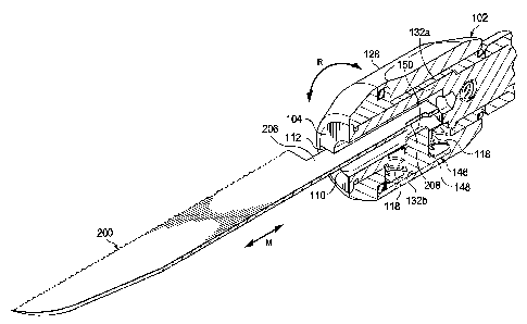
Referring now to Figs. 6A and 6B, top views of two exemplary flat-shanked
cutting blades for use with chuck 102 are shown. Beginning with Fig. 6A, blade
200 has a
cutting portion 202 with a serrated edge 204. It will be understood that other
cutting
shapes and structures may be used for cutting portion 202.
Blade 200 has a flattened shank 206 having an aperture 208 cut therethrough.
Aperture
208 is substantially sized to be complimentary to key portion 150 of securing
member 146.
Aperture 208 has two ends 208a and 208b that, in the example shown, are each
P0008634.01 CA 02729454 2010-12-23
WO 2010/002527
PCT/US2009/045486
5 substantially circular in shape and, here, are identical in shape.
According to one
embodiment, each end 208a and 208b may have a center point 209 and 211 and
circumferences 217 and 219. Radiuses 213 and 215 extend from center points 209
and
211, respectively. Ends 208a and 208b are spaced apart from one another by an
offset
distance 221. Thus, the distance between center points 209 and 211, is greater
than the
10 sum of radiuses 213 and 215 (see Fig. 6A).
As shown in Fig. 6B, a pair of inwardly directed ridges 223 may be provided
between circumferences 217 and 219, and which exclude portions of non-
complimentary
key portions. In one exemplary embodiment, the shank aperture and key portion
have
complimentary profiles which resemble an hourglass. In some embodiments, the
shank
aperture and key portion have a shape that is square, rectangular, dumbbell
shaped,
circular, scalloped, among others. In other embodiments, the profiles are non-
symmetrical
and may include a lateral bias such that the blade may be securable in only
one orientation.
For example, the aperture and key portion may be located lateral from axis L
such that the
aperture is an open notch in a side of the shank, rather than an enclosed
aperture. In yet
other embodiments, more than one aperture and more than one key portion permit
secure
and consistent blade alignment.
The shape of aperture 208 ensures that only a key having a substantially
complimentary shape can be disposed within the aperture. Thus, the chance of
blade 200
being used with an incompatible device having a non-complimentary key portion
is
reduced.
Referring now to Figs. 7A and 7B, cross-sectional views of blade 200 are
depicted
installed in chuck 102. Beginning with Fig. 7A, blade 200 is secured within
the chuck 102
by inserting shank 206 inside bore 110 so that flat shank 206 is retained
within slots 112.
Flat shank 206 has a width dimension greater than the diameter of central bore
110, and
therefore extends into, and is received within, slots 112.
Prior to insertion, camming sleeve 128 should be rotated in a direction
indicated by
rotation arrows R substantially to the position shown in Fig. 7A. In this
first position,
radially enlarged portion 132b of camming surface portion 132 is adjacent
contact head
P0008634.01 CA 02729454 2010-12-23
WO 2010/002527
PCT/US2009/045486
11
148 of securing member 146, thereby permitting springs 118 to bias securing
member 146
radially outward.
Turning now to Fig. 7B, camming sleeve 128 is then rotated so that radially
reduced portion 132a is located adjacent contact head 148. In this second
position,
securing member 146 is urged radially inward, which compresses springs 118 and
translates key portion 150 into blade aperture 208, thereby securing blade 200
within
chuck 102.
In one embodiment, chuck 102 is configured such that cam sleeve 128 may be
rotated through 180 degrees to completely translate the key portion between
the first
position and the second position. In other embodiments, chuck 102 is
configured such that
cam sleeve 128 may be rotated more or less than 180 degrees to translate the
key portion
between the first second positions. In one embodiment, chuck 102 is configured
for 90
degree rotation.
In one embodiment, cam sleeve 128 may be configured to be rotated perpetually
in
either the clockwise or counter-clockwise directions. Such perpetual
rotatability may
increase the ease of use for an operator. In other embodiments, one or more
stops may be
included so that rotation between the first and second positions is limited to
rotation
between the one or more stops.
In order to remove or replace a blade, or other tool within chuck 102, the
operations described here are essentially reversed. Camming sleeve 128 is
rotated so that
radially enlarged portion 132b of camming surface portion 132 is positioned
adjacent
contact head 148, thereby permitting the securing member 146 to be urged
radially
outward by springs 118 so that key portion 150 is removed from aperture 208.
Blade 200
can then be withdrawn from slots 112 and chuck 102.
As noted above, the securing, or locking of blade 200 is accomplished without
compressing or reducing a compressible collet against the blade. Thus,
according to one
embodiment, chuck 102 is a key-less chuck since a surgical tool may be
securely attached
to chuck 102 without wrenches, chuck keys, and the like. Neither is it
required to tighten
and loosen threads by hand, which threads may bind leading to delay in tool
change-over.
P0008634.01 CA 02729454 2010-12-23
WO 2010/002527
PCT/US2009/045486
12
In addition, slots 112 have upper and lower opposing inner surfaces 112a and
112b, as shown in Fig. 2. Opposing inner surfaces 112a and 112b are spaced
apart by a
slot width W that is substantially equal at all points between surfaces 112a
and 112b.
Thus, slot width W is substantially maintained at the same width whether the
tool is
secured or unsecured in the chuck.
Referring now to Fig. 8, an exemplary cutting blade 300 having a rounded shank
is
depicted. Blade 300 has a cutting portion 302 with serrated edge 304 that may
be similar
in configuration to cutting portion 202 and edge 204 described earlier. Blade
300 has a
rounded shank 306 which may have a pair of upper and lower cutaway portions
308a and
308b, respectively, at the proximal end of shank 306. Upper and lower cutaway
portions
308a and 308b define a flattened section 310. An aperture 312, which may be
shaped and
sized similar to aperture 208 described earlier, is disposed in flattened
section 310.
Thus, rounded shank 306 may have a first diameter, or first height, sized to
substantially fill cylindrical bore 110, and a second diameter, or second
height less than
the first height. The second height corresponds to the reduced thickness of
flattened
section 310 after portions 308a and 308b are cutaway. In other embodiments,
only one
side of rounded shank 306 is cutaway. This reduction in height provides a
unique
advantage, such that key protrusion 150 does not have to travel as far to
enter and exit the
shank aperture. Thus, the travel distance of key protrusion 150 between the
first and
second positions is reduced, allowing for a reduction in the maximum thickness
of
camming sleeve 128. Hence, the overall profile of chuck 102 may be reduced to
provide
better access, safety, and other benefits.
An additional benefit yielding from the reduced overall profile relates to the
mass
of the chuck. The rapid, repetitive direction change inherent to reciprocating
motion is
encumbered as more and more mass is added and made to quickly change
direction. Thus,
by reducing the mass profile of the chuck, the motor, transmission, and
dampening
features may all benefit from decreased wear, vibration, and power loss. In
addition, the
size and weight of the handpiece may be further reduced due to the reduced
loading. A
reduction in weight and vibration, along with improved balance may increase
user
accuracy and reduce user fatigue during surgical procedures.
P0008634.01 CA 02729454 2010-12-23
WO 2010/002527
PCT/US2009/045486
13
In other embodiments rounded shank 306 has no cutaways but extends its entire
length at
the first diameter.
Bore 110 and slots 112 of shaft 104 provide a receptacle that is capable of
receiving surgical tools having a substantially rounded shank cross-section,
such as blade
300, or a substantially flattened flat cross-section, such as blade 200.
Rounded shank 306
is sized and shaped to be retained within bore 110 of shaft 104. Thus, rounded
shank
blade 300 is inserted into bore 110 in substantially the same manner as blade
200,
however, no portion of shank 306 will be disposed within slots 112 of shaft
104. Blade
300 is similarly secured within chuck 102 by rotating camming sleeve 128 to
bias securing
member 146 radially inward so that key portion 150 passes through aperture 312
of shank
306. Blade 300 is also removed from chuck 102 in the same manner as blade 200.
Referring now to Fig. 9A, an exemplary rasp tool having a rounded shank is
depicted. Rasp tool 400 has a working portion 402 with rasp surface 404 Rasp
tool 400
has a rounded shank 406 which may have a pair of upper and lower cutaway
portions 408a
and 408b, respectively, at a proximal end of shank 406. Upper and lower
cutaway
portions 408a and 408b define a flattened section 410. An aperture 412, which
is shaped
and sized similar to aperture 208 described earlier, is disposed in flattened
section 410.
According to one exemplary embodiment shown in Fig. 9B, a rasp tool 420,
usable
in place of rasp tool 400, may include a rounded shank with pre-configured
bends or
contours, such as offset bends 414a and 414b. Thus, a proximal shank portion
416 is
generally aligned with a first longitudinal axis L1, and a distal shank
portion 418 is
generally aligned with second longitudinal axis L2. Axis L1 is generally
offset from axis
L2 by an offset distance D. An offset shank may be configured to promote
access and
visibility, though other shank configurations are contemplated, such as a
shank with a
single 90 degree bend transverse to axis L1, for example.
In some applications, it may preferable to have a round-shanked surgical tool
because the column strength is greater at extended distances. For example, a
long-reach
flat-shanked blade may be more prone to buckling than a similarly extended
round-
shanked blade. Other applications, not requiring an extended reach, may
require the thin
kerf and cutting efficiency of a flat-shanked blade. Thus, the novel chuck
disclosed offers
P0008634.01 CA 02729454 2010-12-23
WO 2010/002527
PCT/US2009/045486
14
an advantage to users who may now easily change between round- and flat-
shanked tools
without wrenches, special chuck keys, and the like.
In addition, procedures involving increased pressures, or alternating tool
force
directions¨such as may prevail in a rasping application¨may benefit from a
round shank.
A rasping tool may include a head that has more mass than a saw blade, such
that
increased pull-out forces act on the shank during the reciprocating
instrument's upstroke.
In such a situation, the present disclosure may offer an advantage over a
friction locking
collet, such as a split jaw collet, by providing a physical interference
locking protrusion
extending through the shank aperture that may resist such forces. In addition,
locking
protrusion 150 may prevent axial rotation of a rounded shank, especially axial
rotation of
an offset rounded shank, as shown in Fig. 9B. Working pressure applied to
working
portion 402 may be magnified by offset distance D to create a rotational
moment
introducing torque T about axis L1. Undesired axial rotation during a surgical
procedure
could be detrimental. However, according to this embodiment, locking
protrusion 150
structurally impedes rotational motion due to the torque T to keep rasp tool
400 from
spinning within the collet. Although the offset shank is shown on a rasp tool,
it is
understood that the offset shank may be used with any tool, including for
example, saw
blades, chisels, burs, and others.
In one embodiment a rounded shank may include one or more lateral extensions
which are longitudinally aligned but project radially outwardly from the outer
surface of
the shank. The lateral extensions may extend into existing slots 112 or into
additional
slots or key-ways, and may resemble, at least partially, the edges of a flat
shank. In other
embodiments, the lateral extensions may be bosses, or they may be formed from
key-
stock, for example.
It is further noted that in the embodiment shown, the chuck is a key-less
chuck.
Accordingly, the chuck is configured to lock and unlock the tool without
requiring a chuck
key or other tool component to aid with controlling the chuck. Instead, the
chuck may be
turned by hand, and may include flats or slight recesses that aid in gripping
the chuck with
a user's fingers. Either a flat- or round-shank tool may have anti-rotation
and anti-pullout
features for securing the tool in a key-less chuck, the aperture may have a
pair of side
P0008634.01 CA 02729454 2010-12-23
WO 2010/002527
PCT/US2009/045486
5 walls having a length with a width between them and distal and proximal
end walls. The
side wall length may be greater than the width between the side walls. Thus,
an anti-
rotation feature may comprise a flattened shank edge of a flat-shank blade or
the sidewalls
in an aperture of either type of shank. An anti-pullout feature may comprise
the proximal
end wall of an aperture of either type of shank.
10 It can be seen from the foregoing description that rotation of
camming sleeve 128
about retaining sleeve 122 will move securing member 146 between a first
position and a
second position. In the first position, key portion 150 is not substantially
withdrawn from
the receptacle of shaft 104 so that a surgical tool shank may be inserted or
removed
therefrom. In the second position, key portion 150 is disposed substantially
within the
15 receptacle of shaft 104 so that, if a surgical tool shank is present
within the receptacle, key
portion 150 will be disposed through the aperture of the surgical tool shank,
thereby
securing the tool within chuck 102.
In operation for reciprocating motion, instrument 10 is actuated by motor 15
to
move the blade, rasp, chisel, or other tool in a reciprocating manner
represented by motion
arrows M, as shown in Figs. 7A-9. Motor 15 rotates pinion gear 68 which, in
turn, rotates
eccentric crank 76. As crank 76 is rotated, its movement reciprocates
connecting rod 86
and reciprocating shaft 88, as well as chuck 102. It should be understood that
other
embodiments may provide reciprocating motion in other directions, such as
circular or
transverse directions.
In one exemplary embodiment, a round shank aperture and corresponding key
portion have complimentary profiles which resemble an hourglass. In other
embodiments,
the profiles are non-symmetrical and may include a lateral, bias or offset
such that the
blade may be securable in only one orientation. For example, the aperture and
key portion
may be located lateral from axis L such that the aperture is an open notch in
a side of the
shank, rather than an enclosed aperture. In yet other embodiments, more than
one aperture
and more than one key portion permit secure and consistent blade alignment.
These embodiments for varying features of the apertures and corresponding key
portions of either round- or flat-shank tools may provide proprietary
protection. For
example, an aperture configured with one of an hourglass shape, an
asymmetrical shape,
P0008634.01 CA 02729454 2010-12-23
WO 2010/002527
PCT/US2009/045486
16
and a longitudinal offset may prevent non-proprietary blades from being used
with the
disclosed chuck. Alternatively, corresponding variations to key portion
features may
prevent a non-proprietary chuck from being used with the disclosed surgical
tools.
While the invention has been shown in only one of its forms, it should be
apparent to those
skilled in the art that it is not so limited, but it is susceptible to various
changes without
departing from the scope of the invention.