Note : Les descriptions sont présentées dans la langue officielle dans laquelle elles ont été soumises.
CA 02731183 2013-04-30
=
76909-442
=
ERGONOMIC LIFT MECHANISM FOR A TRUCK BOX
BACKGROUND
1. Field of the Application
This invention relates to the field of storage containers for vehicles. More
particularly, the invention relates to a mechanism for ergonomically lifting a
toolbox or equipment from a storage box that is located in an area that is
difficult
to reach.
2. Description of the Related Art
Storage devices, more particularly truck boxes, are commonly used with
pickup trucks and vary in size, shape, finish, and efficiency. They are
typically
designed to integrate to the contours and cavities present in pick-up truck
beds
and are used to store and transport tools, hardware, and equipment used for
various projects. Because the truck boxes are often located in places that are
difficult to reach, such as the bed of a truck, it may be hard to access the
=
contents of the box without climbing into the truck bed.
Further, toolboxes are usually heavy due to the contents they carry. As a
result of the weight and the hard-to-reach location of the truck box in the
truck
bed, it is often difficult for a person to pull the toolbox or contents of the
toolbox
from the truck box.
It would be advantageous, therefore, to provide a mechanism for lifting the
contents of the truck box to facilitate the removal of the contents by a user.
These as well as other aspects and advantages will become apparent to
those of ordinary skill in the art by reading the following detailed
description, with
1
CA 02731183 2013-04-30
76909-442
reference where appropriate to the accompanying drawings. Further, it should
be understood
that the embodiments described in this summary and elsewhere are intended to
illustrate the
invention by way of example only.
SUMMARY
According to an aspect of the present invention, there is provided a truck box
assembly comprising: an outer box having a cover; a lifting mechanism, the
lifting mechanism
comprising: a tray adapted to support an inner container; a link coupled to
the cover and to the
tray for guiding the tray between an elevated position and a lowered position;
and a lift assist
coupled to an attachment point on the cover to assist in moving the tray
between the elevated
position and the lowered position.
According to another aspect of the present invention, there is provided a
truck
box assembly comprising: an outer box having a cover; a lifting mechanism, the
lifting
mechanism comprising: a tray adapted to support an inner container; a slotted
link coupled to
the cover and to the tray for guiding the tray between an elevated position
and a lowered
position; and a lift assist coupled to an attachment point on the cover to
assist in moving the
tray between the elevated position and the lowered position.
According to another aspect of the present invention, there is provided a
lifting
mechanism for use in a truck box having a cover adapted to be moved between an
open and a
closed position, the lifting mechanism comprising: a tray adapted to support
an inner
container contained within the truck box; a link coupled to the cover of the
truck box and to
the tray for guiding the tray between an elevated position and a lowered
position; and a lift
assist coupled to the cover to assist in lifting the tray from the lowered
position and lowering
the tray from the elevated position.
According to another aspect of the present invention, there is provided a
lifting
mechanism for use in a truck box having a cover adapted to be moved between an
open and a
closed position, the lifting mechanism comprising: a tray adapted to support
an inner
container contained within the truck box; a slotted link coupled to the cover
of the truck box
2
CA 02731183 2013-04-30
76909-442
and to the tray for guiding the tray between an elevated position and a
lowered position; and a
lift assist coupled to the cover to assist in lifting the tray from the
lowered position and
lowering the tray from the elevated position.
In one embodiment, the present application provides a truck box assembly
including an outer box having a cover and a lifting mechanism. The lifting
mechanism
includes a tray that supports the inner box, a first bracket mounted to a
bottom of the outer
box to allow the inner box to move between an elevated position and a lowered
position, and a
link coupled to the cover and to the tray for guiding the tray between the
elevated position and
the lowered position. The lifting mechanism may also include a lift assist
coupled to the cover
1 0 to assist in lifting and lowering the tray.
In yet another embodiment, the lifting mechanism comprises an L-shaped
slotted link coupled to the first bracket and to the tray for guiding the tray
between an elevated
position and a lowered position.
BRIEF DESCRIPTION OF THE DRAWINGS
Exemplary embodiments of the invention are described herein with reference
to the drawings, in which:
Figure 1 is a perspective view of a pickup truck including a truck box having
an ergonomic lift mechanism of an embodiment of the present invention;
Figure 2 is a perspective view of one embodiment of a truck box having an
ergonomic lift mechanism of an embodiment of the present invention;
Figure 3 is a perspective view of the mechanism shown in Figure 2 with a
portion of the truck box cut away;
Figure 4 is a side view of the mechanism shown in Figure 2 in the open
position;
Figure 5 is a side view of the mechanism shown in Figure 2 in the closed
2a
CA 02731183 2011-01-18
WO 2010/025063
PCT/US2009/054253
position;
Figure 6 is a perspective view of a second embodiment of a truck box
having an ergonomic lift mechanism of the present invention;
Figure 7 is a side view of the mechanism shown in Figure 6 in the open
position;
Figure 8 is a side view of the mechanism shown in Figure 6 in the closed
position;
Figure 9 is a perspective view of a third embodiment of a truck box having
an ergonomic lift mechanism of the present invention;
Figure 10 is a side view of the mechanism shown in Figure 9 in the open
position;
Figure 11 is a side view of the mechanism shown in Figure 9 in the closed
position;
Figure 12 is a perspective view of a fourth embodiment of a truck box
having an ergonomic lift mechanism of the present invention;
Figure 13 is a side view of the mechanism shown in Figure 12 in the open
position;
Figure 14 is a side view of the mechanism shown in Figure 12 in the closed
position;
Figure 15 is a perspective view of a fifth embodiment of a truck box having
an ergonomic lift mechanism of the present invention;
Figure 16 is a side view of the mechanism shown in Figure 15 in the open
position;
Figure 17 is a side view of the mechanism shown in Figure 15 in the closed
position; and
Figure 18 is a perspective view of another embodiment of a truck box
having an ergonomic lift mechanism with a single lift assist.
3
CA 02731183 2011-01-18
WO 2010/025063
PCT/US2009/054253
DETAILED DESCRIPTION
Truck boxes, such as truck box 10 shown in Figure 1, are generally
mounted in the bed of a pickup truck to store tools and other jobsite
accessories.
The truck box 10 has two horizontal ledges 10a, 10b which rest on opposite
side
rails of the bed of the truck to secure the truck box in place.
Referring to Figure 2, a first embodiment of an outer box, such as a truck
box 10, including an ergonomic lifting mechanism, generally indicated at 12,
is
shown in an open position. The truck box 10 has a cover 11, and an inner
container or box, such as a toolbox 14, located inside. The toolbox 14 may
hold
tools or any other type of equipment to be used at a jobsite. In the open
position,
the toolbox 14 is supported by a tray 16 which is part of the lifting
mechanism
12, the tray 16 being at an angle with respect to a bottom floor 13 of the
truck
box 10. The angle of the toolbox 14 in the open position may be in the range
of
approximately 25 to approximately 35 . In the closed position, the angle may
be
in the range of approximately 10 to approximately 15 .
The tray 16 may comprise a bottom portion 17 and at least one
upstanding side portion 18 to support the toolbox 14. The tray 16 may further
include a slot 19 on the upstanding side portion 18. The tray 16 may also
include
a second upstanding side portion (not shown) having a second slot (not shown)
located opposite the upstanding side portion 18. The tray 16 may further
include
a back portion 20. A bracket 15 may be positioned between the horizontal ledge
10a and the tray 16 to facilitate the guiding of the toolbox 14 in and out of
the
tray 16.
The lifting mechanism 12 further comprises a plurality of pivots mounted to
a bottom floor 13 of the truck box 10, as shown in Figure 3. The pivots may
include a first pair of brackets 21, 22 which support the back portion 20 of
the
tray 16 at a first end. Each bracket 21, 22 is provided with a pin that allows
the
tray 16 to pivot with respect to the brackets 21, 22. The plurality of pivots
further
may include a second pair of brackets 24, 26 which support a second end of the
tray, located at a distance away from the first end. Each of the brackets 21,
22,
4
CA 02731183 2011-01-18
WO 2010/025063
PCT/US2009/054253
24, and 26 are mounted to the bottom floor 13 of the truck box 10 by any known
suitable fastening mechanism, such as by welding, for example, or the use of
bolts, as another example. The first pair of brackets 21, 22 may have a
triangular
shape. Alternatively, the first pair of brackets may be any other type of
known
bracket.
Each bracket of the second pair of brackets 24, 26 is coupled to one end
28a, 30a of respective connecting links 28 and 30 so as to allow the links to
pivot
with respect to the bracket. Such a coupling can be achieved by the use of a
pin
provided on the bracket.
The connecting links 28, 30 each are provided with a pin 32, 34. The pin
32, 34 may slide along the slots 19 in the upstanding side portions 18 of the
tray
16 to allow for movement of the tray between its two positions.
The other end 28b, 30b of each connecting link 28, 30 is slidably secured
to a respective slotted bracket 36, 38 located on an underside of the cover 11
of
the truck box 10. The slotted brackets 36, 38 may be welded to the cover, or
alternatively, may be secured to the cover by any known fastening mechanism.
As the cover 11 is opened and closed, the connecting links 28, 30 slide along
respective slotted brackets 36, 38 and slots 19 on the upstanding side
portions
18 of the tray 16 to lift and lower the toolbox 14.
A third bracket 40 may be secured to the underside of the cover 11, as
shown in Figure 4. The third bracket is coupled to one end 42a of a lift
assist,
which may be in the form of a gas spring 42. Other known lift assist
mechanisms
which may be used include a compression spring, a tension spring, a pneumatic
cylinder, or a hydraulic cylinder, for example. The gas spring 42 is
preferably a
double acting gas spring; one such suitable gas spring is manufactured by
STABILUS. The other end 42b of the gas spring 42 may be secured to the truck
box 10 at fixed pivot 44.
The gas spring 42 assists in lifting the toolbox 14 when the cover 11 is
opened and in lowering the toolbox 14 when the cover 11 is closed. As the
cover
11 is opened and spring end 42a begins to move upwardly, gas spring 42 applies
CA 02731183 2011-01-18
WO 2010/025063
PCT/US2009/054253
a force (ranging between approximately 53 lbs. to approximately 98 lbs.) to
extend the spring from its compressed position. In order for the cover 11 to
stay
open, gas spring 42 applies a force (ranging between approximately 22 lbs. to
approximately 32 lbs.) to keep the gas spring in the extended position. Thus,
the
cover 11 remains open until it is acted upon by an external force in the
opposite
direction. When the external force in the opposite direction, such as a force
applied by a user, exceeds the force of the gas spring, the gas spring 42
begins
to retract back to its compressed position.
A second gas spring (shown in part in Figure 2) having a similar
configuration and mounting arrangement as gas spring 42 may also be located
opposite the gas spring 42 on the truck box 10 to assist in lifting and
lowering the
toolbox 14.
In operation, when the cover 11 of truck box 10 is in a closed position, as
shown in Figure 5, the toolbox 14 is in a lowered position and secured inside
of
the truck box. When the cover 11 is opened, as shown in Figure 4, the toolbox
14 is lifted up to an elevated position by the lifting mechanism 12 and
exposed for
easy access. In the elevated position, the toolbox 14 can easily be pulled out
of
the truck box 10 and loaded back into the truck box.
As the user opens the cover 11, the gas spring 42 is caused to move to
its extended position. As understood by those skilled in the art, the gas
stored
within the cylinder of the gas spring pushes against the one side of the
piston of
the gas spring, causing the cylinder to move away from the piston. This
movement assists in the opening of the cover 11 and the lifting of the tray 16
and
the toolbox 14 carried thereon from the lowered, stowed position to the
upward,
elevated position. The force of the gas spring 42 keeps the spring in the
extended position and keeps the cover 11 in the open position. The second gas
spring works as gas spring 42 to aid in lifting the cover 11 and keeping the
cover
11 in the open position.
Further, as the cover 11 is opened, one end 28b, 30b of each link 28, 30
is lifted and slides along respective slotted brackets 36, 38. This causes
pins 32,
6
CA 02731183 2011-01-18
WO 2010/025063
PCT/US2009/054253
34 to travel along the slots 19 in the upstanding side portions 18 of the tray
16,
thereby causing the bottom portion 17 and the back portion 20 of the tray 16
to
pivot about the first pair of brackets 21, 22 and rotate the toolbox 14 on an
angle
into an elevated position. The angle may be in the range of approximately 25
to
approximately 35 in the open position. With the tray at this elevated
position, the
user can remove the toolbox.
When the user pushes on the cover 11 to move it back into the closed
position, the gas spring 42 moves to its compressed position. As understood by
those skilled in the art, the gas stored within the cylinder of the gas spring
pushes
against the other side of the piston of the gas spring, causing the cylinder
to
move towards the piston. The return of the cover 11 to its closed position
causes
the connecting links 28, 30 to lower and slide back along respective slotted
brackets 36, 38 and slots 19 in the upstanding side portions 18 of the tray
16.
The toolbox 14 is thereby lowered back inside the truck box 10.
Figures 6-8 show a second embodiment of a lifting mechanism of the
present application. In this embodiment, the lifting mechanism, generally
indicated at 112, is located within truck box 110. The truck box 110 includes
a
cover 111. A toolbox 114 is located inside of the truck box 110 and is
supported
by a tray 116, the tray being at an angle in the open position. The angle of
the
toolbox 114 in the open position may be in the range of approximately 25 to
approximately 35 . In the closed position, the angle may be in the range of
approximately 0 to approximately 5 . The tray 116 may comprise a bottom
portion 117 and at least one upstanding side portion 118 to support the
toolbox
114. The tray 116 may further include a second upstanding side portion 119
located opposite the at least one upstanding side portion 118. The tray 116
may
also include a back portion 120.
The lifting mechanism 112 further comprises a first pair of brackets 121,
122 mounted to a bottom of the truck box 110. The first pair of brackets 121,
122 may each include a slot 123, 124. Each upstanding side portion 118, 119
of the tray 116 is provided with a pin that interacts with slots 123,124 to
allow
7
CA 02731183 2011-01-18
WO 2010/025063
PCT/US2009/054253
the tray to pivot and slide with respect to the brackets 121, 122.
A second pair of brackets 125, 126 may be secured to the underside of
the cover 111. A first pair of connecting links 128, 130 may be secured at one
end 128a, 130a to the second pair of brackets 125, 126. A second pair of
connecting links 129, 131 may be connected to the other end of the first pair
of
connecting links 128, 130, and may also include slots 132, 134, respectively.
A
pair of fixed pivots 136, 138 may be provided on either side of the truck box
110.
The fixed pivots 136, 138 are provided with a pin to interact with slots 132,
134
in the connecting links 129, 131. The other end 128b, 130b of connecting links
129, 131 may be pivotably mounted to the back portion 120 of the tray 116. In
an alternative embodiment, only one link may be provided between the brackets
125, 126 and the back portion of the tray 120.
The lifting mechanism 112 further includes a pair of vertical slotted
brackets 140, 142 attached to an end of the truck box 110 that is opposite the
back portion 120 of the tray 116, as shown in Figure 6. The slotted brackets
140, 142 may be welded to the side of the truck box 110, or alternatively, may
be attached to the truck box 110 by any suitable attachment means. The tray
116 is moved along brackets 140, 142 via pins provided on upstanding side
portions 118, 119 at one end of the tray.
A third bracket 144 may be mounted to the underside of the cover 111, as
shown in Figure 7. The third bracket 144 is coupled to one end 146a of a gas
spring 146. The gas spring 146 has similar characteristics as gas spring 42
described above. The other end 146b of gas spring 146 may be secured to the
truck box 110 at fixed pivot 148. The gas spring 146 assists in lifting the
toolbox
114 when the cover 111 is opened and lowering the toolbox 114 when the cover
is closed. A second gas spring 150 having a similar configuration and mounting
arrangement as gas spring 146 may also be located opposite the gas spring 146
on the truck box 110 to assist in lifting and lowering the toolbox 114.
In operation, when the cover 111 of truck box 110 is in a closed position,
as shown in Figure 8, the toolbox 114 is in a lowered position and secured
inside
8
CA 02731183 2011-01-18
WO 2010/025063
PCT/US2009/054253
of the truck box. When the cover 111 is opened, as shown in Figure 7, the
toolbox 114 is lifted up to an elevated position by the lifting mechanism 112
and
exposed for easy access. In the elevated position, the toolbox 114 can easily
be
pulled out of the truck box 110 and loaded back into the truck box.
As the user opens the cover 111, the gas spring 146 is caused to move to
its extended position. As understood by those skilled in the art, the gas
stored
within the cylinder of the gas spring pushes against the one side of the
piston of
the gas spring, causing the cylinder to move away from the piston. This
movement assists in the opening of the cover 111 and the lifting of the tray
116
and the toolbox 114 carried thereon from the lower, stowed position to the
upward elevated position. The force of the gas spring 146 keeps the spring in
the
extended position and keeps the cover 111 in the open position. The second gas
spring works as gas spring 146 to aid in lifting the cover 111 and keeping the
cover 111 in the open position.
Further, as the cover 111 is opened, the connecting links 128, 130 move
along with the cover 111, causing the links 129, 131 to move about the fixed
pivots 136, 138. This in turn causes the links 129, 131 to act on the back
portion 120 of the tray, which causes the tray to move along slots 123, 124 of
the first pair of brackets 121, 122, and along the slots of the brackets 140,
142.
This movement results in the tray 116 and the toolbox 114 being rotated on an
angle into the elevated position. The angle may be in the range of
approximately
25 to approximately 35 in the open position.
When the user pushes on the cover 111 to move it back into the closed
position, the gas spring 146 assumes its compressed position. As understood by
those skilled in the art, the gas stored within the cylinder of the gas spring
pushes
against the other side of piston of the gas spring, causing the cylinder to
move
towards the piston. The return of the cover 111 to its closed position causes
the
connecting links 128, 129, 130, 131 to be lowered and moved back to the
original position. The downward motion of the connecting links 129, 131 is
communicated to the back portion 120 of the tray 116, thereby causing the tray
9
CA 02731183 2011-01-18
WO 2010/025063
PCT/US2009/054253
116 to slide back along first pair of brackets 121, 122 and down the pair of
vertical slotted brackets 140, 142. Thus, the toolbox 114 is lowered back
inside
the truck box 110.
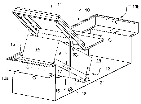
Figures 9-11 show a third embodiment of the lifting mechanism of the
present application. In this embodiment, the lifting mechanism, generally
indicated at 212, is located within truck box 210. The truck box 210 includes
a
cover 211. A toolbox 214 is located inside of the truck box 210 and is
supported
by a tray 216, the tray being at an angle with respect to a bottom of the
truck box
210 in the open position. The angle of the toolbox 214 in the open position
may
be in the range of approximately 20 to approximately 30 . In the closed
position,
the angle of the toolbox 214 is approximately 0 .
The tray 216 may comprise a bottom portion 217 and at least one
upstanding side portion 218 to support the toolbox 214. The tray 216 may
further include a second upstanding side portion 219 located opposite the at
least
one upstanding side portion 218. The tray 216 may also include a back portion
220.
The lifting mechanism 212 further comprises a pair of supports 221, 222
positioned on a bottom of the truck box 210. The pair of supports 221, 222 may
support the tray 216 when it is in a lowered position.
A first pair of brackets 224, 226 may be secured to the underside of the
cover 211. A pair of connecting links 228, 230 may be secured at one end
228a, 230a to the first pair of brackets 224, 226. Each connecting link 228,
230 may be L-shaped with a longitudinal slot 229, 231 extending along one of
its
sections, and each of the slots including a locking mechanism 233, 235. The
locking mechanism 233 can be best seen in Figure 11. In a preferred
embodiment, the locking mechanism constitutes an extension of the slot 229,
231, the extension being perpendicular to the axis that extends through the
longitudinal slot. Of course, the locking mechanism may take alternate forms.
The third embodiment further includes a pair of fixed pivots 232, 234 may
be provided on the truck box 210. The fixed pivots 232, 234 are operatively
CA 02731183 2011-01-18
WO 2010/025063
PCT/US2009/054253
coupled by respective pins to the slots 229, 231 and locking mechanisms 233,
235 of the connecting links 228, 230. The other end 228b, 230b of each
connecting link 228, 230 is secured to a respective upstanding side 218, 219
of
the tray 216 by any suitable mounting means.
A second bracket 236 may be secured to the underside of the cover 211,
as shown in Figure 10. The second bracket 236 is coupled to one end 238a of a
gas spring 238. The other end 238b of gas spring 238 may be secured to the
truck box 210 at fixed pivot 240. The gas spring 238 assists in lifting the
toolbox
214 when the cover 211 is opened and in lowering the toolbox 214 when the
cover 211 is closed. When compared to the embodiments discussed above, this
embodiment requires a gas spring of a higher capacity because the entire
weight
of the toolbox is carried by the cover.
The gas spring 238 assists in lifting the toolbox 214 when the cover 211
is opened and in lowering the toolbox 214 when the cover 211 is closed. As the
cover 211 is opened and spring end 238a begins to move upwardly, gas spring
238 applies a force (ranging between approximately 60 lbs. and approximately
120 lbs.) to extend the spring from its compressed position. In order for the
cover 211 to stay open, gas spring 238 applies a force (ranging between
approximately 22 lbs. and approximately 32 lbs.) to keep the gas spring in the
extended position. Thus, the cover 211 remains open until it is acted upon by
an
external force in the opposite direction. When the external force in the
opposite
direction, such as a force applied by a user, exceeds the force of the gas
spring,
the gas spring 238 begins to retract back to its compressed position.
A second gas spring 242 having a similar configuration and mounting
arrangement as gas spring 238 may also be located opposite the gas spring 238
on the truck box 210 to assist in lifting and lowering the toolbox 214.
The tray 216 may include a roller/handle 239 over which the toolbox 214
can roll as a user pulls it off of the tray 216. The roller 239 assists in
reducing
the friction when rolling out the toolbox 214 from the tray 216.
In operation, when the cover 211 of truck box 210 is in a closed position,
11
CA 02731183 2011-01-18
WO 2010/025063
PCT/US2009/054253
as shown in Figure 11, the toolbox 214 is in a lowered position and secured
inside
of the truck box. When the cover 211 is opened, as shown in Figure 10, the
toolbox 214 is lifted up to an elevated position by the lifting mechanism 212
and
exposed for easy access. In the elevated position, the toolbox 214 can easily
be
pulled out of the truck box 210 and loaded back into the truck box.
As the user opens the cover 211, the gas spring 238 is caused to move to
its extended position. As understood by those skilled in the art, the gas
stored
within the cylinder of the gas spring pushes against the one side of the
piston of
the gas spring, causing the cylinder to move away from the piston. This
movement assists in the opening of the cover 211 and the lifting of the tray
216
and the toolbox 214 carried thereon from the lower, stowed position to the
upward elevated position. The force of the gas spring 238 keeps the spring in
the
extended position and keeps the cover 211 in the open position. The second gas
spring 242 works as gas spring 238 to aid in lifting the cover 211 and keeping
the cover 211 in the open position.
Further, as the cover opens, the connecting links 228, 230 move
upwardly, past the fixed pivots 232, 234. Because the one end 228a, 230a of
the connecting links 228, 230 is fixed to brackets 224, 226, and the pivots
232,
234 are fixed, the tray 216 is lifted to an elevated position in which it is
at an
angle with respect to the bottom of the truck box. The angle may be in the
range
of approximately 20 to approximately 30 in the open position.
When the cover 211 is fully opened, the locking mechanism 233, 235 may
engage the fixed pivots 232, 234 to prevent accidental closure of the cover
211.
The user may pull on the roller/handle 239 to disengage the locking mechanism
233, 235 of the connecting links 228, 230 from the fixed pivots. The cover 211
is then moved back into the closed position, and the gas spring 238 assumes
its
compressed position. The toolbox 214 then descends back inside the truck box
210 as the cover 211 is closed.
Figures 12-14 show a fourth embodiment of the lifting mechanism of the
present application. In this embodiment, the lifting mechanism, generally
12
CA 02731183 2011-01-18
WO 2010/025063
PCT/US2009/054253
indicated at 312, is located within truck box 310. The truck box 310 includes
a
cover 311. A toolbox 314 is located inside of the truck box 310 and is
supported
by a tray 316, which is best seen in Figures 13 and 14. The tray 316 may
comprise a bottom portion (not shown) and at least one upstanding side portion
318 to support the toolbox 314. The tray 316 may further include a second
upstanding side portion (not shown) located opposite the at least one
upstanding
side 318. The tray 316 may also include a back portion 320.
Referring to Figure 12, the lifting mechanism 312 further comprises a first
pair of brackets 321, 322 secured to a bottom of the truck box 310. The first
pair of brackets 321, 322 may each include a slot 323, 324. Each of the first
pair of brackets 321, 322 may be operatively coupled to one end 326a, 328a of
a first pair of connecting links 326, 328 by a respective pin. The other end
326b,
328b of the connecting links 326, 328 is secured to the upstanding sides 318
of
the tray 316. A stabilizing link 330 may be provided to connect the two
connecting links 326, 328 and to provide stability to the links 326, 328.
A first gas spring 332 may be connected at one end 332a to the
stabilizing link 330 and at another end 332b to the bottom of the truck box
310 at
pivot 334. The first gas spring has similar characteristics as the gas spring
42
described above. The first gas spring 332 provides additional force to assist
in
lifting the toolbox 314 when the cover 311 is opened by pushing on the lifting
mechanism 312, and to assist in lowering the toolbox 314 when the cover 311 is
closed by pulling on the lifting mechanism 312.
A second pair of brackets 336, 338 may be secured to the underside of
the cover 311. A second pair of connecting links 340, 342 may be coupled at
one end 340a, 342a to the second pair of brackets 336, 338 and at another end
340b, 342b to the upstanding sides 318 of the tray 316. The second pair of
connecting links 340, 342 may be slidably connected to one end 344a, 346a of a
third pair of connecting links 344, 346. The two pairs of links are coupled by
an
interacting slot and pin arrangement. A pair of fixed pivots 348, 350 may be
secured to either side of the truck box 310 to support the other end 344b,
346b
13
CA 02731183 2011-01-18
WO 2010/025063
PCT/US2009/054253
of the third pair of connecting links 344, 346.
A third bracket 352 may be mounted to the underside of the cover 311, as
shown in Figure 13. The third bracket 352 is coupled to one end 354a of a
second gas spring 354. The second gas spring 354 has similar characteristics
as first gas spring 332 described above. The other end 354b of the second gas
spring 354 may be secured to the toolbox 314 at fixed pivot 356. The second
gas spring 354 assists in lifting the toolbox 314 when the cover 311 is opened
and lowering the toolbox 314 when the cover 311 is closed. A third gas spring
358 having a similar configuration and mounting arrangement as second gas
spring 354 may also be located opposite the second gas spring 354 on the truck
box 310 to assist in lifting and lowering the toolbox 314.
In operation, when the cover 311 of truck box 310 is in a closed position,
as shown in Figure 14, the toolbox 314 is in a lowered position and secured
inside
of the truck box. When the cover 311 is opened, as shown in Figure 13, the
toolbox 314 is lifted up to an elevated position by the lifting mechanism 312
and
exposed for easy access. In the elevated position, the toolbox 314 can easily
be
pulled out of the truck box 310 and loaded back into the truck box.
As the user opens the cover 311, the second gas spring 354 is caused to
move to its extended position. As understood by those skilled in the art, the
gas
stored within the cylinder of the gas spring pushes against the one side of
the
piston of the gas spring, causing the cylinder to move away from the piston.
This
movement assists in the opening of the cover 311 and the lifting of the tray
316
and the toolbox 314 carried thereon from the lower, stowed position to the
upward elevated position. The force of the gas spring 354 keeps the spring in
the
extended position and keeps the cover 311 in the open position. The third gas
spring 358 works as gas spring 354 to aid in lifting the cover 311 and keeping
the cover 311 in the open position.
Further, as the cover 311 is opened, the second connecting links 340,
342 are lifted up and pivoted along with the cover 311, thereby causing the
toolbox 314 and tray 316 to begin moving upward. As the cover 311 is opened,
14
CA 02731183 2011-01-18
WO 2010/025063
PCT/US2009/054253
the end 326b, 328b of first links 326, 328 connected to the tray 316 moves
upward while the other end 326a, 328a of the links 326, 328 moves along slots
323, 324 in brackets 321, 322. This causes the tray 316 to lift the toolbox
314
substantially straight upward in a vertical direction into the elevated
position. First
gas spring 332 assists in moving the toolbox 314 upwardly by applying an
additional upward force to link 330, thereby moving links 326, 328 upwardly.
Third links 344, 346 move upwardly along with links 340, 343, and stabilize
and
support second links 340 and 342 in the elevated position.
When the user pushes on the cover 311 to move it back into the closed
position, the gas springs 332, 354 assume their compressed positions. The
first
links 326, 328 move down and back along slots 323, 324. The third links 344,
346 move back down the slots in second links 340, 342, and second links 340,
342 slide back down to the original positions. The downward movement of links
326, 328 is assisted by gas spring 332. The toolbox 314 is thus lowered back
inside the truck box 310.
Figures 15-17 show a fifth embodiment of the lifting mechanism of the
present application. In this embodiment, the lifting mechanism, generally
indicated at 412 is located within truck box 410. The truck box 410 includes a
cover 411. A toolbox 414 is located inside of the truck box 410 and is
supported
by a tray 416 which is best seen in Figures 16 and 17. The tray 416 may
comprise a bottom portion (not shown) and at least one upstanding side portion
418 to support the toolbox 414. The tray 416 may further include a second
upstanding side portion (not shown) located opposite the at least one
upstanding
side 418. The tray 416 may also include a back portion 420.
The lifting mechanism 412 further comprises a first pair of brackets 421,
422 mounted to a bottom of the truck box 410. The first pair of brackets 421,
422 may each include a slot 423, 424. The first pair of brackets 421, 422 may
be operatively coupled to one end 426a, 428a of a first pair of connecting
links
426, 428 via pins. The other end 426b, 428b of the first pair of connecting
links
426, 428 may be secured to the upstanding sides 418 of the tray 416.
CA 02731183 2011-01-18
WO 2010/025063
PCT/US2009/054253
A second pair of connecting links 430, 432 may extend from the first pair
of connecting links 426, 428 at one end 430a, 432a. The other end 430b, 432b
of the second pair of connecting links 430, 432 is connected to a second pair
of
brackets 434, 436 secured to the bottom of the truck box 410. A stabilizing
link
438 may be provided to connect the second pair of connecting links 430, 432
and provide stability to the links 430, 432.
A first gas spring 440 may be connected at one end 440a to the
stabilizing link 438 and at the opposite end 440b to the bottom of the truck
box
410 at pivot 442. The first gas spring has similar characteristics as gas
spring
42 described above. The first gas spring 440 provides additional force to
assist
in lifting the toolbox 414 when the cover 411 is opened by pushing on the
lifting
mechanism 412, and to assist in lowering the toolbox 414 when the cover 411 is
closed by pulling on the lifting mechanism 412.
A third pair of brackets 444, 446 may be mounted to the underside of the
cover 411. The third pair of brackets is coupled to one end 448a, 450a of a
third
pair of connecting links 448, 450. The opposite end 448b, 450b of the third
pair
of connecting links 448, 450 may be coupled to the upstanding sides 418 of the
tray 416.
A fourth bracket 452 may be secured to the underside of the cover 411,
as shown in Figure 16. The fourth bracket 452 is coupled to one end of a
second
gas spring 454. The second gas spring 454 has similar characteristics as first
gas spring 440 described above. The other end of the second gas spring 454
may be secured to the truck box 410 at fixed pivot 456. The second gas spring
454 assists in lifting the toolbox 414 when the cover 411 is opened and
lowering
the toolbox when the cover 411 is closed. A third gas spring 458 having a
similar
configuration and mounting arrangement as second gas spring 454 may also be
located opposite the second gas spring 454 on the truck box 410 to assist in
lifting and lowering the toolbox 414.
In operation, when the cover 411 of truck box 410 is in a closed position,
as shown in Figure 17, the toolbox 414 is in a lowered position and secured
inside
16
CA 02731183 2011-01-18
WO 2010/025063
PCT/US2009/054253
of the truck box. When the cover 411 is opened, as shown in Figure 16, the
toolbox 414 is lifted up to an elevated position by the lifting mechanism 412
and
exposed for easy access. In the elevated position, the toolbox 414 can easily
be
pulled out of the truck box 410 and loaded back in.
As the user opens the cover 411, the second gas spring 454 is caused to
move to its extended position. As understood by those skilled in the art, the
gas
stored within the cylinder of the gas spring pushes against the one side of
the
piston of the gas spring, causing the cylinder to move away from the piston.
This
movement assists in the opening of the cover 411 and the lifting of the tray
416
and the toolbox 414 carried thereon from the lower, stowed position to the
upward elevated position. The force of the gas spring 454 keeps the spring in
the
extended position and keeps the cover 411 in the open position. The third gas
spring 458 works as second gas spring 454 to aid in lifting the toolbox 414
and
keeps the cover 411 in the open position.
Further, as the cover 411 is opened, the connecting links 448, 450 pivot
along with the cover 411, which lifts the toolbox 414 and tray 416 up. As the
toolbox 414 moves up, first links 426, 428 move along slots 423, 424 in
brackets 421, 422. This causes the second links 430, 432 to move upward.
The upward movement of the second links 430, 432 is assisted by first gas
spring 440. The movement of the links 426, 428, 430, and 432 causes the tray
416 to lift the toolbox 414 substantially straight upward in a vertical
direction into
the elevated position.
When the user pushes on the cover 411 to move it back into the closed
position, the gas springs 440, 454 assume their compressed positions. The
downward movement of the cover 411 causes links 448, 450 to move
downwardly, and also causes links 426, 428 to move downwardly and to slide
back along slots 423, 424. The movement of links 426, 428 in turn causes links
430, 432 to move downwardly. The downward movement of links 430, 432 is
assisted by gas spring 440. Thus, the toolbox 414 is lowered back inside the
truck box 410.
17
CA 02731183 2013-04-30
76909-442
The embodiments discussed above are provided with two gas springs
positioned along either side of the cover. It is possible to utilize a single
gas
spring 500 to lift and lower the tray and toolbox, as shown in the alternate
embodiment of Figure 18. The single gas spring 500 may be mounted to the
center of the cover 511 at one end and to the center of the body of the truck
box
510 at the other end to ensure a balanced force.
The various embodiments of the present invention are depicted with a gas
spring as a lift assist. The lift assist could take alternate forms such as a
pneumatic cylinder, a hydraulic cylinder, a compression spring, or a tension
spring, for example. Furthermore, each embodiment could also include only lift
assist connected to the cover to assist in lifting and lowering the cover and
the
tray, as described above and shown in Figure 18.
It should be understood that the components of the lifting mechanism are
not limited to the embodiments shown. Additional components that could be
included in the lifting mechanism include tension springs, fulcrums, bearings,
and
stoppers.
Furthermore, it should be understood that the pairs of brackets mentioned
above may take alternate forms, provided that the toolbox and cover are
allowed
to move as required. For example, the brackets 21, 22 could take the form of a
single member that extends across the side portions of the tray. Similarly,
brackets 24, 26 could take the form of a single bracket.
In addition, it should be understood that while Figure 1 depicts only a single
lifting mechanism, a second lifting mechanism could be provided on the other
side
of the truck box. Further, the lifting mechanism is not limited in its
application to
the particular truck box depicted in Figure 1. The invention can be applied in
other
designs of truck boxes.
While certain features and embodiments of the present application have
been described in detail herein, it is to be understood that the application
encompasses all modifications and enhancements within the scope of the
following claims.
18