Note : Les descriptions sont présentées dans la langue officielle dans laquelle elles ont été soumises.
CA 02732776 2011-01-31
Title: POWER GENERATION APPARATUS
Technical Field
[1] The present invention relates to a power generation apparatus, and
in particular to a power generation apparatus which can efficiently generate
electric power even when a small amount of fluid is supplied from the outside.
Background Art
[2] A power generation apparatus which is intended to use hydraulic
to power is basically directed to generating power when the fluid externally
supplied from the outside directly collides with a turbine. The power
generation
apparatus which uses turbine needs fluid which should be supplied by as much
amount as the fluid helps generate a power exceeding a friction force or an
inertia force between mechanical elements. So, when the amount of fluid does
not exceeds a certain level, it is impossible to generate power.
[3]
[4] In case of turbine, since an electric power is generated by means of
an impact force generated when fluid collides with blades, energy loss
increased in the course of collisions, which results in a lower power
generation
efficiency.
CA 02732776 2011-01-31
Disclosure of Invention
[5] Accordingly, it is an object of the present invention to provide a
power generation apparatus which can keep generating power even when a
small amount of fluid is supplied.
[6] To achieve the above objects, there is provided a power generation
apparatus, comprising a weight load which is movable upwards and
downwards; a movable storage tank guide box which includes a storage part at
its upper side for collecting fluid from a fluid supply part, a fluid
discharge part
to provided at its lower side, and a supply opening and closing part for
selectively
discharging the fluid gathered at the fluid storage part; a movable storage
part
which is accommodated at the movable storage tank guide box and is movable
upward and downwards between the fluid storage part and the fluid discharge
part and includes a retrieval opening and closing part for selectively
discharging
1s the fluid collected via the supply opening and closing part at a portion
close to
the fluid storage part to the fluid discharge part at a portion close to the
fluid
discharge part; and a power transfer unit which connects the movable storage
tank and the weight load in a way of transferring power and moves the movable
storage tank downwards when the weight load moves upwards, and moves the
20 movable storage tank upwards when the weight load moves downwards.
CA 02732776 2011-01-31
[7] The power generation apparatus further comprises a weight load
guide box in which the weight load is accommodated and is movable upwards
and downwards; and a fluid transfer part which is provided at a lower side of
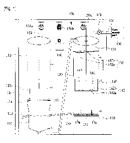
either the weight load guide box or the movable storage tank guide box and is
connected with the fluid discharge part in a way that fluid can flow and
pressurizes the fluid inputted from the fluid discharge part with the aid of
either
the weight load or the self-weight of the movable storage tank and transfers
the
pressurized fluid to the fluid storage part via the transfer pipe.
[8] The fluid transfer part is provided at a lower side of the weight load
io guide box and communicates with the fluid discharge part via the retrieval
pipe
so that the fluid of the fluid transfer part is pressurized by means of the
self-
weight of the weight load, and the fluid of the fluid discharge part can be
inputted.
[9] In addition, the power generation apparatus a supply opening and
closing member which is provided at the movable storage tank so that the
movable storage tank can allow the supply opening and closing part to open at
a portion close to the fluid storage part; and a retrieval opening member
which
is provided at the fluid discharge part so that the movable storage tank can
allow the retrieval opening and closing member to open at a portion close to
the
fluid discharge part, and the supply opening and closing part comprises a
CA 02732776 2011-01-31
supply hole formed at the bottom of the fluid storage part; and a supply
opening
and closing part which is rotatably installed at the bottom of the fluid
storage
part for closing the supply hole with the aid of self-weight and rotates
upwards
with the aid of the supply opening member and allows the supply hole to open,
and the retrieval opening and closing part comprises a retrieval hole formed
at
the bottom of the movable storage tank; and a retrieval opening member which
is rotatably installed at the bottom of the movable storage tank for closing
the
retrieval hole with the aid of self-weight and rotates upwards with the aid of
the
retrieval opening member and allows the retrieval hole to open.
[10] The fluid transfer part comprises a contractible member which
includes an opening for inputting the fluid supplied from the retrieval pipe
into
the interior and becomes contractible by means of the weight load and
transfers
the fluid inputted into the interior via the opening to the fluid storage part
via the
transfer pipe; and a blocking member which is rotatably installed at the
contractible member for selectively opening and closing the opening and moves
depending on the movement of the weight load for thereby selectively opening
and closing the opening.
[11] The power generation apparatus further comprises a supply
maintaining unit which limits the downward movements of the movable storage
tank for the same to be maintained at a portion close to the fluid storing
part
CA 02732776 2011-01-31
until fluid is inputted from the fluid storage part into the movable storage
tank by
above a certain reference amount and releases the downward movement limit
of the movable storage tank when the fluid is applied to the movable storage
tank by above a certain reference amount; and a discharge maintaining unit
which limits the upward movements of the movable storage tank for the fluid to
keep discharging until fluid becomes below a certain reference level at a
portion
close to the fluid discharge part and releases the upward movement limit of
the
movable storage tank when the fluid of the movable storage tank becomes
below a certain reference level.
[12] The supply maintaining unit comprises a supply slide member
which is slidable in upward and downward directions in the interior of the
movable storage tank guide box; a supply slide spring which applies a
tensional
force for pulling the supply slide member upwards; a supply rotation member
which is rotatably installed in upward and downward directions at an end
portion
is of the supply slide member; a supply stopper which is slidable at the
supply
slide member in a radius direction of the movable storage tank guide box and
selectively limits the operation that the supply rotation member rotates
downwards; a supply stopper spring which pressurizes the supply stopper in a
direction of the center of the movable storage tank guide box; a supply pullet
which is provided at the other end portion of the supply slide member 271; and
CA 02732776 2011-01-31
a supply wire of which one end is connected with the movable storage tank
guide box, and the other end is fixed at the supply stopper 274 for thereby
releasing the downward rotation limit of the supply rotation member by moving
the supply stopper toward an outer surface of the movable storage tank guide
box when the supply slide member moves downwards; and the discharge
maintaining unit comprises a discharge slide member which is slidable in
upward and downward directions in the interior of the movable storage tank
guide box; a discharge slide spring which applies a tensional force to the
discharge slide member so that the discharge slide member can be pulled
to upwards and pressurizes the slide member downwards when the discharge
slide member moves upwards; a discharge rotation member which is rotatable
in upward and downward directions at an end portion of the discharge slide
member; a rotation return elastic member which returns the discharge rotation
member to an original position in a state that the discharge rotation member
has
moved downwards; a discharge stopper which limits the discharge rotation
member to rotate upwards; a discharge stopper spring which pressurizes the
discharge stopper in the direction of the center of the movable storage tank
guide box; a discharge pulley which is provided at the other end portion of
the
discharge slide member; and a discharge wire of which one end is fixed at the
movable storage guide box in a way of surrounding part of the discharge slide
CA 02732776 2011-01-31
member, and the other end portion is fixed at the discharge stopper for
thereby
obtaining an upward rotation of the discharge rotation member by moving the
discharge stopper in an outer surface direction of the movable storage tank
guide box when the discharge slide member moves upwards while overcoming
the elastic force of the discharge slide spring.
[13] According to an example of the present invention, the power
transfer unit comprises at least one pulley; and a power transfer wire which
surrounds at least part of the pulley and of which one end portion is fixed at
the
weight load, and the other end portion is fixed at the movable storage tank.
[14] According to another example of the present invention, the power
transfer unit comprises a first rack gear of which one end portion is fixed at
the
weight load; a second rack gear of which one end portion is fixed at the
movable storage tank; and a plurality of power transfer gears which are
engaged with the first and second rack gears, respectively, so that the weight
load moves upwards when the movable storage tank moves downwards, and
the weight load moves downwards when the movable storage tank moves
upwards.
[15] The retrieval pipe opening and closing unit is installed in the interior
of the movable storage tank guide box and is movable in upward and downward
directions and comprises an opening and closing member and includes an
CA 02732776 2011-01-31
opening and closing member for selectively blocking the retrieval pipe
depending on the upward and downward movements of the movable storage
tank; and an elastic member which is provided at the opening and closing
member and applies an elastic operation in a direction that the retrieval pipe
opens.
[16] There is further provided a buoyancy member which is provided at
the bottom of the movable storage tank and moves upwards with the aid of the
fluid gathered at the fluid discharge part as the retrieval pipe is blocked by
means of the opening and closing member.
[17] A spacer is provided at the bottom of the movable storage tank for
allowing the fluid of the movable storage tank to input into the retrieval
pipe via
the retrieval opening and closing part by maintaining a certain space between
the bottom of the movable storage tank and the bottom of the fluid discharge
part.
[18] There is provided a fluid transfer part of the power generation
apparatus, which communicates with the fluid storage part via the transfer
pipe
and is provided at a lower side of the movable storage tank guide box and is
connected with the fluid discharge part in a way of fluid transfer, wherein
the
fluid inputted from the fluid discharge part into the fluid transfer part is
pressurized by means of the self-weight of the movable storage tank and is
CA 02732776 2011-01-31
transferred to the fluid storage part via the transfer pipe.
[19] The supply maintaining unit and the discharge maintaining unit can
be electronically controlled, and there are provided a first fluid detection
sensor
which is downwardly protruded from the fluid storage part for thereby
detecting
the water level of the fluid filled in the movable storage tank; a second
fluid
detection sensor which is provided at the fluid discharge part for thereby
detecting the water level of the fluid remaining in the movable storage tank;
and
a controller which controls the supply maintaining unit so that the downward
movement of the movable storage tank is possible when the water level of the
to movable storage tank detected by the first fluid detection sensor is above
a
certain reference level, and controls the discharge maintaining unit so that
the
upward movement of the movable storage tank is possible when the water level
of the movable storage tank detected by the second fluid detection sensor is
below a certain reference value.
[20] The power generation apparatus can be installed at sea, and in this
case the fluid supply part becomes sea water. In this case, the fluid storage
part
may include an inlet part for inputting seawater with the aid of the water
waves.
[21] The inlet part comprises an inlet port provided at the fluid storage
part for inputting water; and an opening and closing door for selectively
opening
and closing the inlet port depending on the amount of the water inputted into
the
CA 02732776 2011-01-31
fluid storage part.
[22] When the power generation apparatus is installed at sea, the power
generation apparatus comprises a forced discharge part for collecting the
fluid
inputted from the movable storage tank to the fluid discharge part; a water
level
detection sensor for detecting the water level of the forced discharge part; a
pump for transferring the fluid of the forced discharge part to the outside
when
the water level of the forced discharge part detected by the water level
detection
sensor exceeds a certain reference value; and a check valve for preventing the
water from reversely inputting into the forced discharge part.
[23] To achieve the above objects, there is provided a power generation
apparatus which comprises a weight load guide box; a weight load which is
accommodated in the weight load guide box and is movable in upward and
downward directions; a movable storage tank guide box which includes a fluid
storage part at its upper side, a supply opening and closing part formed at
the
bottom of the fluid storage part for selectively discharging the fluid
gathered at
the fluid storage part, and a fluid discharge part formed at its lower side; a
movable storage tank which is accommodated in the movable storage tank
guide box so that it can reciprocate in upward and downward directions
between the fluid storage part and the fluid discharge part, and includes a
retrieval opening and closing part for selectively discharging the fluid
gathered
CA 02732776 2011-01-31
via the supply opening and closing part at a portion close to the fluid
storage
part toward the fluid discharge part at a portion close to the fluid discharge
part;
a power transfer unit which connects the movable storage tank and the weight
load in a way of transferring power and moves the movable storage tank
downwards when the weight load moves upwards, and moves the movable
storage tank upwards when the weight load moves downwards; and a fluid
transfer part which is provided at a lower side of the weight load guide box
and
communicates with the fluid storage part via the transfer pipe and
communicates with the fluid discharge part via the retrieval pipe, wherein the
io fluid transfer part pressurizes the fluid inputted from the fluid discharge
part via
the retrieval pipe with the aid of the self-weight of the weight load and
supplies
to the fluid storage part via the transfer pipe.
Advantageous effects
[24] With the above troubleshooting means, it is possible to reliably
generate power even when a small amount of fluid is supplied in such a manner
that fluid is stored in a movable storage tank, the fluid stored in the fluid
storage
tank is moved to a movable storage tank.
[25] Since the fluid transferred from a fluid transfer part to a fluid
storage part is supplied along with the fluid of a fluid supply part, it is
possible to
CA 02732776 2011-01-31
generate power even when the amount of fluid in a fluid supply part is
relatively
smaller.
[26] The fluid is collected at the fluid storage part by a certain amount,
and then is supplied to the movable storage tank, so it is possible to enhance
a
down movement of the movable storage tank, which leads to enhancing power
generation efficiency.
[27] Since the fluid of the fluid transfer part is pressurized by a weight
load or a self-weight of a movable storage tank and is supplied to the fluid
storage part for thereby enhancing power generation efficiency.
[28] A supply opening and closing part of a fluid storage part and a
retrieval opening and closing part can be opened by using a supply opening
member used so as to open a supply opening and closing part of a fluid storage
part and a retrieval opening and closing member, so it is possible to enhance
a
power generation efficiency because an additional power is not used when
controlling an opening and closing member.
[29] Since a supply opening and close member of a supply opening and
closing part and a retrieval opening and closing member of a retrieval opening
and closing part close a supply hole and a retrieval hole, respectively, with
the
aid of self-weights, it is possible to minimize the power to be used for
controlling
the power generation apparatus.
CA 02732776 2011-01-31
[30] A fluid transfer part consists of an extendable member and a
blockage member, by which it is possible to minimize a friction force between
a
weight load used for pressurizing the fluid transfer part and a weight load
guide
box, which leads to enhancing power generation efficiency.
[31] The weight load can be for a movable storage tank to move up and
down by means of a supply maintaining unit and a discharge maintaining unit,
and a up and down motion of a movable storage tank can be enhanced by the
same. A higher power can be transferred to the outside with the aid of
enhanced
up and down motions of the movable storage tank, and a higher power
1o (corresponding to energy which can be generated per unit hour) can be
produced.
[32] Since a power transfer unit is made of a rack gear and a plurality of
power transfer gears, an up motion generated by means of a movable storage
tank can be converted into an up motion power. The fluid can gather at a fluid
discharge part by blocking a retrieval pipe when the movable storage tank is
positioned close to the fluid discharge part, and the movable storage tank can
move up by means of a buoyancy of the gathered fluid, which leads to
maximizing the efficiency of power generation.
[33] The movable storage tank and the fluid discharge part are made
spaced apart by installing a spacer member at the fluid discharge part for
CA 02732776 2011-01-31
thereby efficiently discharging fluid from the movable storage tank.
Brief Description of the Drawings
The present invention will become better understood with reference to
the accompanying drawings which are given only by way of illustration and thus
are not limitative of the present invention, wherein;
[34] Figures 1 to 8 are various schematic views of a power generation
apparatuses according to a first embodiment of the present invention, while
describing a power generation procedure;
[35] Figure 9 is a schematic view illustrating a power generation
apparatus according a second embodiment of the present invention;
[36] Figure 10 is a schematic perspective view illustrating a fluid transfer
part of Figure 9;
[37] Figures 11 to 15 are schematic views illustrating a supply
maintaining unit of Figure 9, while describing an operation of a supply
maintaining unit;
[38] Figures 16 to 20 are schematic views illustrating a discharge
maintaining unit of Figure 9, while describing an operation of a discharge
maintaining unit;
[39] Figure 21 is a schematic view illustrating a driving force transfer unit
CA 02732776 2011-01-31
of a power generation apparatus according to a third embodiment of the present
invention;
[40] Figure 22 is a schematic view illustrating a retrieval opening and
closing unit of a driving force generation apparatus according to a third
embodiment of the present invention;
[41] Figure 23 is a schematic view illustrating a power generation
apparatus according to a fourth embodiment of the present invention;
[42] Figure 24 is a schematic view illustrating a power generation
apparatus according to a fifth embodiment of the present invention;
[43] Figures 25 to 27 are schematic views illustrating a power generation
apparatus according to a sixth embodiment of the present invention, while
describing a moving operation of a movable storage tank;
[44] Figures 28 to 30 are views for describing an operation of a supply
maintaining unit of Figure 25;
[45] Figures 31 to 33 are views for describing an operation of a discharge
maintaining unit of Figure 25;
[46] Figure 34 is a block diagram illustrating a control operation of a
supply maintaining unit and a discharge maintaining unit of Figure 25;
[47] Figure 35 is a schematic view illustrating a power generation
apparatus according to a seventh embodiment of the present invention;
CA 02732776 2011-01-31
[48] Figures 36 to 38 are views for describing an operation of an inlet part
of Figure 35;
[49] Figure 39 is a schematic view illustrating a power generation
apparatus according to an eighth embodiment of the present invention; and
[50] Figure 40 is a schematic view illustrating a power generation
apparatus according to a ninth embodiment of the present invention.
Modes for carrying out the invention
[51] The power generation apparatus according to the preferred
to embodiments of the present invention will be described.
[52] As shown in Figure 1, the power generation apparatus according to
a first embodiment of the present invention comprises a weight load guide box
110, a weight load 120 which is movable up and down in the interior of the
weight load guide box 110, a movable storage tank guide box 130 disposed
close to the weight load guide box 110, a movable storage tank 140 which is
movable in up and down directions in the interior of the movable storage tank
guide box 130, and a power transfer unit 150 which drivingly connects the
weight load 120 and the movable storage tank 140.
[53] The weight load guide box 110 guides the up and down movements
of the weight load 120. A fluid transfer part 111 is provided at a lower side
of the
CA 02732776 2011-01-31
weight load transfer guide box 110, and the fluid transfer part 111 is
connected
with the movable storage tank guide box 130 via a transfer pipe 112 and is
connected with a fluid discharge part 133 of a lower side of the movable
storage
tank guide box 130 via a retrieval pipe 135. The fluid transfer part 111 is to
supply the fluid received from the fluid discharge part 133 via the retrieval
pipe
135 to the fluid storage part 131, and the fluid of the fluid transfer part
111 is
pressurized by means of the self-weight of the weight load 120 and is supplied
to the fluid storage part 131 via the transfer pipe 112.
[54] The weight load 120 is used to help cause a seesaw motion along
io with the movable storage tank 140 and is heavier than the movable storage
tank 140 when fluid is not in the movable storage tank 140, and is lighter
than
the movable storage tank 140 when a certain amount of fluid is filled in the
movable storage tank 140. So, the weight load 120 and the movable storage
tank 140 moves like a seesaw motion depending on the weight of the fluid in
the
movable storage tank 140.
[55] A sealing protrusion part 121 is provided at an outer surface of the
weight load 120 for transferring the fluid of the fluid transfer part 111 to
the fluid
storage part 131 of the movable storage tank guide box 130 via the transfer
pipe 112. The fluid transfer part 111 has a diameter smaller than the diameter
of
the weight load guide box 110, so the sealing protrusion part 121 can do like
a
CA 02732776 2011-01-31
piston movement. The diameter except for the fluid transfer part 111 of the
weight load guide box 110 is larger than the sealing protrusion part 121,
which
makes it possible to minimize the loss of energy due to a friction force in
the
course of up and down motions of the weight load 120, by which it is possible
to
increase a pressurizing force to be used for transferring the fluid in the
fluid
transfer part 111, and it is possible to increase the amount of fluid which is
to be
transferred from the fluid transfer part 111 to the fluid storage part 131. In
addition, a sealing protrusion part 121 is formed at an outer surface of the
weight load 131. It is possible to maximize the application of the position
energy
io of the weight load 120 by pressurizing the fluid of the fluid transfer part
111
while maintaining a sealed state with the inner wall of the fluid transfer
part 111.
[56] An initial position maintaining part 114 is formed at an inner wall of
the weight load guide box 110 for the weight load 120 to be positioned at an
initial position. The initial position maintaining part 114 is used to support
the
weight load 120 under the circumference that the power generation apparatus is
not driven. When the power generation apparatus starts operating, a person can
manually release the initial position maintaining part 114 by rotating an
externally installed lever as well as can automatically release the initial
position
maintaining part 114 by transferring a signal by a switch or something to a
motor
driving or a driving cylinder or a solenoid driving part.
CA 02732776 2011-01-31
[57] The movable storage tank guide box 130 is to guide an up and
down movement of the movable storage tank 140 and includes a fluid storage
part 131 at its upper portion for gathering a certain amount of fluid and
supplying to the movable storage tank 140, and a fluid discharge part 133 at
its
lower portion for discharging the fluid stored in the movable storage tank
140.
[58] The fluid storage part 131 is provided at an upper side of the
movable storage tank guide box 130 for gathering a certain amount of the fluid
and supplying to the movable storage tank 140. Fluid from the fluid transfer
part
111 and the fluid from an external fluid supply 100 are gathered in the fluid
io storage part 131. As the fluid of the fluid transfer part 111 is supplied
to the fluid
storage part 131, it is possible to reduce the amount of fluid supplied from
the
external fluid supply part 100, which means that it is possible to generate
power
with the external fluid supply part 100 with a small amount of fluid supply.
[59] The fluid supply part 100 might be formed of a storage tank for
storing underwater via pumping, a storage tank generally installed at an
apartment building or a high rise place or a storage tank for receiving water
from
a river, a dam or a valley and storing the same. The supply pipe 101 for
supplying the fluid of the fluid supply part 100 to the fluid storage part 131
is
equipped with a stop valve 102. The stop valve 102 can be manually closed or
opened or can operate in response to an electric signal. When the stop valve
CA 02732776 2011-01-31
102 is designed to operate in response to an electric signal, a water level
detection sensor (not shown) is installed at the fluid storage part 131 for
thereby
automatically controlling the stop valve 102 depending on the amount of fluid
stored in the fluid storage part 131 detected by means of the water level
detection sensor (not shown). Namely, when the water level of the fluid stored
in
the fluid storage part 131 is below a first reference amount, the stop 102 is
opened for thereby supplying the fluid of the fluid supply part 100 to the
fluid
storage part 131, and when the water level of the fluid stored in the fluid
storage
part 131 is above a second reference amount, the stop valve 102 is closed for
io thereby stopping the supply of the fluid of the fluid supply part 100 to
the fluid
storage part 131, which can be automatically controlled.
[60] A supply opening and closing part 132 is prepared at the bottom of
the fluid storage part 131 for supplying stored fluid to the movable storage
tank
140. The supply opening and closing part 132 comprises a supply hole 132a
formed at the bottom of the fluid storage part 131 and a supply opening and
closing member 132b for selectively opening and closing the supply hole 132a.
Here, the supply opening and closing member 132b is rotatably installed at the
bottom of the fluid storage part 131. The movable storage tank 140 moves
upward and rotate in an upward direction while being pushed by the supply
opening and closing member 143 provided at the movable storage tank 140 for
CA 02732776 2011-01-31
thereby opening the supply hole 132a, and when the movable storage tank 140
moves downward, it rotates downwards by its self-weight for thereby closing
the
supply hole 132a. When the movable storage tank 140 moves downward, and
the supply opening member 143 is spaced apart from the supply opening and
closing member 132b, the supply opening and closing member 132b does not
directly close the supply hole 132a because the supply opening and closing
member 132b remains floated by means of the buoyancy of the fluid in the fluid
storage part 131. Therefore, even when the movable storage tank 140 moves
downwards, and the supply opening member 143 is spaced apart from the
to supply opening and closing member 132b, the fluid of the fluid storage part
131
drops free while keeping supplying to the movable storage tank 140.
[61] The bottom of the fluid storage part 131 is inclined toward the
supply hole 132a so as to efficiently use the fluid by making the fluid
supplied to
the fluid storage part 131 more efficiently flow via the supply hole 132a.
is [62] The fluid discharge part 133 is provided at a lower side of the
movable storage tank guide box 130 for thereby discharging the fluid gathered
at the movable storage tank 140 and transferring the discharged fluid to the
fluid
transfer part 111 while communicating with the fluid transfer part 111 and the
retrieval pipe 135, respectively. A spacer member 136 is provided at the
bottom
20 of the fluid discharge part 133 for making the discharge of the movable
storage
CA 02732776 2011-01-31
tank 140 easier by spacing the movable storage tank 140 and the bottom of the
fluid discharge part 133. At the fluid discharge part 133 is provided a
retrieval
opening member 134 for opening the retrieval opening and closing part 142 of
the movable storage tank 140.
[63] The movable storage tank 140 has a weigh changing depending on
the amount of the collected fluid for thereby performing a seesaw motion with
the aid of the weight load 120 and the power transfer unit 150. At the movable
storage tank 140 is installed an accommodation part 141 for gathering fluid,
and
at the bottom of the accommodation part 141 is provided a retrieval opening
io and closing part 142 for selectively discharging the fluid gathered at the
accommodation part 141. At the movable storage tank 140 is provided a supply
opening member 143 for selectively opening and closing the supply opening
and closing member 132b.
[64] The retrieval opening and closing part 142 comprises a retrieval
hole 142a formed at the bottom of the accommodation part 141, and a retrieval
opening and closing member 142b which is rotatably installed at the bottom of
the accommodation part 141 for selectively opening and closing the retrieval
hole 142a. The retrieval opening and closing member 142b is pulled by the
retrieval opening member 134 for thereby opening the retrieval hole 142a, and
when the movable storage tank 140 moves upward, and the retrieval opening
CA 02732776 2011-01-31
member 134 is spaced apart from the retrieval opening and closing member
142b, the retrieval opening and closing member 142b rotates downwards with
the aid of self-weight for thereby opening the retrieval hole 142a.
[65] The power transfer unit 150 is provided so as to connect the weight
load 120 and the movable storage tank 140 for transferring power between the
same and comprises a plurality of pulleys 151a, 151b and 151c and a power
transfer wire 152 of which one end is connected with the weight load 120, and
the other end is connected with the movable storage tank 140. With the above
construction, when the weight load 120 is heavier than the movable storage
tank 140, the weight load 120 moves downwards, whereas the movable storage
tank 140 moves upwards. When the fluid is filled in the accommodation part 141
of the movable storage tank 140, and the movable storage tank 140 is heavier
than the weight load 120, the movable storage tank 140 moves downwards, and
the weight load 120 moves upwards.
[66] The puller 151b is connected with a power conversion apparatus
160 for converting the kinetic energy of the power transfer wire 152 into
electric
energy. The power conversion apparatus might comprise an electric generator
or something for generating electric energy.
[67] The operation of the power generation apparatus having the above
elements will be described.
CA 02732776 2011-01-31
[68] As shown in Figure 1, when the power generation apparatus is not
intended to operate, the weight load 120 is fixed in the interior of the
weight load
guide box 110 by means of the initial position maintaining part 114, and the
accommodation part 141 of the movable storage tank 140 remains empty. In the
above state, as shown in Figure 2, when the initial position maintaining part
114
is released by a manual or automatic way, the weight load 120 moves
downwards because it is heavier than the movable storage tank 140, and the
movable storage tank 140 moves upwards by means of the power transfer wire
152. When the weight load 120 moves downwards and pressurizes the fluid
io gathered at the fluid transfer part 111, the fluid of the fluid transfer
part 111
moves upwards via the transfer pipe 112 and is supplied to the fluid storage
part
131. The cross sectional area of the fluid transfer part 111 is much larger
than
the cross sectional area of the transfer pipe 112, the surface level of the
fluid of
the transfer pipe 112 might be formed at a much higher position than the
surface level of the fluid of the fluid transfer part 111 which is pressurized
by
means of the weight load 120 based on Pascal's principle, and the fluid of the
transfer pipe 112 flows via the upper side of the transfer pipe 112 and is
supplied to the fluid storage part 131.
[69] As shown in Figure 2, the stop valve 102 is opened manually or in
accordance with an external electric signal, so the fluid of the fluid supply
part
CA 02732776 2011-01-31
100 is stored in the fluid storage part 131.
[70] As shown in Figure 3, when the weight load 120 continues to move
downwards and stops by the housing of the fluid transfer part 111, and the
movable storage tank 140 keeps moving upwards, and the supply opening
member 143 of the movable storage tank 140 pushes upwards the supply
opening and closing member 132b for thereby opening the supply hole 132a.
The fluid stored in the fluid storage part 131 is gathered at the movable
storage
tank 140 via the supply hold 132a.
[71] As shown in Figure 4, when a certain amount of fluid is supplied to
io the movable storage tank 140 and the weight of the movable storage tank 140
becomes heavier than the weight load 120, the movable storage tank 140 starts
getting moved downwards. Even when the movable storage tank 140 starts
getting moved, the supply opening and closing member 132b keeps the supply
hole 132a opened by means of the buoyancy of the fluid gathered at the fluid
is storage part 131, by which the movable storage tank 140 keeps receiving the
fluid from the fluid storage tank 131 while moving downwards. The downward
moving speed of the movable storage tank 140 is getting increased more and
more, and the acceleration of the movable storage tank 140 is getting
increased
more and more.
20 [72] As shown in Figure 5, when all of the fluid of the fluid storage part
CA 02732776 2011-01-31
131 is discharged toward the accommodation part 141 of the movable storage
tank 140, the supply opening and closing member 132b of the fluid storage part
131 rotates downwards for thereby blocking the supply hole 132a. At this time,
the stop valve 102 is opened, and the fluid of the fluid supply part 100 is
supplied to the fluid storage part 131.
[73] As shown in Figure 6, when the movable storage tank 140 keeps
moving downwards and approaches close to the bottom of the fluid discharge
part 133, the retrieval opening member 134 of the fluid discharge part 133
pushes upwards the retrieval opening and closing member 142b for hereby
to opening the retrieval hole 142a. The fluid gathered at the accommodation
part
141 of the movable storage tank 140 is drained toward the fluid discharge part
133, and the drained fluid is filled again into the fluid transfer part 111
via the
retrieval pipe 135.
[74] As shown in Figure 7, when the amount of the fluid remaining in the
accommodation part 141 of the movable storage tank 140 is below a certain
reference level, the movable storage tank 140 becomes lighter than the weight
load 120. At this moment, the movable storage tank 140 starts moving upwards
again with the aid of the downward motion of the weight load 120. When the
fluid discharged toward the fluid transfer part 111 via the retrieval pipe 135
exceeds a certain amount, it discharges to the outside via the retrieval pipe
113.
CA 02732776 2011-01-31
[75] As shown in Figure 8, when the movable storage tank 140 moves
upwards, the retrieval opening member 134 becomes spaced apart from the
retrieval opening and closing member 142b, but the retrieval opening and
closing member 142b does not fully close the retrieval hole 142a due to the
buoyancy of the fluid remaining in the movable storage tank 140. Namely, the
retrieval opening and closing member 142b fully closes the retrieval hole 142a
after the fluid of the movable storage tank 140 is all discharged toward the
fluid
discharge part 133, after which the routines 2 to 7 are repeatedly performed.
[76] The fluid stored in the fluid storage part 111 is supplied to the fluid
io storage part 131 in addition to the fluid supplied from the external fluid
supply
part 100 for thereby generating power even when the amount of the fluid from
the fluid supply part 100 is small.
[77] In the above embodiment of the present invention, the occasion
that the fluid of the fluid transfer part 111 is transferred to the fluid
storage part
131 with the aid of the weight load 120, but when the amount of the fluid by
the
weight load 120 is less or when it is needed to reduce the supply time of the
fluid, it is possible to forcibly transfer the fluid of the fluid transfer
part 111 to the
fluid storage part 131 by using a pump or something.
[78] Figures 9 to 20 are schematic views of a power generation
apparatus according to a second embodiment of the present invention.
CA 02732776 2011-01-31
[79] As shown in Figure 9, the power generation apparatus according to
a second embodiment of the present invention, as compared to the first
embodiment of the present invention, the structure of the fluid transfer part
211
has been changed, and the supply maintaining unit 270 and the discharge
maintaining unit 280 are further added, and the brake apparatus 290 is further
added to limit the movement of a supply maintaining wire 152. Since the
structures and operations are same as the first embodiment except for the
above mentioned differences, only the different matters will be described. In
the
following descriptions, while the second embodiment is described, the same
io elements as the first embodiment will be given the same reference numerals
in
the second embodiment of the present invention.
[80] As shown in Figures 9 and 10, the fluid transfer part 211 comprises
a contractible member 212, a blocking member 214 and an elastic member 215.
[81] The contractible member 212 is contracted with the aid of the self-
is weight of the weight load 120 when the weight load 120 moves downwards and
returns to its original position with the aid of its self-elastic force. At
one side of
the contractible member 212 is provided an opening 213 for introducing fluid.
[82] The blocking member 214 blocks the opening 213 so that the
interior of the contractible member 212 keeps sealed state when the
contractible
20 member 212 is contracted. The blocking member 214 slides along the
CA 02732776 2011-01-31
contractible member 212 for selectively blocking the opening 213.
[83] The elastic member 215 is provided to return the blocking member
214 to its original position. When it is pressed by the weight load 120 after
blocking the opening 213, and the weight load 120 moves upwards, the
blocking member 214 moves upwards so as to open the opening 213 with the
aid of the elastic force of the elastic member 215. As shown in Figure 10, the
elastic member 215 is disposed between the contractible member 212 and the
blocking member 214.
[84] The operation of the fluid transfer part 211 having the above
io construction will be described. As shown in Figure 10, in a state that the
weight
load 120 is spaced apart from the contractible member 212, the contractible
member 212 becomes an extended state, and the opening 213 remains open.
So, the fluid supplied via the retrieval pipe 135 can be inputted into the
interior
of the contractible member 212 via the opening 213.
[85] In the above state, when the weight load 120 moves downwards,
the weight load 120 presses the blocking member 213. When the elastic
member 215 is compressed, the blocking member 214 moves downwards and
blocks the opening 213. The weight load 120 keeps moving downwards, and
the weight load 120 pressurizes the contractible member 212 for thereby
contracting the same. The fluid in the contractible member 212 is compressed
CA 02732776 2011-01-31
and transferred to the fluid storage part 131 via the transfer pipe 112. When
the
weight load 120 moves upwards, the contractible member 212 is extended with
the aid of its self-elastic force and returns to the state as shown in Figure
10.
The blocking member 214 moves upwards with the aid of the elastic force of the
elastic member 215 for thereby opening the opening 213.
[86] Since the contractible member 212 is used for the fluid transfer part
211, the weight load 120 does not contact with the inner wall of the fluid
transfer
part 211 of the weight load guide box 110, and the power loss can be prevented
due to the friction of the same for thereby enhancing the efficiency of the
power
io generation apparatus.
[87] As shown in Figures 11 to 15, the supply maintaining unit 270 is
provided so as to limit the downward movement timing of the movable storage
tank 140 and is installed at an inner surface of the movable storage tank
guide
box 130. In more particular, the supply maintaining unit 270 comprises a
supply
slide member 271 which slides in up and down directions in the interior of the
movable storage tank guide box 130, a supply slide spring 272 which provides a
tensional force so that the supply slide member 271 can be upwardly pulled, a
supply rotation member 273 which is rotatably installed at an end of the
supply
slide member 271, a supply stopper 274 which limits a downward rotation of the
supply rotation member 273, a supply stopper spring 275 which pressurizes the
CA 02732776 2011-01-31
supply stopper 274 toward the outside, a supply pulley 276 which is provided
at
the other end of the supply slide member 271, and a supply wire 277 of which
one end is fixed at the movable storage tank guide box 130, and the other end
is fixed at the supply stopper 274.
[88] The operation of the supply maintaining unit 270 will be described.
As shown in Figure 11, in a state that the movable storage 140 does not
contact
with the supply rotation member 273 while being moving upwards, as shown in
Figure 12, when the movable storage tank 140 moves upwards and pushes
upwards the supply rotation member 273, the supply rotation member 273
io rotates upwards, and as shown in Figure 13, the movable storage tank 140
passes over the supply maintaining unit 270. When the upward movement of
the movable storage tank 140 is finished, the supply rotation member 273, as
shown in Figure 14, returns to its original position by means of a self-
weight.
The fluid of the fluid storage part 131 is gathered into the accommodation
part
141 of the movable storage tank 140. When the movable storage tank 140
becomes heavier than the weight load 120, the movable storage tank 140 starts
moving downwards and comes into contact with the supply rotation member
273 and is supported. At this time, the downward rotation of the supply
rotation
member 273 is limited by means of the supply stopper 274. So, the supply
rotation member 273 limits the downward movement of the movable storage
CA 02732776 2011-01-31
tank 140.
[89] In the above state, the fluid of the fluid storage part 131 is supplied
to the movable storage tank 140, and the weight of the movable storage tank
140 is getting increased more and more. When the weight of the movable
storage tank 140 exceeds the elastic force of the supply slide spring 272, the
supply slide spring 272 starts extending, and the supply slide member 271
starts moving downwards. At this time, one end of the supply wire 277 is fixed
at
the movable storage tank guide box 130, so the supply wire 277 keeps pulling
the supply stopper 274 in an inward direction. So, the supply stopper 274
io moves inwards, and the supply rotation member 273 starts rotating
downwards.
When the supply rotation member 273 rotates downwards, the movable storage
tank 140 starts moving downwards.
[90] The downward movement of the movable storage tank 140 is
limited by means of the supply rotation member 273 until the weight of the
same
becomes larger than the elastic force of the supply slide spring 272 and
starts
downward moving after the fluid is filled in the movable storage tank 140 more
than a certain reference amount. So, it is possible to increase the down
movement speed of the movable storage tank 140, which results in enhancing
power generation efficiency.
[91] The discharge maintaining unit 280 discharges the fluid until the
CA 02732776 2011-01-31
fluid of the movable storage tank 140 remains below a certain reference level
and allows the movable storage tank 140 to move upwards for thereby
enhancing the upward movement speed of the movable storage tank 140. The
discharge maintaining unit 280 is has a similar structure with the supply
maintaining unit 270.
[92] In more details, the discharge maintaining unit 280 comprises a
discharge slide member 281 which slides in upward and downward directions in
the interior of the movable storage tank guide box 130, a discharge slide
spring
282 which applies a tensional force for upwardly pulling the discharge slide
io member 281, a discharge rotation member 283 which is rotatably installed at
an
end portion of the discharge slide member 281, a rotation return elastic
member
284 which returns the discharge rotation member 283 to its original position,
a
discharge stopper 285 which limits the upward rotation of the discharge
rotation
member 283, a discharge stopper spring 286 which pressurizes the discharge
stopper 285 toward the outside, a discharge pulley 287 which is provided at
the
other end portion of the discharge slide member 281, and a discharge wire 288
of which one end is fixed at the movable storage tank guide box 130, and the
other end portion is fixed at the discharge stopper 285.
[93] The operation of the discharge maintaining unit 280 will be
described. As shown in Figure 16, when the movable storage tank 140 moves
CA 02732776 2011-01-31
downwards and comes into contact with the discharge rotation member 283 and
pressurizes the same in the downward direction, as shown in Figure 17, the
discharge rotation member 283 rotates downwards overcoming the elastic force
of the rotation return elastic member 284. As shown in Figure 18, the movable
storage tank 140 passes through the discharge maintaining unit 280 and moves
downwards. The discharge rotation member 283 returns to its original position
with the aid of the rotation return elastic member 284 after it passes through
the
discharge maintaining unit 280.
[94] The fluid of the movable storage tank 140 starts discharging toward
io the fluid discharge part 133. When the fluid of the movable storage tank
140
discharges by a certain amount, and the weight of the movable storage tank
140 becomes lighter than the weight load 120, the movable storage tank 140
moves upwards again. As shown in Figure 19, when the upward movement of
the movable storage tank 140 is limited by means of the discharge rotation
member 283 of which upward rotation has been limited by means of the
discharge stopper 285. So, the movable storage tank 140 keeps discharging
fluid toward the fluid discharge part 133 while coming into contact with the
discharge rotation member 283. A difference of the weights of the movable
storage tank 140 and the weight load 120 increases, so the force allows the
movable storage tank 140 to move upwards increases.
CA 02732776 2011-01-31
[95] When the upward movement force of the movable storage tank 140
increases and exceeds the elastic force of the discharge slide spring 282, as
shown in Figure 19, the discharge slide member 281 slides upwards while
compressing the discharge slide spring 282. At this time, one end of the
discharge wire 288 is fixed at the movable storage tank guide box 130, so the
discharge wire 288 pulls the discharge stopper 285, and as shown in Figure 20,
the discharge rotation member 283 becomes a state that it can rotate upwards.
So, the movable storage tank 140 can push the discharge rotation member 283.
[96] The discharge stopper 285 returns to its original position with the
to aid of the elastic force of the discharge stopper spring 286 and returns to
the
state of Figure 16, and the discharge rotation member 283 returns to its
original
position by means of the self-weight and the rotation return elastic member
284,
respectively.
[97] The upward movement of the movable storage tank 140 can be
limited until the weight of the fluid remaining in the accommodation part 141
becomes a certain level, and at the time when a difference between the weights
of the movable storage tank 140 and the weight load 120 is large at the rising
time of the movable storage tank 140, the rising speed of the movable storage
tank 140 is enhanced, which leads to enhancing power generation efficiency.
[98] In the present embodiment of the present invention, the example
CA 02732776 2011-01-31
that the supply maintaining unit 270 and the discharge maintaining unit 280
have operated mechanically, but the supply maintaining unit 270 and the
discharge maintaining unit 280 might be electrically operated by detecting a
water level of the movable storage tank 140.
[99] The brake apparatus 290 limits the movement of the power transfer
wire 152 while preventing the movable storage tank 140 and the weight load
120 from falling down and might be formed of various brake apparatuses such
as hydraulic or pneumatic brake systems, an electric brake system or
something.
[100] Figures 21 and 22 are schematic views of the major elements of
the power generation apparatus according to a third embodiment of the present
invention.
[101] As shown in Figure 21, the power generation unit 350 of the
power generation apparatus according to a third embodiment of the present
invention comprises a plurality of power transfer gears 351a, 351b, 351c and
351d, and first and second rack gears 352 and 353, which are different from
the
first and second embodiments of the present invention.
[102] The lower side of the first rack gear 352 is fixed to the weight load
120, and the lower side of the second rack gear 353 is fixed to the movable
storage tank 140. The first and second rack gears 352 and 353 are engaged
CA 02732776 2011-01-31
with the power transfer gears 351a, 351b, 351c respectively. The numbers of
the power transfer gears 351a, 351b, 351c are determined in such a manner
that the first and second rack gears 352 and 353 are to move in opposite
directions from each other. Namely, an odd number of the power transfer gears
351 a, 351 b and 351 c should be used.
[103] It is possible to generate power by a rising force of the movable
storage tank 140 differently from the power transfer wire 152 by connecting
the
weight load 120 and the movable storage tank 140 by using a plurality of
gears.
In the present embodiment, the movable storage tank 140 can rise with the aid
io of the rising force by the buoyancy at the fluid discharge part 133 in
addition to
the rising force by means of the self-weight of the weight load 120.
[104] As shown in Figure 22, a buoyancy member 370 is attached to the
bottom of the movable storage tank 140. A retrieval pipe opening and closing
unit 354 is provided at a lower side of the movable storage tank guide box 130
for selectively opening and closing the retrieval pipe 135 in cooperation with
the
up and down movements of the movable storage tank 140.
[105] The retrieval pipe opening and closing unit 354 comprises an
opening and closing member 356 which is movable in up and down directions in
the interior of the movable storage tank guide box 130, and an elastic member
355 of which one end portion is fixed at the movable storage tank guide box
130
CA 02732776 2011-01-31
for applying an elastic tensional force to the opening and closing member 356,
and the other end portion is fixed to the opening and closing member 356.
[106] The opening and closing member 356 comprises a sync operation
part 356a for selectively coming into pressurized contact depending on the up
and down movements of the movable storage tank 140, and the blocking part
356b comprises a blocking part 356b for selectively blocking.
[107] The operation of the retrieval pipe opening and closing unit 354
with the above construction will be described. First of all, when the movable
storage tank 140 moves downwards and comes into contact with the sync
io operation part 356a for thereby pressurizing the sync operation part 356a
in a
downward direction. The opening and closing member 356 moves downwards,
and the blocking member 356b blocks the retrieval pipe 135. In the above
state,
the retrieval hole 142a of the movable storage tank 140 becomes open, and the
fluid of the movable storage tank 140 is discharged to the fluid discharge
part
133. At this time, since the retrieval pipe 135 is blocked, the discharging
fluid is
gathered at the fluid discharge part 133. The gathered fluid operates
providing a
buoyancy to the buoyancy member 370 of the movable storage tank 140 for
thereby moving upwards the movable storage tank 140. The movable storage
tank 140 rises with the aid of the rising force of the weight load 120 and the
rising force of the buoyancy for thereby generating a relatively larger power
via
CA 02732776 2011-01-31
the second rack gear 353, which results in enhancing the power generation
efficiency.
[108] When the movable storage tank 356 rises, the opening and
closing member 356 returns to its original position by means of an elastic
force
of the elastic member 355, and the fluid of the fluid discharge part 133 is
transferred to the fluid transfer part 111 via the retrieval pipe 135.
[109] Figure 23 is a schematic view illustrating the power generation
apparatus according to a fourth embodiment of the present invention. In the
fourth embodiment of the present invention differently from the second
to embodiment, the fluid transfer part 411 is formed at a lower side of the
movable
storage tank guide box 130, and the drain pipe 413 is connected with the
movable storage tank guide box 130. The retrieval pipe 135 of the second
embodiment of the present invention is removed. The transfer pipe 411 is
connected with the fluid storing part 131 from the fluid transfer part 411,
and the
fluid of the fluid transfer part 411 pressurized by means of the movable
storage
tank 140 is transferred to the fluid storage part 131.
[110] At the bottom of the weight load guide box 110 is provided an
impact releasing member 415 for preventing any impact by means of the weight
load 120.
[111] The fluid discharged from the movable storage tank 140 to the
CA 02732776 2011-01-31
fluid discharge part 433 by means of the weight of the movable storage tank
140 is transferred to the fluid transfer part 411. The other operations are
same
as the second embodiment, so the detailed descriptions will be omitted.
[112] Figure 24 is a schematic view of a power generation apparatus
according to a fifth embodiment of the present invention.
[113] As shown in Figure 24, in the fifth embodiment of the present
invention, the fluid transfer part 211 and the transfer pipe are removed from
the
second embodiment of the present invention. The power generation apparatus
according to the fifth embodiment of the present invention is characterized in
io that the fluid from the fluid supply part 100 fills in the fluid storage
part 131 by a
certain amount, and then the movable storage tank 140 rises, and the fluid of
the fluid storage part 131 fills into the movable storage tank 140. With the
above
construction, even when the amount of the fluid from the fluid storage tank
140
is small, since it is first filled into the fluid storage part 131 by a
certain amount,
and then it filled into the movable storage tank 140, it is possible to
generate a
high power.
[114] The seesaw motions of the weight load 120 and the movable
storage tank 140 and the operations of the supply maintaining unit 270 and the
discharge maintaining unit 280 are same as the second embodiment of the
present invention, so the detailed descriptions will be omitted.
CA 02732776 2011-01-31
[115] In the present embodiment, the occasion that there is provided a
weight load guide box 110 has been described. Even when the weight load
guide box 110 is not present, any construction that a certain amount of the
fluid
is first filled in the fluid storage part 131 and then the fluid is filled in
the movable
storage tank 140 might be applied to the present invention.
[116] Figures 25 to 34 are schematic views of a power generation
apparatus according to a sixth embodiment of the present invention.
[117] As shown in Figures 25 and 34, the sixth embodiment of the
present invention is different from the second embodiment in view that the
to supply maintaining unit 270 and the discharge maintaining unit 280 operate
in
accordance with an electric signal.
[118] In the sixth embodiment of the present invention, the supply
maintaining unit 670 and the discharge maintaining unit 680 are different from
the second embodiment, and the first and second fluid detection sensors 691
and 692, the tank detection sensor 693 and the controller 694 are further
provided.
[119] The supply maintaining unit 670 of the sixth embodiment of the
present invention, as shown in Figures 28 to 30, comprises a supply support
member 671, a supply stopper 672, a supply stopper spring 673, a supply pullet
674, a supply wire 675 and a supply driving motor 676.
CA 02732776 2011-01-31
[120] The supply support member 671 is installed being supported by
the movable storage tank guide box 130 for thereby supporting the remaining
elements of the supply maintaining unit 670.
[121] The supply stopper 672 is installed at the supply support member
671 while being slidable in a radius direction of the movable storage tank
guide
box 130 for thereby selectively limiting the down movement of the movable
storage tank 140. The supply stopper 672 remains pressurized at the supply
stopper spring 673 in the direction of the center of the movable storage tank
guide box 130. At an end portion is provided a contact part 672a having an
to inclined surface 672b so that the supply stopper 672 can be pushed
outwardly
by means of the movable storage tank 140 when the movable storage tank 140
moves upwards.
[122] The supply pulley 674 is to guide the supply wire 675 and is
provided at the supply support member 671 in multiple numbers.
[123] The supply wire 675 is connected with its one end being
connected to the supply driving motor 676, the other end being connected to
the
supply stopper 672. When the supply driving motor 676 is driven in the
direction
that the supply wire 675 is wound, the supply wire 675 slides the supply
stopper
672 toward the outside while overcoming the elastic force of the supply
stopper
spring 673. The movable storage tank 140, of which the down movement is
CA 02732776 2011-01-31
limited by means of the supply stopper 672, can descend. In the present
invention, it is shown like the supply wire 675 is positioned at a portion
where it
is interred when the movable storage tank 140 moves, but the supply wire 675
is positioned where the movement of the movable storage tank 140 is not
interfered with.
[124] The discharge maintaining unit 680 has similar constructions and
operations with the supply maintaining unit 670. In more details, as shown in
Figures 31 to 33, the discharge maintaining unit 680 comprises a discharge
support member 681, a discharge stopper 682, a discharge stopper spring 683,
io a discharge pulley 684, a discharge wire 685 and a discharge driving motor
686.
[125] The discharge support member 681 is disposed at a lower side of
the supply support member 671 and is supported by the movable storage tank
guide box 130 while supporting the remaining elements of the discharge
maintaining unit 680.
[126] The discharge stopper 682 is installed at the discharge support
member 681 while being slidable in the radius direction of the movable storage
tank guide box 130 for thereby selectively limiting the rising movement of the
movable storage tank 140. The discharge stopper 682 remains at the discharge
stopper spring 683 while being pressurized in the center direction of the
movable storage tank guide box 130. At an end portion of the discharge stopper
CA 02732776 2011-01-31
682 is provided a contact part 682a having an inclined surface 682b so that
the
discharge stopper 682 can be pushed outwardly be means of the movable
storage tank 140.
[127] The discharge pulley 684 is to guide the discharge wire 685 and is
provided at the discharge support member 681 in multiple numbers.
[128] The discharge wire 685 is installed, with its one end being
connected with the discharge driving motor 686, with its other end being
connected with the discharge stopper 682. When the discharge driving motor
686 is driven in the direction that the discharge wire 685 is wound, the
to discharge wire 685 slides the discharge stopper 682 in the direction of the
outside while overcoming the elastic force of the discharge stopper spring
683.
So, the movable storage tank 140 of which the upward movement is limited by
means of the discharge stopper 682 can rise. In the present embodiment, the
movable storage tank 140 is positioned as being interfered with when the
is movable storage tank 140 moves, but the discharge wire 685 is positioned
while
not being interfered with the movement of the movable storage tank 140.
[129] The first fluid detection sensor 691 is to detect whether or not the
fluid of the fluid storage part 131 is filled in the movable storage tank 140
by a
certain level. As shown in Figures 25 to 27, it is installed below the fluid
storage
20 part 131. In more particular, the first fluid detection sensor 691 outputs
an ON
CA 02732776 2011-01-31
signal to the controller 694 when the fluid is filled in the movable storage
tank
140 by a certain amount. So the controller 694 drives the supply driving motor
676 and moves the supply stopper 672 to the outside. So, the movable storage
tank 676 starts moving downwards.
[130] The second fluid detection sensor 692 is to detect whether or not
the movable storage tank 140 has discharged all the fluid from the fluid
discharge part 133 and is disposed at the retrieval opening member 134 of the
fluid discharge part 133. When all the fluid is discharged with the movable
storage tank 140 being close to the fluid discharge part 133, the second fluid
io detection sensor 692 does not sense the fluid, so an OFF signal is
transmitted
to the controller 694. The controller 694 judges as all the fluid has been
discharged from the movable storage tank 140, and drives the discharge driving
motor 686 for thereby moving the discharge stopper 682 to the outside, so that
the movable storage tank 140 can move upwards.
[131] The tank detection sensor 693 is to control the driving timing of
the discharge driving motor 686 along with the second fluid detection sensor
692. In more particular, when the movable storage tank 140 is detected by the
tank detection sensor 693, the tank detection sensor 693 judges as the movable
storage tank 140 is close to the fluid discharge part 133 for thereby
controlling
the discharge driving motor 686 depending on the information from the second
CA 02732776 2011-01-31
fluid detection sensor 692. However, when the tank detection sensor 693
outputs an OFF signal, which means that the movable storage tank 140 is not
detected, to the controller 694, the controller 694 judges as the movable
storage
tank 140 has not reached the fluid discharge part 133, so it does not allow
the
discharge driving motor 686 to operate even when the OFF signal is outputted
from the second fluid detection sensor 692. The tank detection sensor 693 may
be formed of various known sensors such as a proximity sensor or something.
[132] The controller 694 is to control whether the driving motors 676 and
686 are driven or not in response to the signals from the first and second
fluid
io detection sensors 691 and 692 and the signals from the tank detection
sensor
693. The functions of the controller 694 will be described in details.
[133] The operation of the power generation apparatus according to the
sixth embodiment of the present invention will be described.
[134] Figure 25 is a view showing a state that the movable storage tank
'5 140 is close to the fluid storage part 131. In the above state, as shown in
Figure
28, the movable storage tank 140 is supported by the supply stopper 672 and
does not move downwards even when it becomes heavier than the weight load
120. When the first fluid detection sensor 691 senses when the fluid is filled
from the fluid storage part 131 to the movable storage tank 140 by a certain
20 amount, the first detection sensor 691 outputs an ON signal to the
controller
CA 02732776 2011-01-31
694. The controller 694 drives the supply driven motor 676. So, the supply
driving motor 676 winds and pulls the supply wire 675, and then the supply
stopper 672 retracts to the outside. As shown in Figure 29, the movable
storage
tank 140 becomes movable downward and then starts moving downwards by
means of the self-weight as shown in Figure 26.
[135] When the movable storage tank 140 keeps moving downwards
and then reaches the discharge maintaining unit 680, as shown in Figure 33,
the bottom of the movable storage tank 140 comes into contact with the
inclined
surface 682b of the discharge stopper 682, and the discharge stopper 682 is
to retracted toward the outside. As shown in Figure 27, the movable storage
tank
140 reaches the fluid discharge part 133. When it reaches the fluid discharge
part 133, the fluid of the movable storage tank 140 is discharged toward the
fluid discharge part 133 with the aid of the retrieval opening and closing
member 134. At this time, the tank detection sensor 693 detects the movable
storage tank 140 and outputs an ON signal to the controller 694. Here, the
controller 694 controls the driving motor 686 in accordance with a signal from
the fluid detection sensor 692. When the fluid is discharged from the movable
storage tank 140, and the movable storage tank 140 becomes lighter than the
weight load 120, the movable storage tank 140 starts moving towards. As
shown in Figure 31, the rising operation of the movable storage tank 140 is
CA 02732776 2011-01-31
limited by means of the discharge stopper 682. When all the fluid of the
movable storage tank 140 is discharged, the second detection sensor 692
outputs an OFF signal to the controller 694. The controller 694 drives the
discharge driving motor 686 and winds the discharge wire 685. As shown in
Figure 32, the discharge stopper 682 retracts to the outside, so the movable
storage tank 140 moves upwards.
[136] When the movable storage tank 140 moves upwards and then
reaches the supply maintaining unit, as shown in Figure 30, it pushes the
inclined surface 672b of the supply stopper 672 and retracts the supply
stopper
672 to the outside and moves toward the fluid storage part 131.
[137] The up and down movements of the movable storage tank 140 is
repeatedly performed, which results in generating power like electric power.
[138] Figures 35 to 38 are schematic views illustrating a power
generation apparatus according to a seventh embodiment of the present
invention.
[139] As shown in Figure 35, in the seventh embodiment of the present
invention, the power generation apparatus is improved to a power generation
apparatus which can be efficiently applied to where waves are naturally
produced like at sea or river. In the present invention, the occasion that the
power generation apparatus of the present invention is installed at sea will
be
CA 02732776 2011-01-31
described.
[140] In the seventh embodiment of the present invention, as shown in
Figure 35, there is provided an inlet part 732 so sea water can be inputted
into
the fluid storage part 131. The inlet part 732 comprises an inlet port 732a
formed at the fluid storage part 131 and an opening and closing door 732b for
selectively blocking the inlet port 732a with the aid of the buoyancy of the
sea
water.
[141] As shown in Figure 36, the opening and closing door 732b is
placed at a lower place with the aid of its self-weight when the amount of
io seawater inputted into the fluid storage part 131 is small. So, the inlet
port 732a
of the fluid storage part 131 remains open, and the seawater can flow into the
fluid storage part 131 via the inlet port 732a. When the seawater is inputted
into
the fluid storage part 131 and the level of the water rises, as shown in
Figure 37,
the opening and closing door 732b rises by means of the buoyancy of the
seawater, and the opening and closing door 732b gradually closes the inlet
port
372a. When a certain amount of the seawater is filled in the fluid storage
part
131, as shown in Figure 38, the opening and closing door 732b fully blocks the
inlet port 732a, so the seawater no longer inputs into the fluid storage part
131.
Differently from the above embodiment of the present invention, the inlet port
732a may be formed with the upper side of the fluid storage part 131 being
CA 02732776 2011-01-31
open. The inlet port may be formed in various method and forms as long as
seawater can input into the fluid storage part 131 with the aid of water
waves.
[142] As shown in Figure 35, at the bottom of the fluid discharge part
133 are provided a water level detection sensor 735 and a pump 736. So, the
fluid discharged from the movable storage tank 140 to the fluid discharge part
133 forcibly falls down via the discharge hole 133a. When a certain amount of
fluid is filled into the forced discharge part 734, the water level detection
sensor
735 outputs an ON signal to the pump 736. So, the pump 736 starts driving, and
the fluid is sucked from the forced discharge part 734 and is discharged to
the
io outside. The pump 736 keeps operating until an OFF signal is outputted from
the water level detection sensor 735. When the pump 736 stops driving, the
flow path is blocked by means of the check valve 737, and the seawater is
prevented from inputting into the forced discharge part 734.
[143] In the present invention, it is possible to generate power by
is efficiently using seawater wave energy in such a manner that the seawater
is
inputted into the fluid storage part 131 by using the waves of seawater, and
the
movable storage tank 140 is moved downwards by using the inputted seawater.
[144] In the present embodiment of the present invention, the example
that the forced discharge part 734 is arranged at the lower side of the
movable
20 storage tank guide box 130 has been described, but the forced discharge
part
CA 02732776 2011-01-31
734 might be arranged at the weight load guide box 110 differently from the
present embodiment. In this case, a retrieval pipe by which the fluid of the
fluid
discharge part 133 can be retrieved into the weight load guide box 110 can be
installed like in the first embodiment of the present invention.
[145] In the present embodiment of the present invention, the weight
load guide box 110 may be made in a sealed structure which makes it possible
to prevent the seawater from inputting into the interior. The movable storage
tank guide box 130 may be formed in a sealed structure as well except for the
inlet part 732. The supply maintaining unit 670 and the discharge maintaining
io unit 680 might be installed at the movable storage tank guide box 130 in a
sealed structure.
[146] Since the up and down movements of the movable storage tank
140 and the operations of the supply maintaining unit 670 and the discharge
maintaining unit 680 of the power generation apparatus are the same as the
sixth embodiment of the present invention, so the detailed descriptions will
be
omitted.
[147] In the present embodiment of the present invention, the occasion
that it is installed where water waves are naturally produced like at sea or
river
is installed, but the power generation apparatus of the present invention
might
be installed under water where does not have waves.
CA 02732776 2011-01-31
[148] Figure 39 is a schematic view illustrating a power generation
apparatus according to an eighth embodiment of the present invention.
[149] As shown in Figure 39, in the power generation apparatus
according to an eighth embodiment of the present invention, the fluid inputted
from the movable storage tank 140 into the fluid discharge part 133 is
transferred to the fluid storage part 211 via the retrieval pipe 135. The
fluid
transferred to the fluid storage part 211 is discharged to the outside of the
weight load guide box 110 with the aid of the contractible member 712. Here,
at
the discharge pipe 712a of the contractible member 712 is installed a check
1o valve 712b.
[150] With the above construction, the weight load moves downwards
and pressurizes the contractible member 712, so the contractible member 712
is contracted, and the fluid of the contractible member 712 is discharged via
the
discharge pipe 712a. When the weight load 120 moves upwards again, the
contractible member 712 is elongated for the fluid of the fluid transfer part
211 to
be sucked into the interior of the contractible member 712. Since the
principle
for sucking the fluid into the contractible member 712 is the same as the
second
embodiment of the present invention, the detailed descriptions of the same
will
be omitted. When sucking the fluid into the interior of the contractible
member
712, the check valve 712b blocks the discharge pipe 712 for thereby preventing
CA 02732776 2011-01-31
external seawater from inputting into the interior of the contractible member
712.
[151] In the present embodiment of the present invention, the occasion
that the check valve 712b is applied, but it can be selected among various
known check valves and then can be applied to the discharge pipe 712b.
[152] Figure 40 is a schematic view illustrating a power generation
apparatus according to a ninth embodiment of the present invention.
[153] According to the ninth embodiment of the present invention, the
fluid supply part 100 for supplying external fluid is omitted. Namely, the
fluid
pressurized by means of the weight load 120 is gathered into the fluid storage
io par 131 via the transfer pipe, and the fluid gathered at the fluid storage
part 131
by a certain amount is supplied to the movable storage tank 140, so the
movable storage tank 140 can move downwards. The movable storage tank
140 discharges the fluid via the fluid discharge part 133 and transfers the
fluid
to the fluid transfer part 111 via the retrieval pipe 135 for thereby allowing
the
movable storage tank 140 to move upwards.
[154] With the above advantageous constructions, it is possible to
simplify the constructions of the power generation apparatus. The remaining
constructions and operations are the same as the first embodiment of the
present invention, the detailed descriptions of the same will be omitted.
CA 02732776 2011-01-31
Industrial applicability
[155] The power generation apparatus according to the present
invention can be well applied to generating power by using water at an
apartment building or a high rise place or various places. In addition, the
power
generation apparatus of the present invention can be applied to an underwater
place and can be applied to generating power even at sea or river where water
waves or swell are made.