Note : Les descriptions sont présentées dans la langue officielle dans laquelle elles ont été soumises.
CA 02734299 2011-02-15
WO 2010/025186 PCT/US2009/055051
1
THERAPEUTIC COMPRESSION GARMENTS
TECHNICAL FIELD
This disclosure relates to apparatus, methods and systems for treating medical
conditions by application of controlled compression to general and specific
areas of a
patient's body.
BACKGROUND OF THE INVENTION
Excessive interstitial fluid accumulation, referred to as edema, may arise
from a
variety of illnesses and conditions, including venous valvular insufficiency,
postphlebotic syndrome, and lymphedema. Compression apparatus method and
systems control edema by reduction of interstitial fluids which increases
nutrient
delivery to tissues, removes waste from tissues, relieves pain from swelling,
and
decreases risk of infection. However, prior-art compression technologies have
certain drawbacks as explained below.
Wounds complicate the problem because traditional compression apparatus may
restrict drainage of fluid from sores, cause skin breaks and/or ulcerations,
and may
promote wound breakdown and increased risk of blood clot formation in the
veins.
Clinically, certain patient populations develop pressure necrosis to
underlying skin
and tissue breakdown occasionally occurs with traditional modalities,
including
compression stockings. This occurs most commonly over the anterior ankle where
the tibialis tendon can be very prominent in some individuals. Some patients
have a
tibia which is prominent and plough-shaped, such that these patients can
experience
CA 02734299 2011-02-15
WO 2010/025186 PCT/US2009/055051
2
breakdown across parts of the shin area under these garments. Similarly, the
malleoli and metatarsal heads of the 1st and 5th digits are occasional
problems as
well.
Some patients have troublesome anatomical morphologies, such as large bunions,
metatarsal head protrusions, or accentuated ankle malleoli, which are
predisposed to
higher peak compression levels.
Some patients requiring compression have fragile skin that cannot tolerate
even
moderately elevated compressive or shear forces.
Patients with lymphedema and venous insufficiency often develop fibrotic areas
within the tissues or may be lacking in lymphatic integrity
Many of the above mentioned patients are prone to bacterial and fungal skin
infections, all of which can be life threatening.
Particularly problematic in venous and lymphedema patients and other patients
requiring long term compression is the incidence of dermatitis, causing
itching, and
discomfort which contribute to lack of compliance with compression and is
therefore
also detrimental to attempts at edema reduction and healing of wounds in
edematous limbs.
Areas of high flexion such as the elbow, knee and anterior ankle may require
greater
bending of the apparatus and better breathability than is traditionally
provided. Also,
sensitive arteries, veins, and nerves that course along the posterior of the
leg when
the knee is bent require better protection from impinging garment structures
during
flexion than what is conventionally provided.
CA 02734299 2011-02-15
WO 2010/025186
PCT/US2009/055051
3
Because of considerable variation in limb shapes and sizes, custom garments
may
traditionally be required. However, conventional custom garments take time to
manufacture. It is not uncommon, for instance, for conventional custom
compression stockings to take one month from date of order until the patient
receives the garment. Furthermore, errors in manufacturing and measurement
sometimes necessitate remanufacturing the garment or altering the garment in
order
to get a proper fit. This is very inconvenient for the patient, who needs
therapeutic
compression immediately, and must make-do with an off-the-shelf garment or
bandage until the custom garment arrives and fits correctly.
RELATED ART
Many devices can be used for treatment of edema, swelling, or venous
ulcerations.
For example, the Unna boot, invented by German dermatologist Dr. Unna in the
late
1800's for use in the treatment of venous ulcerations, uses a zinc paste
bandage
which dries to form an inelastic shell around the limb. When a calf muscle
expands
on activation the muscle cannot expand against this rigid shell. Thus high
subbandage pressure redirects the pressure inward where it exerts force on the
deep venous system, augmenting venous return. While useful in some
applications,
the Unna boot is subject to a number of limitations. For example, it is
applied as a
rigid shell. Therefore, controlled baseline compression is difficult to
ascertain
because there is no feedback to guide when appropriate compression levels are
obtained. Furthermore, as edema reduces, the boot loses compression and allows
bandages to shift, possibly increasing drainage in the case of any wounds
present.
CA 02734299 2011-02-15
WO 2010/025186 PCT/US2009/055051
4
A further limitation is that the rigid shell boot can cause pressure
ulceration if it dries
with too much pressure over bony prominences or other sensitive tissue areas.
Patients undergoing total contact cast therapy are commonly unable to feel
when a
rigid cast is not properly applied causing dangerous pressure points or when
padding
is insufficient, exposing the skin to the rough inner surface of the cast.
Circaid and LegAssist have produced nonelastic garments for treatment of
swelling,
basically recreating a removable nonelastic garment with performance similar
to the
Unna boot. There are limitations to these type garments. The garment does not
form
fit well as it is relatively nonelastic. The garment loosens as edema reduces,
and
requires more frequent readjustments, and inelastic products do not function
well
over joints Finally, there is no intuitive way that a user can control the
baseline or
resting compression as there is no feedback from the garment.
Some products use layers of long and mid-stretch bandages in combination to
create
a flexible shell which has some elasticity, provides padding to the skin, and
can
apply fairly uniform compression. A four layer compression system invented in
the
1980s by Dr. Christine Moffatt is a single use disposable bandage system.
Multilayer compression systems are now available in 2 to 4 layers by many
companies. However, properly trained and experienced health care practitioners
are
required for application of these systems to insure controlled compression and
to
effect safe distal to proximal compression gradients.
The Coban 2 layer bandage system is such a system with a single use disposable
bandage. This garment shows promise in treatment of oedemas, due to lower
profile
and studies showing decreased slippage over a one week period. The garment can
CA 02734299 2011-02-15
WO 2010/025186 PCT/US2009/055051
be applied at less than maximal stretch (ex. Applied at 50% or 75% of possible
maximal stretch ¨ i.e. 50% of maximal stretch in this case means bandage
applied at
15% stretch) to reduce compression level. The system features an inner layer
with
a thin layer of foam with a layer of cohesive bandage and very little
compression,
5 and an outer layer with approximately 30% maximum stretch (bandage
stretches
130% original length) which is designed to provide therapeutic compression.
The
system is lower profile than multilayer bandages, and many users feel it
allows them
to have easier ambulation and lower profile under pants as well. The foam
under
layer is considered padding and helps reduce slippage, but is also applied
over the
entire limb. The Coban 2 layer compression bandage system, however, sometimes
does not provide adequate padding to certain problems areas, and extra padding
must be used or tissue breakdown can result.
Padding can also be useful to help reduce swelling in problem areas. This is
seen
for example in the retromalleolar area, which can be difficult to contain with
compression garments or bandages without additional padding to help press in
and
increase interstitial pressures, effectively augmenting return of fluid to the
capillaries
and lymphatics. Therefore, padding under compression garments may prevent
trauma to underlying tissues.
Although systems on the market exist which provide chipped foam either in
channels
or squares, none mix smooth foam for bony circumferences with the channeled
and/or chipped foam liners.
For lymphedema patients, solid and chipped foam liners for padding are known
in
the art. These are sold under the name Circaid Silhouette, Jovi, Solaris and
others.
CA 02734299 2011-02-15
WO 2010/025186 PCT/US2009/055051
6
Higher quality liners use specific foam densities to provide better padding
and
protection of underlying tissues. Some liners may contain channeling, which is
felt
by many experts to help channel flow of lymph fluid by utilizing areas of
higher
compression and areas of lower compression.
Most current solutions provide chipped foam sewn into a sleeve with
channeling.
These products are thick, and some patients complain they are hot and bulky to
wear on a day in and day out basis. These solutions are expensive, and are
mainly
used for treatment of lymphedema and fibrotic tissue caused by
lipodermatosclerosis, for which many experts find these products useful.
Additionally,
the excess bulk means that regular pants often cannot be worn over such
garments,
and if worn over a joint tend to restrict the motion in that joint. Because of
these
limitations, such garments are typically worn at night and most patients do
not use
them for everyday use. Other solutions include smooth foam liners, however,
these
also suffer from being very insulative and bulky, not to mention expensive
because
the foam is applied throughout the liner.
Conventional compression bandages that employ short-stretch material or that
have
short-stretch properties are advantageous because they allow different
therapeutic
compression ranges at end-stretch and allow prescribers to properly dictate
the level
of resting compression best suited for the patient. However, these bandages
must
be applied by a practitioner who has been properly trained and practiced in
the
amount of tension that should be applied. Otherwise the patient may be harmed
by
resulting circulation problems if the bandages are applied with too much
tension.
CA 02734299 2011-02-15
WO 2010/025186
PCT/US2009/055051
7
In light of the foregoing, there is a need in the art for compression
apparatus,
methods and systems that solve these and other issues in the prior art.
SUMMARY OF THE INVENTION
In accordance with aspects of the present invention, an apparatus, method and
system for facilitating therapeutic compression having controlled and
repeatable
baseline compressions that provide intuitive feedback to patients so that they
may
safely apply proper compression, and proper distal to proximal compression
gradients to themselves without the need for frequent visits to clinics for
trained
practitioner services, is presented.
In accordance with further aspects of the present invention, an apparatus,
method
and system for facilitating therapeutic compression that form-fit well and do
not
loosen as edema reduces and do not require frequent readjustments, is
presented.
In accordance with still further aspects of the present invention, an
apparatus,
method and system for facilitating therapeutic compression that conform to
patients
having different anatomical morphologies, such as large bunions, metatarsal
head
protrusions, or accentuated ankle malleoli, which are predisposed to higher
peak
compression levels, without developing pressure necrosis to underlying skin or
causing tissue breakdown, is presented.
In accordance with yet further aspects of the present invention, an apparatus,
method and system for facilitating therapeutic compression by adapting over
the
anterior ankle where the tibialis tendon can be very prominent, and tibia
which are
CA 02734299 2011-02-15
WO 2010/025186
PCT/US2009/055051
8
prominent and plough-shaped in some individuals, and the malleoli and
metatarsal
heads of the 1st and 5th digits, without experiencing breakdown or necrosis in
these
areas, is presented.
In accordance with still further aspects of the present invention, an
apparatus,
method and system for facilitating therapeutic compression to patients having
fragile
skin who cannot tolerate even moderately elevated compressive or shear forces,
and
patients with lymphedema or venous insufficiency, or patients who may be
lacking in
lymphatic integrity, and patients that are prone to fungal, bacterial, and
viral skin
infections, without causing fibrotic areas within the tissues and without
introducing
other deleterious conditions that are often associated with conventional
systems, is
presented.
In accordance with still further aspects of the present invention, an
apparatus,
method and system for facilitating therapeutic compression to lymphedema
patients
and patients requiring long term compression without causing incidences of
dermatitis, itching, and discomfort which contribute to lack of compliance
with
compression in patients and is therefore also detrimental to attempts at edema
reduction and healing of wounds in edematous limbs, is presented.
In accordance with yet further aspects of the present invention, an apparatus,
method and system for facilitating therapeutic compression to patients with
wounds
without restricting drainage of fluid from sores which may cause skin breaks,
and/or
ulcerations and without which may promote wound breakdown and risk of blood
clot
formation in the veins, is presented.
CA 02734299 2011-02-15
WO 2010/025186
PCT/US2009/055051
9
In accordance with still further aspects of the present invention, an
apparatus,
method and system for facilitating therapeutic compression to areas of high
flexion
such as the elbow, knee and anterior ankle, by providing greater bending,
better
breathability and better protection from impinging garment structures during
flexion,
while protecting sensitive arteries, veins, and nerves that course along the
posterior
of the leg, is provided.
In accordance with still further aspects of the present invention, an
apparatus,
method and system for facilitating therapeutic compression to patients who
require
custom garments or custom compression stockings with garment systems that are
customizable at the point of sale by a durable medical equipment company,
clinic,
hospital on site, or even by the patients themselves so that the garment is
immediately available with a correct fit, is provided.
In yet a further aspect of the present invention, therapeutic electrical
stimulation of
muscles, particularly for patients with limb paralysis or other reasons
resulting in lack
of mobility, for actuating muscle contraction in an affected limb while the
limb is in a
short-stretch compression garment, such as FarrowWrap, thereby activating
natural
muscle pump functions to reduce edema, is presented.
BRIEF DESCRIPTION OF THE DRAWINGS
The present invention is described with reference to the accompanying
drawings.
Fig. 1 is an illustration of one exemplary arrangement of padding over an
anterior
tibial crest.
CA 02734299 2011-02-15
WO 2010/025186
PCT/US2009/055051
Fig. 2 is an illustration of padding over anterior tibial crest and anterior
ankle.
Fig. 3 is an illustration of padding over anterior tibial crest, anterior
ankle, and
malleoli.
Fig. 4 is an illustration of padding over anterior tibial crest, anterior
ankle, malleoli,
5 and metatarsals.
Fig. 5 is an illustration of a detailed view of padding over anterior tibial
crest.
Fig. 6 is an illustration of a detailed view of padding over anterior tibial
crest.
Fig. 7 is an illustration of a detailed view of padding over anterior tibial
crest.
Fig. 8 is an illustration of a detailed view of padding over anterior tibial
crest.
10 Fig. 9 is an illustration of a detailed view of padding over malleolus.
Fig. 10 is an illustration of a detailed view of padding over malleolus.
Fig. 11 is an is an illustration of a detailed view of padding over malleolus.
Fig. 12 detailed view of padding over the anterior ankle.
Fig. 13 is an illustration of padding over anterior ankle and dorsal foot.
Fig. 14 is an illustration of padding on the metatarsal area.
Fig. 15 is an illustration of padding over anterior ankle and dorsal foot.
Fig. 16 is an illustration of padding over malleoli.
Fig. 17 is an illustration of padding over anterior ankle, and malleoli
Fig. 18 is an illustration of padding over anterior ankle, dorsal foot.
CA 02734299 2011-02-15
WO 2010/025186
PCT/US2009/055051
11
Fig. 19 is an illustration of the anterior ankle, dorsal foot, malleoli, and
metatarsal
areas.
Fig. 20 is an illustration of a garment with channeled padding on arm.
Fig. 21 is an illustration of padding over anterior ankle, dorsal foot, and
malleoli.
Fig. 22 is an illustration of padding over anterior tibial crest, anterior
ankle, dorsal
foot, malleoli, and channeled padding knee high.
Fig. 23 is an illustration of padding over anterior tibial crest, anterior
ankle, dorsal
foot, malleoli, and channeled padding knee high.
Fig. 24 is an illustration is an illustration of padding over anterior tibial
crest, anterior
ankle, dorsal foot, malleoli, and channeled padding knee high.
Fig. 25 is an illustration of a garment with channeled padding on thigh.
Fig. 26 is an illustration of a garment with channeled padding on thigh.
Fig. 27 is an illustration of a garment with channeled padding on thigh.
Fig. 28 an illustration of padding over anterior tibial crest, anterior ankle,
dorsal foot,
malleoli, and channeled padding knee high.
Fig. 29 is an illustration of padding over anterior tibial crest, anterior
ankle and dorsal
foot with channeled padding thigh high.
Fig. 30 is an illustration of channeled padding.
Fig. 31 is an illustration of channeled padding.
Fig. 32 is an illustration of waffled padding.
Fig. 33 is an illustration of waffled padding.
CA 02734299 2011-02-15
WO 2010/025186
PCT/US2009/055051
12
Fig. 34 is an illustration of continuous rolls of padding.
Fig. 35 is an illustration of continuous rolls of padding.
Fig. 36 is an illustration of a system comprising a liner and a compression
garment.
Fig.37 is an illustration of another padded liner embodiment containing
padding over
entire calf and over the dorsal foot area.
Fig. 38 is an illustration of an embodiment of a trim-to-fit footpiece.
Fig. 39 is an illustration of an embodiment of a trim-to-fit legpiece.
Fig. 40 is an illustration of an embodiment of a trim-to-fit legpiece.
Fig. 41 is an illustration of an embodiment of a trim-to-fit legpiece.
Fig. 42 is an illustration of a kneepiece.
Fig. 43 is an illustration of a kneepiece.
Fig. 44 is an illustration of a middle band of the kneepiece of Fig. 43.
Fig. 45 is an illustration of a spine of the kneepiece of Fig. 43.
Fig. 46 is an illustration of a middle band and straight bands of a kneepiece.
Fig. 47 is an illustration of a backside view of the kneepiece of Fig. 43.
Fig. 48 is an illustration of a kneepiece with detachable components.
Fig. 49 is an illustration of a kneepiece.
Fig. 50 is an illustration of a kneepiece.
Fig. 51 is an illustration of a kneepiece.
Fig. 52 is an illustration of a kneepiece on a patient's leg.
CA 02734299 2011-02-15
WO 2010/025186 PCT/US2009/055051
13
Figs. 53a-d are illustrations of embodiments of a Choice Algorithm.
Fig. 54 is an illustration of a Choice Algorithm table.
Fig. 55 is an illustration of a form usable in a Trim-to-Fit business method.
Fig. 56 is an illustration of a liner about a limb with cross-sections of the
liner taken at
different levels.
Fig. 57a-c are illustrations of a band having a trapezoidal shape and the band
being
applied about a limb.
Fig. 58 is an illustration of a garment using some trapezoidal shape bands
DETAILED DESCRIPTION
The present disclosure relates generally to treatment of edema and, more
specifically, to a liner to be used under a device for applying compressive
pressure
to a person's body in order to facilitate reduction of interstitial fluids
from a body trunk
and/or limb extremity and to provide support and fatigue relief.
It is to be understood that the present disclosure provides many different
embodiments, or examples, for implementing different features of various
embodiments. Specific examples of components and arrangements are described
below to simplify the present disclosure. These are, of course, merely
examples and
are not intended to be limiting. In addition, the present disclosure may
repeat
reference numerals and/or letters in the various examples. This repetition is
for the
purpose of simplicity and clarity and does not, in itself, dictate a
relationship between
CA 02734299 2011-02-15
WO 2010/025186 PCT/US2009/055051
14
the various embodiments and/or configurations discussed. Moreover, the
formation
of a first feature over or on a second feature in the description that follows
may
include embodiments in which the first and second features are formed in
direct
contact, and may also include embodiments in which additional features may be
formed interposing the first and second features, such that the first and
second
features may not be in direct contact.
This disclosure details a liner with padding over prominent bony areas. This
liner is
designed to be very low profile and breathable and to be worn under a
compression
garment such as a FarrowWrap TM short-stretch active compression garment. The
liner is very important, as it allows higher resting levels of compression to
be used
safely by decreasing skin surface pressure to bony areas by padding these
areas,
while maintaining lower profile and higher breathability to areas that do not
need this
padding. The Sub-Bandage Pressure is the pressure exerted just under the
garment. In the absence of padding, the Skin Surface Pressure is same as the
subbandage pressure. The more padding there is between the compression
bandage and the skin, the lower the skin surface compression. Thus, a liner
reduces
skin surface pressure by lowering the pressure over the bony / tendinous area
low
enough that capillary perfusion pressure is not compromised. Compromising
capillary perfusion pressure would result in tissue areas which were not
adequately
perfused and lead to tissue ischemic damage and tissue loss.
The liner can be manufactured in a variety of ways. One method is to use a
continuous roll of liner material as is known in the art. The padding covering
the
necessary areas would be attached selectively to the liner. This may be from
CA 02734299 2011-02-15
WO 2010/025186
PCT/US2009/055051
methods such as sewing or RF or ultrasonic welding. Alternatively, the padding
may
be sewn in place or an industrial fabric glue appropriate for this use may be
used.
The padding may be flat or with linear grooves or cross-hatching. It may be
made of
foam or spacer fabric or one or more layers or thick terry-cloth material.
5 Alternatively, the liner may be made with a circular knit machine with
the padding
woven in to these necessary areas, such as a padded sock, compression
stocking,
or liner with spacer fabric padding. A circular knit machine is often used to
make
spacer fabric, and the machine could produce liners with spacer fabric padding
only
in desired areas over bony prominences, or to provide the channeling.
10 Preferably this padding would be 0.1 ¨ 2cm thick, depending on the
embodiment,
although other ranges are possible. In some applications the padding may need
to
be thicker or higher density material than for other applications. The edges
may be
beveled to allow a transition to the non-padded areas.
Some embodiments would necessitate more padding to some areas of the liner
than
15 other areas. For instance, a knee high liner with thin 0.2cm padding
over the tibia
and then a thicker 0.8cm padded area over the anterior ankle to better protect
the
tibialis may be necessary for some embodiments.
In some embodiments the padding would be selectively removable from the liner,
either in a knitted or sewn on pouch, or attached selectively with Velcro -
like hook
and loop or another sticky substance, or a variety of other methods as are
known in
the art.
In some embodiments the padding would be beveled at the edges of the padding.
CA 02734299 2011-02-15
WO 2010/025186 PCT/US2009/055051
16
In some embodiments, the padding would comprise of one or more layers of
circular
spacer fabric. This fabric has two layers of fabric with mostly air in-between
and held
in place by the orientation of threads between the fabric layers and is
created on a
circular knit machine. Such technology is emerging now, and available from
Beverly
Knits Inc. in Charlotte, NC and its construction is detailed in US Patent
6,755,052.
Other manufacturers of spacer fabric include 3Mesh by Mueller Textiles of
Wiehl,
Germany; Spacetec by Heathcoat Fabrics Ltd, Devon, UK; AirX by Tytex, lkast,
Denmark; XD Spacer Fabric by Changshu Jianhua Knitting Company, Jiangsu,
China; and XD Spacer Fabric by Baltex, Derbyshire, UK.
Different types of spacer fabric may be used with a variety fibers, filaments
or
monofilaments between layers, and various densities of fibers, and length of
fibers
depending on application. For instance more compression resistance is better
for
fibrotic tissue. Other examples may include thicker padding under tighter
compression over certain body parts like the tibialis tendon which varies in
prominence. Depending on the application varying stretch of fabric layer(s)
may be
needed if the entire padding is made of spacer fabric.
In some embodiments, the spacer fabric would be knit on a programmable or
computer programmable circular knit machine, with spacer fabric only in
designated
areas, and in other areas single layer or two layere fabric may be used in the
liner.
The spacer fabric has many interesting applications for use as an alternative
to
foam. Because it is highly breathable but has compression resistance, it may
be
superior to foam for use as padding under compression garments, casts, and
orthotics. The higher breathability means less skin moisture, which decreases
CA 02734299 2011-02-15
WO 2010/025186
PCT/US2009/055051
17
incidence of dermatitis and decrease risk of fungal infection. This is
particularly
important in lymphedema patients and patients requiring long term compression,
where the incidence of dermatitis, itching, and discomfort contributes to lack
of
compliance with compression in patients and is therefore also detrimental to
attempts at edema reduction and healing of wounds in edematous limbs.
Alternative materials to spacer fabric include open cell foam, closed cell
foam,
viscoelastic foam, fluid filled elastic enclosed padding, silicon padding,
terry cloth,
wadded fabric, flexible aerogel blanket, pressurized gas, injected foam
(single or
multipart foam), down, mechanical (adjustable spring ¨ metal, nonmetal),
inorganic
polymers, dilatant fluids whose viscosity changes with applied strain,
synthetic and
natural rubber, magnetic (like poles repel) multilayer fabrics with tiny
Neodimium-
Iron-Boron NIB magnets sewn or bonded to the layers such that the like
magnetic
poles are facing each other (one can achieve good repulsion by using high
quality
NIB magnets).
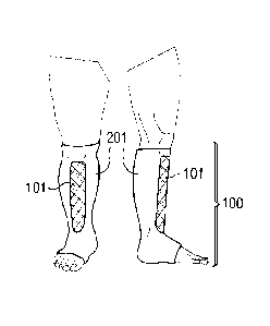
Referring to Figs. 1-4, the present disclosure shows a number of exemplary
liner
shapes100 and T100 disposed about a limb, in this case a leg of a patient.
These
Figures each show a front view and a right side view. Fig. 4 also shows a left
side
view of the liner shape 100. The liners in these examples are formed as
tubular
sleeves that may be donned about the limb, having an opening at both ends.
Other
liners are stocking-like having only a single opening and closed toe. These
liners
each include a first region (referred to as 101, 102, 103, 104) and a second
region
(referred to as 201) that differ in the amount of padding provided. In these
examples, the second region 201 comprises more padding than the first regions
101,
CA 02734299 2011-02-15
WO 2010/025186 PCT/US2009/055051
18
102,103,104. As shown in Figs. 1-4, the padded first regions 101, 102, 103,
104,
overlies prominent bony areas on the patient's limb. These liners (100 and
T100)
have a very low profile in the second region 201, having less padding, also
providing
high breathability.
The liner material may be any traditional material as known in the art, from
terry cloth
type material, to high performance techsheen with compression, to conventional
sock or compression stocking materials with flat-knit or circular or other
construction
with 8 ¨ 50mmHg compression, to product similar to Comperm brand tubing with
low
grade compression, or a stockingette material that comes in a roll, to a sock
type
construction. The padding that forms the first regions 101, 102, 103, 104 may
be
sewn in place in strategic locations to reduce skin surface pressures and
increase
comfort and decrease risk of pressure necrosis to underlying skin.
Alternatively, the
padding may be knitted or woven into place during liner construction, or
selectively
detachable.
The padded area of the first region may be attached to the liner material by
any of
many known techniques and may be selectively detachable, permanently attached,
or temporarily attached. Alternatively, the padding may be separate from the
liner.
Methods of attachment may include sewing, buttons, snaps, RF or ultrasonic
welding, gluing, laminating, or hook and loop type attachments, among others
as are
known in the art. Another method of attachment may be a pouch for the liner to
slide
into, or fabric glue to hold padding against liner. Alternatively, the padding
may be
knitted into place and contiguous with the liner material.
CA 02734299 2011-02-15
WO 2010/025186
PCT/US2009/055051
19
Fig. 1 details one embodiment of a liner shape 100 of the current disclosure.
The
prominence of the anterior tibial crest varies, but in some patients is sharp,
with little
overlying soft tissue. Attempts to place compression on the limb results in
pressure
necrosis and pain over the soft tissues over the anterior tibial crest.
Padding to this
area, as shown in the padded region 101 reduces skin surface pressure and
reduces
complications and increases comfort. The second region 201 details the liner
material in conjunction for use with the padded area.
Fig. 2 details another embodiment of a liner shape 100 of the disclosure,
where the
padded areas of the first region 102 provide protection to the anterior tibial
crest as
well as the anterior ankle area. The liner shape 100 details a knee high
embodiment
of the associated liner material 201, which could also represent a thigh high,
arm, or
other garment as known in the art. In the inventor's experience providing
therapeutic
compression to thousands of patients, the anterior ankle is the most common
location for pressure necrosis and pain under compression garments,
compression
bandages, and orthotics. This is due to the prominence in some patients of the
tibialis tendon, and the sharp bend in the leg at this anatomical location.
Fig. 3 shows another embodiment of a liner shape T100 of the current
disclosure,
where the padded areas of the first region 103 include the anterior tibial
crest, the
anterior ankle, as well as the malleoli and an associated liner material
forming the
second region 201, here shown as a thigh high garment T100, although other
embodiments, such as an arm, are possible.
Fig. 4 shows an embodiment of a liner shape100 where the liner shape 100
provides
padding in the first region 104 to all the highest risk areas in the lower
limb, including
CA 02734299 2011-02-15
WO 2010/025186 PCT/US2009/055051
the anterior tibial crest, anterior ankle, malleoli, and the first and fifth
metatarsals. As
with the prior embodiments, the second region 201 is less padded and may
include
only unpadded liner material.
Note that while the embodiment of liner shape 100 in Fig. 4 protects all the
highest
5 risk areas, it still covers very little surface area of the lower leg in
which liner material
201 covers much less than 50% and more likely 33% - 20% of the surface area of
the limb below the knee. Likewise, all the embodiments herein include a padded
first
region 104 that covers less than 50%, and more likely between 5%- 33% of the
surface area of the liner on the limb. This reduces material consumption
resulting in
10 cost efficiencies, and also provides a lower profile and higher
breathability to the
wearer, which translates into increased patient safety and comfort.
Fig. 5 shows a detail drawing cross-section of one embodiment of the liner
shape100
illustrated in Fig. 1. This cross-section shows liner material 300 that forms
the
second region 201 and one or more padding layers that cooperate to form the
first
15 region 101. The first region 101 padding layers here are shown as two
layers of
padding material 301 and 302. In this illustration, the two padding layers may
be
attached to the liner material 300 by any known means such as sewing, weaving
or
knitting them together at time of construction, RF or ultrasonic welding,
lamination.
The materials 301 and 302 may be beveled at the edges to allow smooth
transition
20 to the non-padded areas of the unpadded region 201. Furthermore, the
outer layer
(shown here as 302) may have less width to create a stair-step type beveling
of the
material. It is understood that more or less layers may be necessary,
depending on
the padding material chosen. Here, it is contemplated that any suitable
padding may
CA 02734299 2011-02-15
WO 2010/025186
PCT/US2009/055051
21
be used, including for example, spacer fabric, and thickness will depend on
application and compressibility of the materials.
Fig. 6 shows another exemplary cross-section of a liner shape 100, that may be
used as shown in any of Figs. 1-4. In this case, there is shown 2 padding
layers 303
and 304, with part of the padding missing in the layer 303. This is to reduce
skin
surface pressures over the anterior tibial crest. This groove may help hold
the
padding in the proper place, and also help distribute pressure more equally
over a
larger surface area by applying less padding over the middle of the anterior
tibial
crest and more on the sides, reduces the total pressure per unit area. This
reduction
in pressure per unit area may reduce risk of pressure necrosis and increase
comfort.
This may also improve breathability of the padding further.
Fig. 7 shows another embodiment of a liner shape100 that may be used as shown
in
any of Figs. 1-4. Here, the padding 305 forming first region 101,102,103,104
includes a wedge-shaped groove cut from the inside of the padding. The liner
material 300 forms second region 201 and may or may not follow the wedge. In
this
drawing, it does not come in contact with the groove.
Fig. 8 shows another embodiment of a liner shape100 that may be used as shown
in
any of Figs. 1-4, where two strips of padding 306, forming regions 101, 102,
103,
104, are used instead of one large one as in Fig. 7. Again, this embodiment
can
help reduce pressure to the anterior tibial crest area and redistribute to
either side.
Fig. 9 shows one exemplary embodiment of padding 307 that forms the padded
first
region in any of the liners discussed herein with application to the malleoli
(see Fig.
13) or metatarsal areas (Fig. 11). In this illustration, there is a hole 401
in the
CA 02734299 2011-02-15
WO 2010/025186 PCT/US2009/055051
22
padding 307. As shown in Fig. 10, this hole may go all the way through the
middle of
the padding 307, or shown as a cross-section 308 in Fig. 11 may be beveled.
The
padding may have beveling on the outer edges, which is not illustrated in this
drawing. Again, the reduced padding in the middle helps redistribute pressure
more
equally to a larger surface area and reduce pressure on the malleoli or
metatarsals.
Fig. 12 shows an exemplary embodiment of the padding 309 usable to form the
padded first region formed to accommodate curvature along a body part. In this
case, the padding 309 accommodates the anterior ankle (see Fig. 13). In Fig.
12
one or more slits or grooves 402 in padding 309 are cut or stamped into the
padding.
This groove or grooves 402 may extend only partway through the material, or
may
extend all the way through the material. These grooves 402 facilitate the
bending of
the padding and provide more even reduction of the skin surface pressures. The
grooves 402, or slits, would preferentially follow the outline of the
curvature of the
ankle, as shown in this illustration. Other embodiments are possible, such as
slits
that go vertically and follow better the course of the tibialis tendon. In
other
embodiments, holes can be used instead of grooves or slits. By changing the
number of holes, density of holes, and size of each hole, greater
breathability, better
conformity of the padding to the underlying skin curvature, and better
reduction of
skin surface pressure can be created. By modeling the pressure over a number
of
patients, one can engineer the best size and location of these grooves or
holes and
then use known methods of manufacture to place or create or mold the holes,
slits,
or grooves in the correct location of the padding in order to maximize
comfort,
breathability, conformability of the padded liner, and pressure reduction.
CA 02734299 2011-02-15
WO 2010/025186
PCT/US2009/055051
23
Fig. 13 and the Figures making up Figs. 14-19 each show the padded first
region of
the liner as located upon a limb, such as the foot. Although not discussed
further
with respect to these figures, each padded first region is associated with a
less
padded second region of a liner that covers at least a portion of the limb in
the
manner discussed above. These drawings however, are intended to show the
location of the padded first region relative to a patient's limb, such as a
foot.
Fig. 13 shows the padded first region 113 aligned such that the padding
provides
protection to the anterior ankle as well as the dorsal foot areas. In this
case, the
dorsal foot padding is often needed to facilitate edema reduction better under
the
overlying compression device rather than reducing skin surface pressures. The
padding, such as foam, may be shaped in such a way to provide maximum
therapeutic compression to the dorsal foot area.
Fig.14 shows a padded first region 114 disposed on the metatarsal areas as
discussed above with reference to Fig. 9. Fig. 15 shows a padded first region
115
disposed to provide padding to the anterior ankle and the dorsal foot. Fig. 16
shows
a padded first region arranged to provide padding to the malleoli as discussed
above. Fig. 16, shows that the padded first region 116 may be divided or
separated
into a plurality of separate padded regions.
Fig.17 shows an embodiment where the padding of the first region 117 provides
protection just to the anterior ankle and malleoli areas. Fig. 18 shows an
embodiment where the padding of the first region 118 provides protection to
the
anterior ankle and dorsal foot.
CA 02734299 2011-02-15
WO 2010/025186
PCT/US2009/055051
24
Fig. 19 shows an embodiment where the padding 119 provides protection to the
anterior ankle, dorsal foot, malleoli, and metatarsal areas.
Figs. 20 and 21 show liners with channeling which approximately follows the
lymphatic flow along the limb. Such compression garments are well known in the
art
and made of chipped or cut foam and sold under the name Med-Telesto, Solaris,
and Jovi. The garment may contain foam of different densities. Higher density
foam
is thought to provide more aggressive reduction of underlying lymphedema and
fibrotic areas from a process known as lipodermatosclerosis. In this
disclosure, the
author discloses a liner which has padding made of spacer fabric material.
This
material has quite an advantage over foam with lower weight and greater
breathability. The spacer fabric material may be cut into strips and sewn in
place, or
generated as a sheet or tubing or padding to specific areas as outlined in
Fig. 21. In
another embodiment, the spacer fabric is cut into squares or shredded in a
manner
similar to a foam shredder and used in the garment instead of foam. The use of
spacer fabric is possibly quite important, as it may make the garment more
breathable, dry quicker, less weight, lower profile, and decrease skin
moisture which
could therefore decrease risk of dermatitis and fungal infections and
cellulitis
compared to similar products using closed or open cell foam.
Figs. 22 to 24 show different liners employing the materials and arrangements
disclosed herein. Figs. 22 - Fig.24 show a liner shape 100 with a first padded
region
104, a second padded region 501, and a third unpadded or less padded region
601.
The third region 601 may comprise, for example, the liner material without
padding.
The first and second padded regions 104, 501 may be formed to have any of the
CA 02734299 2011-02-15
WO 2010/025186 PCT/US2009/055051
features discussed with respect to other embodiments. Here, the padded region
501
may include a different level of padding than the region 104, providing
different levels
of compression when used with a compression garment. Fig. 28 and 29 show a
second padded region 50 2 having the channels discussed above with reference
to
5 Figs. 20 and 21. Figs. 25-27 and 29 show a thigh-high liner with features
similar to
those discussed with reference to Figs. 22-24.
As discussed above, the padded regions of the liners may be formed by
incorporating a padding material formed of a spacer fabric therein.
Conventional
padding materials, typically comprising foam, gel, or other padding materials
provide
10 only limited breathability, sometimes resulting in heat rash dermatitis,
fungal
infection, itching, and overall patient discomfort. This can also result in
lack of
patient compliance when such liners are used and prescribed. In short, this
problem
with conventional materials can be detrimental to attempts at edema reduction
and
healing of wounds in edematous limbs.
15 However, exchanging conventional padding materials with spacer materials
eliminates many of the shortcoming of the conventional materials. As stated
above,
spacer material comprises a layered fabric material formed of at least two
layers of
materials separated by threads or filaments extending from one layer to the
other to
compressably maintain the spacing in a way that provides cushioning to loading
on
20 one of the layers. Because the spacer fabric has mostly air in-between
the two
layers, the material is highly breathable. Furthermore, the layers also may be
highly
breathable. This higher breathability means less incidence of heat rash
dermatitis
and less risk fungal infection. This reduction in the incidence of dermatitis,
itching,
CA 02734299 2011-02-15
WO 2010/025186 PCT/US2009/055051
26
and overall patient discomfort directly addresses issues contributing to lack
of
,
compliance with compression in patients. Accordingly, incorporating spacer
fabric as
a padding material would increase patient compliance, directly affecting and
improving the results of edema reduction and healing of wounds in edematous
limbs.
The spacer fabric padding may be used as sheeting cut to fit the area that
needs
padding, may be cut and sold in shapes (ankle pad, shin pad, mastectomy pad,
oval
shaped pad), and may be used over fibrotic and indurated areas to soften
tissue and
help reduce lipodermatosclerotic changes. Alternatively, the spacer fabric
padding
disclosed herein may be incorporated into a liner product. The spacer fabric
may be
woven with different monofilament densities of sizes even within a sheet, in
order to
provide softer padding to some areas and harder padding to other areas. Since
some spacer fabrics are woven on a circular knit machine, the machine may be
programmed to create padded liners directly with an automated or semiautomated
process, either with or without channeling. Such a product has significant
cost
advantages, and would likely weigh less than comparable foam liners and have
greater breathability.
Figs. 30 and 31 show an exemplary spacer fabric 502 usable as a part of the
liners
disclosed herein. Here, the fabric is sold as a sheet or roll. In this
embodiment, the
fabric includes linear grooves 71 which are cut or made during manufacturing.
These padded and grooved areas provide low and high areas of compression. Such
a spacer fabric has never been disclosed. The spacer fabric material has
inherent
qualities or higher breathability, lower weight, and increased comfort. By
varying the
length and size of the filaments extending between the two layers, different
densities
CA 02734299 2011-02-15
WO 2010/025186 PCT/US2009/055051
27
can be created. The grooves 71 and the padded areas 70 may vary in width and
height depending on the application. In some applications, a second layer of
spacer
fabric material or padding 503 also may be included.
Fig. 32 shows another embodiment of the liner padding as spacer fabric
material.
This time instead of channels the foam is made with taller areas of
compression 63
which are square or pyramid shaped with or without tapered sides. In use as a
part
of a liner with a compression garment, the taller areas are placed in contact
with the
patient's skin. Then under compression from the compression garment, the
taller
areas 63 move around under the garment against the skin and the movement is
thought to facilitate the breaking up of fibrotic areas of tissue and help
soften the
tissue over time. Fig. 33 shows another embodiment cross-section with sloped
sides
to the raised squares 64. It is understood that other embodiments and shaped
areas
are possible.
Figs.34 and 35 show a liner roll comprising a plurality of connected liners
manufactured to have both the padded region and the less padded regions built
in.
In some embodiments, the product may come in a large continuous roll such as
in
Fig. 34, which can be cut for each patient. In this embodiment, the padding of
the
first region 134 provides pressure relief to the anterior tibial crest and
anterior ankle
areas. This has use in wound care, physical therapy, and orthopedic offices to
provide protection under compression bandages, wraps, orthotics, and casts.
Such
an embodiment may be preferable for hospital and clinic setting to a single
liner, and
may be more cost effective.
CA 02734299 2011-02-15
WO 2010/025186
PCT/US2009/055051
28
In another embodiment as shown in Fig. 35, the padding 135 is wide enough that
it
provides relief to the anterior ankle, anterior tibial crest and dorsal foot
and comes in
a continuous roll. It is understood that it may have other uses too, such as
padding
for the inside or outside of an arm.
In some embodiments where the padding material chosen is foam, the density
chosen may reflect the application. It may be closed cell so it does not
retain
moisture easily, or open cell foam for wound care application or other reason.
The
foam may be reticulated for better breathability. If foam is used, it may be
laminated
on one side so that foam is not exposed. The foam may be on the inside or
outside
of the liner.
In some embodiments, the padding may contain multiple holes in it to improve
breathability. These holes may also affect the skin surface pressures under
the
device. The size and location of such holes may be changed to improve
breathability, skin surface pressures, and comfort with joint range of motion,
depending on the application. For instance, in one embodiment it may be
desirable
to use padding with high hole density or large holes over the anterior ankle
area for
better breathability, but still use thicker foam or spacer fabric material to
better
protect the tibialis tendon. It is understandable to one known in the art that
other
areas of high flexion such as the elbow and knee may desire more strategic
hole
placement or size to provide optimal padding, breathability, and
stretchability to the
affected area of the limb. The padding in some embodiments would have multiple
small holes poked in it to allow for breathing or with dye cut patterns
congruent at
edges, yet to allow motion at joints and/or to allow for breathing of the
liner.
CA 2734299 2017-05-26
29
The liner may be single use, a limited re-usable, or re-usable product with
long life
spar,.
In some embodiments the liner / padded areas would incorporate antimicrobial
materials/chemicals/products into liner material to reduce pathogen
colonization and
reduce risk of infection.
In some embodiments, there would be areas of the liner with padding to protect
bony
areas, and other areas with channeling to help direct lymph flow and
facilitate
oedema reduction.
Fig. 36 shows one example of a system for treating edema or other condition.
The
system comprises a compression garment 500 usable with the padded liner 100.
After the padded liner is donned and the first padded region is sufficiently
disposed
to protect the hard tissue areas of the patient in the desired manner, the
compression garment 500 is wrapped about the exterior portion of the liner to
provide compression therapy to the limb. The padding increases patient comfort
in
the hard tissue areas, while the lack of padding in the softer tissue areas
provides
breathability, is cooler, light-weight, and overall less bulky than a fully
padded liner.
In some embodiments, the compression garment 500 is a garment having bands
having short-stretch properties and may be any of the garments disclosed in
U.S.
Patent Application No. 10/975,590 filed October 28, 2004 and U.S. Patent
Application No. 11/733991 filed April 11, 2007
Using garments having the properties of short-stretch provides many benefits
to a
patient. A user can stretch the band and see and/or feel when the maximal
stretch
CA 02734299 2011-02-15
WO 2010/025186
PCT/US2009/055051
level is reached because the band may have a limited stretch range. Using
this, the
user can 'dial into' the correct level of compression when applying the
garment,
without needing to use a pressure sensor or an indices-type system to
determine the
correct compression level. This provides a very simple, but very reliable,
method of
5 reproducing the correct level of compression every time the garment is
donned.
Because the bands are applied at or near maximal stretch, it will not stretch
further.
Therefore, the garment provides maximal augmentation of the calf muscle pump
and
the more the leg tries to swell, the more the garment will work to prevent
swelling.
Thus, such a short-stretch garment has a high static stiffness index, which
has been
10 suggested to measure efficiency of the bandage / garment on the
augmentation of
the calf muscle pump.
The garment can be designed to be a single use disposable device, or can be
designed to be reusable. For severe venous ulcerations with lots of drainage
or
bioburden, the garment can be designed to be of disposable materials similar
to
15 those used in multilayer compression wraps. For mild draining
ulcerations, the
garment can be designed to be re-usable. In some embodiments, the garment can
be used to heal the ulceration, and then the user can continue using the
garment for
maintenance compression in order to prevent recurrence.
The garment can also be designed to provide graduated compression. For a
typical
20 30-40 mmHg compression stocking, for example, there can be 30-40 mmHg
compression at the ankle, but perhaps 20-30 mmHg at the calf level, 15-20 mmHg
in
the distal thigh, and 8-15 mmHg in the proximal thigh. Graduated compression
provides more compression distally on the limb than proximally, and
compensates
CA 02734299 2011-02-15
WO 2010/025186
PCT/US2009/055051
31
for gravity to provide optimum compression levels. Different embodiments of
the
garment can include one of the features listed below to provide a garment with
graduated compression. The features listed below can also be mixed and matched
to provide graduated compression by combining these various modalities in
combination to provide a sophisticated garment with various compression
levels.
Spacer Fabric as a Compression Garment
In some embodiments, the Spacer Fabric may be used to make not only a liner
for
use with a compression garment, but may be used to make a compression garment
itself. The spacing and filaments between the layers provides cushioning or
air
padding. Thus, in this embodiment, the garment itself is a padded compression
garment. In one embodiment, the Spacer Fabric would be generated to create a
short-stretch range of compression 15-90% maximum stretch with resting
compression at end stretch of 15-20mmHg, preferably with fairly abrupt end-
stretch
so that the user can feel when the band no longer stretches. The outer surface
of
the Spacer Fabric can be generated to have Velcro -type hook compatibility,
and
the opposing bands can be secured in place with standard hook material. This
garment would ideally have relatively abrupt end-stretch or bandage lock-out
so that
the user can readily identify when the garment is applied at maximum stretch.
This
embodiment may be excellent for postop surgical use and hospital use to
prevent
DVTs in patients, for example. Examples of compression garments that may be
formed with bands of spacer fabric are any of the garments disclosed in U.S.
Patent
Application No. 10/975,590 filed October 28, 2004 and U.S. Patent Application
No.
CA 02734299 2011-02-15
WO 2010/025186 PCT/US2009/055051
32
11/733991 filed April 11, 2007. Other embodiments may have 8-40mm compression
when applied at end-stretch to a limb portion.
In another embodiment, the spacer fabric would be laminated to a woven and /
or
knitted stretch or compression fabric or UBL (unbroken loop fabric) to provide
therapeutic compression levels. In one embodiment, the garment would consist
of
Spacer Fabric with UBL on the outside of the garment. In another embodiment,
there is a woven fabric which provides the end-stretch on the inner layer, a
spacer
fabric to provide padding, and an outer layer of UBL material. Other
embodiments
are possible, depending on materials and properties chosen. The compression
fabric could be knitted of Rochelle or Tricot or another knitted weave, or
could be a
woven fabric. The laminated fabric could provide the compression, the bandage
lockout or a combination of both, such that the combined layers provided
therapeutic
resting compression level of 8-50mmHg at or near end-stretch when applied to a
limb at rest, and a maximum elasticity of 15-90% maximum stretch with
preferred
range of 25-50% maximal stretch. Additionally, the laminated woven or knitted
fabric
could provide the Velcro -like hook compatible surface, as is known in the
art. The
fabric(s) could be located on the inside or the outside of the spacer fabric
or both.
The combined result would be correct compression level and built in padding to
prevent injury to the limb. Woven fabrics are especially valuable in designing
such a
system due to their ability to be designed with abrupt end-stretch.
In use, the system with a liner and a compression garment as disclosed herein
may
be used to treat a swelling condition such as edema. The liner is first
applied to the
limb to be treated. The liner may include the first and second regions
discussed
CA 02734299 2011-02-15
WO 2010/025186 PCT/US2009/055051
33
herein, with the first region having thicker padding than a second region. In
some
embodiments, the liner is completely formed, with the padded first and second
regions prior to being worn by the patient. Thus, the liner is applied while
in a
completely assembled state. Applying the liner may include pulling the tubular
liner
from the proximal end over the foot in the manner of donning a sock or may
include
forming the liner on the leg. The liner may be form-fitting about the limb and
may be
adjusted or aligned so that the padded first region overlies a bony area on
the limb
as desired. In some embodiments, the padded liner is shaped to overlie
specific
portions of the limb to provide the padding to the bony area. In some
examples, the
padded first region may be applied to overlie at least one of the anterior
tibial crest,
anterior ankle, malleoli, and the first and fifth metatarsals. In some
examples, the
liner may be applied so that the padded first region overlies a plurality of
any of the
regions discussed. In addition, applying the liner to the limb also includes
aligning
the less-padded second region over soft tissue on the limb. In some
embodiments,
the less padded second region is unpadded and comprises only a thin layer of
liner
material, permitting the liner to be lightweight, breathable, and comfortable.
In some
embodiments, the padded first region employs spacer fabric having first and
second
fabric-type layers held apart by filaments such that a layer of air lies
between the first
and second fabric-type layers.
Once the liner is properly applied with the first and second regions in place
as
desired, a compression garment may be donned over the liner on the limb. The
compression garment may comprise a series of connected bands wrappable about
the limb and connectable to each other to secure the garment on the limb. In
some
CA 02734299 2011-02-15
WO 2010/025186 PCT/US2009/055051
34
embodiments, the garment is formed to have properties of a short-stretch
material to
apply compression to the limb. The padding in the liner distributes
compression
loading about the bony areas in a manner that makes wearing the compression
garment and liner relatively comfortable for the patient. In some examples,
the
method of use also includes cutting the liner from a liner roll before the
liner is worn
by the patient.
Fig. 37 shows another embodiment of the padded liner. This embodiment shows
the
liner made incorporating padding for the entire limb, such as spacer fabric.
In this
embodiment, the spacer fabric is cut so that it can be wrapped around the
entire
lower limb. In the preferred embodiment, the outer portion of the garment is
Velcro -like hook compatible or has hook compatible portion 652, such that
attachment mechanism 651, made of Velcro -like hook material, may be used to
attach to the attachment mechanism 651 in an overlapping manner. The tongue
area 650 is designed to provide padding to the anterior ankle area and dorsal
foot.
While this padding design is bulkier than some other embodiments, the spacer
fabric
design is highly breathable and provides adequate padding to protect the
underlying
tissues. Such a garment may be desirable for very fragile skin or skin with
wounds
circumferentially, for example.
Although disclosed as being used over the foot and leg, it is also
contemplated that
the liner disclosed herein may also be used to treat the arm, shoulder, hand,
wrist,
knee or other portion of a limb on a patient or an animal. In addition to
being used
under a compression garment, it also may be used under an orthotic, cast, or
bandage. The padding of the second region may be located for example, to
provide
CA 02734299 2011-02-15
WO 2010/025186 PCT/US2009/055051
increased padding over the anterior tibial crest, the anterior ankle, over and
around
the medial and lateral malleoli, over the 1st metatarsal head medially and the
5th
metatarsal laterally, over the dorsal foot, and/or over the knee area for
example. It
also may be used to provide increased padding over the palmar hand, the dorsal
5 hand, the wrist area, and/or the elbow, for example. In some embodiments,
the
padding is spacer fabric while in other embodiments, the padding is chipped
and/or
channeled foam mixed with smooth foam over the aforementioned areas. The liner
may have therapeutic compression properties in the range of 8-50mmHg resting
compression.
Trim-To-Fit Compression Garment
Correct fitting of compression garments to limb shapes necessitates custom and
off-
the-shelf varieties. Foot length varies considerably, and there is variation
in width
and therefore circumference of feet, as well as considerably variability in
ankle and
calf circumferences and shapes, as well as height. The same applies for thigh
high
and arm and hand sizes. Most compression garment manufacturers, therefore, use
custom and off-the-shelf solutions to fit a wide range of patient sizes. The
custom
garments, however, take time to manufacture. It is not uncommon, for instance,
for
custom compression stockings to take one month or longer from date of order
until
the patient receives the garment. Furthermore, errors in manufacturing and
measurement sometimes necessitate remanufacturing the garment or altering the
garment in order to get a proper fit. This is very inconvenient for the
patient, who
CA 02734299 2011-02-15
WO 2010/025186
PCT/US2009/055051
36
needs therapeutic compression immediately, and must make-do with an off-the-
shelf
garment or bandage until the custom garment arrives and fits correctly.
Furthermore, in some patients you need compression over the distal forefoot,
at the
level of the metatarsal heads, in order to prevent lymphostatic pooling of
edema in
this area. In other cases, you want to avoid compression over the metatarsals
in
order to reduce chance of injury due to pressure directly over a bony surface.
The
ability to make these clinical decisions and take immediate steps to provide a
correctly sized and suitable garment is very important in order to provide
proper
therapeutic compression safely and effectively in a patient.
Lastly, patient limbs vary in geometry from conular to tubular to other odd-
shaped
morphologies. At present, when a band is wrapped horizontally about a limb
that is
conular, it is tighter around the wider, more proximal portion while being
looser
around the distal, more narrow portion. The net effect of this is to promote
the
likelihood of the band sliding down the limb, which becomes more problematic
on
more conular-shaped limbs.
What is needed, therefore, is a garment system that is customizable at point
of sale
to patients by a medical equipment company, clinic, hospital on site, or even
by the
patient themselves so that the garment is immediately available and correct
fit can
be established with on-site customization that is simple, reliable, and
predictable.
One way of customizing as described uses a trim-to-fit solution permitting
providers
and even patients to trim the garments to provide a proper size while also
providing
proper and desired compression levels.
CA 02734299 2011-02-15
WO 2010/025186 PCT/US2009/055051
37
For the trim-to fit solutions, the material would ideally be short-stretch
material or a
material having properties of short stretch, with maximum elasticity of 15-
100% such
that the garment provides a compression level that falls within the range of 8-
50mmHg, when applied on a resting supine limb at or near end-stretch. It is
understood however, that non-elastic or moderate-stretch or long-stretch
embodiments may be chosen. A variety of standard materials known in the art
for
treating swollen limbs may be used for this invention. It is understood that
the
appropriate choice and location of markings would take into account the
stretch of
the material in order to properly trim and fit the garment to the patient.
Additionally, for use over legs, thighs, and some arms that are more conular-
shaped,
it would be beneficial for a few of the bands to be trapezoidal or trapezoidal-
like in
nature, with both band ends wider on the distal side of each band such that as
the
band is wrapped around a conular-shaped limb the bottom edge of the band may
be
applied in a more horizontal plane. This will provide more even compression to
the
limb and will better resist sliding down the limb. For one preferred
embodiment, a 1
way stretch material may be preferred in order to maximizing working
compression
and minimize band narrowing as it is pulled. In order for the garment to fit
best,
however, it may be desirable for the material to stretch in the width of the
bands at
least 5-25%, depending on the angles of the trapezoidal or trapezoidal-like
shape. In
some embodiments with these trapezoidal shaped bands, the bands may have
horizontal shape proximally, but trapezoidal shaped distally with less width
to the
band in the middle than at the ends. For such a band, if it is pulled around a
conical
shaped limb portion, the result would be a more uniform distribution of
compression
CA 02734299 2011-02-15
WO 2010/025186 PCT/US2009/055051
38
and more upward pulling vector force, which would prevent garment slippage
over
time. One example of such a trapezoidal band is shown in Fig. 57a and an
example
of a garment using such bands, along with straight bands, is shown in Fig. 58.
Fig.
57b shows application of a rectangular shaped band on a conical shaped limb.
In
this case, the compression is largest at the top of the band and the bottom
portion of
the band has less compression, making it more prone to slip. As shown in Fig.
57b,
the band slips around the sides and the central portion tends to hold its
position
more. Fig. 57c shows a trapezoidal shaped band applied to the limb. Since the
band is pulled tighter at the base, it conforms better to a conical shaped
limb and is
less prone to slippage. Fig. 58 shows a garment where some of the bands are
trapezoidal shaped. In other embodiments, all or just one of the bands would
be
trapezoidal shaped.
Fig. 38 shows embodiments of such a garment for the lower limb. It is
understandable that a similar design can be used for thigh high or arm
garments as
well as other limbs or body parts of a person or animal. Fig. 38 shows one
preferred
embodiment of a footpiece. This footpiece 701 has lower portion 702 and ankle
portion 703. The lower portion 702 has markings showing appropriate places
where
the footpiece can be trimmed in order to properly fit a wider range of feet.
The
markings 702a ¨ 702c show where to cut the length of the footpiece. The lines
702d
¨ 702f show where to trim to adjust the width of the footpiece. The sides E
are sewn
together in the preferred embodiment and attached to the middle of the band
703.
The band 703 has markings 702g-702j which show where the band may be trimmed
in order to better fit the size of the foot. The band 703 is designed to be
trimmed on
CA 02734299 2011-02-15
WO 2010/025186 PCT/US2009/055051
39
both sides along the same marking, in order to fit symmetrically, but may be
trimmed
as needed to properly fit the limb portion. The band 703 is designed to be
applied
around the ankle and downward across the dorsum of the foot, but may be
applied
directly across the ankle if desired.
Similarly, the bottom of the footpiece 702 is designed to be trimmed on both
sides of
the markings 702d-702f in order to symmetrically fit the foot, but may be
trimmed
differently as desired in order to properly fit the limb portion. Attachment
methods as
are known in the art may be used to attach the pieces together, as is known in
the
art. In the case of the preferred embodiment, pieces 704 ¨ 706 may represent
the
attachment mechanism. In one preferred embodiment, the attachment mechanism
would be a piece of Velcro -like hook material. In other embodiments, the
attachment mechanism may be tape, material with fabric glue, button, metal
clasps,
holes for laces, or other mechanisms as are known in the art.
In this preferred embodiment, the garment would have an outer surface with
areas of
Velcro -like hook compatible loop material in order to fasten to the hook
material. In
this embodiment, the attachment mechanisms 704-706 are selectively detachable.
In other embodiments, the attachment mechanism may be manufactured
differently.
Figure 39 shows close up of another embodiment of the attachment mechanism. In
this embodiment, the attachment mechanism has an area of semi-permanent or
permanent mechanism 707a, such as industrial strength Velcro -like hook and
loop
or very strong adhesive. Once the garment was trimmed to fit the limb
correctly, the
attachment mechanism 707a would then be fastened to the end of the band. Once
attached, the area 707a would be difficult to remove. A second area of the
CA 02734299 2011-02-15
WO 2010/025186 PCT/US2009/055051
attachment mechanism 707b, is designed to be less permanent and easier to
remove. This way the garment could be removed periodically or daily at area
707b,
while area 707a stayed attached. In some embodiments, this would make the
garment easier to don and doff and provide a simpler and more reliable
solution,
5 which may be less confusing for the person donning and doffing the
garment. In
other embodiments, the garment may be single use and the attachment mechanisms
may be quite permanent, requiring cutting away of the garment or destroying
the
attachment mechanism upon removal. Such an embodiment may be preferable for a
single use or limited reusable embodiment of the garment, such as for wound
care,
10 clinic or hospital use.
For attachment mechanisms 704, it may be preferred to have the attachment
mechanism such as Velcro -like hook material on both sides. For the footpiece
attachment mechanisms 705 and 706, however, there may only need to be
attachment mechanism on one side. For example, once the garment was trimmed
15 along lines 702d on both sides, one side of the material would fold
under the other
side of the material to create a small amount of overlapping. This would be
necessary and desirable in most embodiments in order to prevent windowing
(area
where there is no compression over a limb portion). In this case, the
attachment
mechanism may only need to be on one side, such that the attachment mechanism
20 holds the sides together once applied over the limb portion.
There are additional benefits to the design of an attachment mechanism which
can
be placed on either the inside or outside portion of the limb. For instance,
the
attachment mechanism may be best applied on the inside or the outside portion
of a
CA 02734299 2011-02-15
WO 2010/025186 PCT/US2009/055051
41
foot. Since the attachment mechanism is removable, a single design can provide
right and left foot sizes and provide symmetry. This would reduce the number
of
garments needed to properly stock and fit a wide range of sizes, and provide
better
patient comfort and fit with more symmetrical appearance.
Fig. 40 shows one embodiment of a legpiece 801 of the present invention using
trim-
to-fit design. In this embodiment, one or more of the plurality of bands 802
have
markings 802a-802c which show where to trim the band in order to fit a smaller
size
limb. By determining limb size and where to trim each band, the garment can
fit a
wider range of patients. In addition, it can be used for active treatment
phase
edema reduction as the garment size may be reduced as the edema reduces
allowing the patient to be treated and released in the same garment creating
great
cost savings for both the patient and health system.
Since leg length varies considerably among patients, band 808 has attachment
mechanism 810 to attach to the upper or lower bands or an optional spine 811.
The
attachment mechanism 810 has sections 810a and 810b. Section 810a attaches to
the more proximal band 808 on either the inside or outside of the band. The
section
810a may extend the entire width of the band, creating a spine over this
single band.
Attachment mechanism 810b attaches to the inside or outside of band 807. The
attachment mechanisms may be of any method as known in the art, such as
permanently, semi-permanently, or selectively detachable. In one embodiment,
the
attachment mechanism 810a is sewn onto the band 808 and the attachment
mechanism 810b is sewn onto the spine 811. The user can then cut away the
upper
band 808 if desired by trimming the attachment mechanism 810 between sections
CA 02734299 2011-02-15
WO 2010/025186 PCT/US2009/055051
42
810a and 810b to shorten the garment. More than one attachment mechanisms 810
can be used, with one between each band. This allows the garment to be trimmed
to shorten it in an easy and reliable manner in order to better fit the
patient.
By creating each garment with the upper band(s) as separately attachable
and/or
trimmable, there is no reason to stock short, regular, or tall garments,
reducing
inventory and increasing the likelihood that the trim-to-fit garment can fit
any given
patient population. This is especially important for Durable Medical Equipment
companies, hospitals, and clinics, who would prefer to stock fewer sizes to
fit their
range of patients. By reducing inventory, cost savings are realized. By having
customizable features, the garment can better fit any given patient.
Attachment mechanism 812 is used to connect the ends of band 802. The
attachment mechanism 812 may start on the outside of the overlapping band on
either side. This is advantageous, as the trim-to-fit legpiece can therefore
be made
such that the attachment attaches to the inside or to the outside (medial or
lateral
side) of the legpiece, depending on patient ability and preference. In most
embodiments, the patient will want a Velcro -like attachment mechanism that is
utilized such that it is on the outside of the legpiece so the Velcro -like
attachment
mechanism does not rub against each other medially on the limb.
The attachment mechanism 812 may have sections 812a and 812b. One of the
sections may be permanent or detachable but with greater holding strength than
the
opposite end. For example, if section 812a of the attachment mechanism used
standard Velcro -like attachments, and section 812b used more industrial
strength
Velcro -like attachments, then section 812b would be designed to be applied to
the
CA 02734299 2011-02-15
WO 2010/025186 PCT/US2009/055051
43
end of the band. The user would then overlap the bands appropriately and use
section 812a during daily use to don and doff the garment, leaving section
812b
attached. Section 812b could be removed, however, for instances like washing
the
garment in a washing machine, where the Velcro -like hook and loop could
increase
wear or cause garment entanglement which would make garment less easy to clean
and use on daily basis.
One example of a preferred embodiment of the attachment mechanism uses HiTex
corporation HTH-833 as section 812b, and HitTex corporation trihook-150 BEI as
section 812a. Because HTH-833 is very aggressive hook material and very
difficult
to remove, it would be designed to stay attached to the end of band 802 long
term.
The patient would then remove and apply section 812a during daily use. The
entire
attachment mechanism 812 could be removed during weekly washing and on an as
needed basis, and the rest of the time the patient would wash the liner daily
with the
compression garment.
Another benefit of attachment mechanism 810, is that the degree of overlap of
one
band 802 relative to one or more other bands 802 is realized. In some
embodiments, there will be an attachment mechanism 810 between each band, such
that some bands may overlap completely, and other bands may overlap less. By
determining the compression of each band, and determining the desired
compression level to that limb portion, one could change the degree of overlap
over
certain portions of the limb to increase compression. For instance, most
compression garments have gradient compression with more compression at the
ankle and less compression proximally. By overlapping bands more distally near
the
CA 02734299 2011-02-15
WO 2010/025186 PCT/US2009/055051
44
ankle and less proximally near the knee area, one can create gradient
compression.
By applying the garment at end-stretch, you can create graduated end-stretch
compression if desired. Furthermore, by selecting bands with more compression
at
end-stretch or less compression at end-stretch, you can select more or less
compression to a limb area. Thus the trim-to-fit allows the user to be able to
customize compression levels to desired limb portions.
Figure 41 shows another embodiment of the current invention, which shows
multiple
attachment mechanisms 708. In this embodiment, the attachment mechanism is
already in place on the garment 702. In one embodiment, the attachment
mechanisms 708 represent pieces of Velcro -like materials that are permanently
or
semi-permanently attached using a method that is known in the art such as
sewing,
RF welding, gluing, or ultrasonically welding into place. The attachment
mechanism
is divided between the markings on the garment, in order to facilitate easier
trimming
of the garment to properly fit the underlying limb portion.
In another embodiment, attachment mechanism 708 may be one large piece with
the
markings on the attachment mechanism and mechanism of attachment as shown on
the band 702 in Fig. 41. Here, the garment can be safely cut to size as
desired
along the lines 702E or 702F even through the attachment mechanism, and still
work
properly and reliably.
The markings on any of the garments in Figs. 38-41 may be color coded, may
have
indicia, labels, or other identifying marks that help identify or determine
which line the
garment should be trimmed in order to provide the proper fit. In some
embodiments,
the markings are woven into the fabric, while in other embodiments, the
markings
CA 02734299 2011-02-15
WO 2010/025186 PCT/US2009/055051
are applied using an ink or dye. Furthermore, the markings may be permanent or
may wash or wipe off, such that after customization to fit, the markings may
be
removed. In some cases, a measurement form or table may be used to help guide
the determination and help trim the garment quickly and effectively without
error in
5 order to provide proper fit and no markings would be needed. Guide
patterns that
overlay the garment and identify the trim lines also may be used. Other
markings
are also contemplated.
Joint Piece
10 Fig. 42 shows an embodiment of a complete kneepiece 850 applied to a
knee joint
as seen from the front of the knee. Fig. 43 shows the kneepiece 850 lying
flat.
Components making up the kneepiece 850 of Fig. 42 are detailed in Figs. 43-46.
These include an hour-glass shaped middle band 852, an optional spine 854, and
two straight bands 856. Figs. 43 and 44 show the hourglass shaped middle band
15 852 with notches 858 cut out as seen at the top and bottom of the
hourglass shape.
The hourglass shape band 852 interposed between the optional spine 854 and the
straight bands 856 allows the kneepiece 850 to conform to the knee while
providing
good compression at the same time.
Padding 860 is added to the posterior of the kneepiece 850 as shown in Fig.
43.
20 This padding 860 helps protect the sensitive arteries, veins, and nerves
that course
along the posterior of the leg when the knee is bent, protecting these
structures from
an impinging garment during flexion. It also increases the central diameter of
the
kneepiece 850 and provides some rigidity to the design, both of which help
prevent
CA 02734299 2011-02-15
WO 2010/025186 PCT/US2009/055051
46
the kneepiece from wadding from both the bottom and top towards the center
after
repeated flexion and extensions of the knee. Because of the benefits it
provides, the
padding 860 can be an important component.
In some embodiments, the kneepiece is made with and without the proximal
straight
band 856a and the distal straight band 856b, leaving only the middleband 852,
the
optional spine 854, and the optional padding 860. In these embodiments, the
kneepiece could be directly attached to a separate thighpiece. Alternatively,
a
Velcro -like material strip (not shown) running horizontally along the
proximal or
upper lateral portion 862 and along the distal or lower lateral portion 864
could be
employed to hold the kneepiece in place on the thighpiece and legpiece
respectively,
rendering the kneepiece completely detachable. Fig. 47 is a back view of the
kneepiece 850 shown in Fig. 43.
This customizable design, and the option to use or not use the straight bands
586
with the middle band 852, allow for user preference in placement, allow the
user to
use the legpiece with or without both the kneepiece and thighpiece, and allow
the
kneepiece to be used by itself, such as for post op knee surgery. The design
allows
the kneepiece to be quickly and easily removed by the doctor for dressing
changes
and reapplied similarly. It could also be used for sport injuries. In
addition, in some
embodiments, the kneepiece employs channeled foam or spacer type fabric liners
and facilitates edema reduction. The channeled foam may be longitudinally
directed
to facilitate fluid removal, while providing padding for comfort and
protection to the
posterior knee area.
CA 02734299 2011-02-15
WO 2010/025186 PCT/US2009/055051
47
The Velcro -like hook materials could either be attached to the band ends or
made
detachable so that the kneepiece too could be a trim-to-fit device. In some
embodiments, the bands, including the spine are held together by fasteners,
such as
the hook and loop fasteners 866. These fasteners 866 can be used to connect
the
middle band 852 to the straight bands 856, and likewise, similar fasteners may
be
used to connect the padding to the middle band 852 or spine 854
Additionally, the bands and/or spine may be made from both one way stretch and
two way stretch. The two way stretch bands provide a softer end stretch over
more
sensitive areas such as joints, and allows for range of motion in addition to
compression when used over joints. Thus, two way stretch bands may be
preferable
for use over joint articulation areas, whereas one-way bands may be preferable
over
non-joint areas, as they are less prone to necking (shrinking in the middle
when
stretched).
Some embodiments, such as the kneepiece shown in Fig. 48, include a mesh
pocket
870 at the narrow portion of the hourglass middle band 564 which locates at
the
back of the knee when worn. This pocket 870 provides for insertion and removal
of
selected padding pieces 872, such as a foam insert, for better protection of
sensitive
parts of the back of the knee.
The pocket 870 and padding 872 may be selectively or permanently attached to a
central attachment mechanism 868 on the middle band 852. This central
mechanism may be a hook and loop fastener, for example, but also may be any
connection mechanism, including an adhesive, sewing, ultrasonic welding, and
CA 02734299 2011-02-15
WO 2010/025186 PCT/US2009/055051
48
others. In some embodiments, the pocket is permanently attached to the
kneepiece
850 and the foam may be removed fro the pocket for replacement or cleaning.
Figs. 49-52 show additional embodiments of kneepiece systems. Fig. 49 shows a
kneepiece 880 having three extending straps 882a-c. These straps connect to
each
other along a central spine 884. In some embodiments, the bands 882 and spine
884 are integral, and may be cut or stamped from the same material. In other
embodiments, the bands are attached to each other along lateral edges, thereby
forming the spine 884. In yet other embodiments, the garment is formed of a
single
piece. Their construction uses band materials similar to those used in figs.
42-45.
The oval and round portions are locations of stretch material to provide
greater
comfort for the kneecap area.
Fig. 50 shows another kneepiece referenced herein by the numeral 900. In this
embodiment, the kneepiece 900 is formed of a first material 902 and a second
material 904. These may be attached using methods known in the art. Here, the
first material is a long stretch material and the second material is a
different material,
such as a short stretch material. In use, the circle 906 fits over the kneecap
and the
band is then wrapped around the leg. Because of the U-shape, when the band is
wrapped around the leg, the U-shape portion straddles the kneecap and
connectors
908 hold the kneepiece in place.
Fig. 51 is another kneepiece referenced by the numeral 918. In this
embodiment,
the kneepiece comprises three bands 920a-920c placed adjacent each other. The
bands are connected along seam lines 922 extending substantially parallel to
lateral
CA 02734299 2011-02-15
WO 2010/025186 PCT/US2009/055051
49
edges of the bands. Connectors 924 are located at one or both ends of the
bands
and connect the band ends to the surface of the bands when wrapped around a
limb.
Fig. 52 shows how the kneepiece 918 of Fig. 51 is applied to the knee joint.
The padding used in the joint pieces may be selected from various foams, and
spacer fabrics, applied as one or a plurality of layers, and with profiles
that include
flat, channeled, grooved, with one or more holes, slotted, dimpled, raised, or
any
other profile as desired.
Trim-To-Fit Business Method
In another embodiment, a method and system are disclosed for providing custom
and or customized garments to patients from off ¨the-shelf or trim to fit
sizes /
components based on limb measurements. This is explained further with
reference
to Figs. 53-58.
Laplace's law dictates the correlation of leg circumference with compression
level.
For smaller limbs, there is more compression on a limb portion than for a
larger limb.
The width of the bands also is an important factor when determining the
compression level. For more narrow bands applied with the same tension, there
will
be more compression on the underlying limb portion than if the bands have
wider
widths. If the band is applied with the same tension to a limb portion with
wider
circumference, there is less tension per area on the underlying limb portion.
Therefore, to accurately gauge the compression applied to the limb at rest,
one must
take into account the limb circumferential measurements.
CA 2734299 2017-05-26
50 a
Fig. 55 shows an example of a form with instructions for custom fitting an off-
the
shelf garment. A user measures the actual circumference of an affected limb.
Instructions could include, for example, the following:
Legplecet
Measure circt rnterenee at point B, and Men measive 5 atictitimt
circumferences goirlp up he legi
by 5 cm increments. Maasure A-1:1 length following ihe posterior couleur ut
the leg. Fird
TTF lootpiece size U fleet which the measurements all. Details: Small TTF
legpleee berweon
35,5 cru and 38.5 crn length and leg circumference Lietnen 16 - 56 cm. It
length is between 36.5
arrd
44 cm. awly the enclosed extra hand to ate top al Me wrap, 11 length > 44 cm
Of
circumference > 58 oil, 8 large rrF legpiece wilt be requirml. Do col apply
LITE 11T logplece
on circumferences fess than 18 cm, ash may Dui og tirculation to very small
diameter limbs.
Starling tom the Olstal ms i band (Ootive) of the legpiece, cut exit
unstretcNed turid the samo
length as the corresponding circumference mcosuroment. You may round up to the
nearest 5 cm.
Footpiect
Measure mfool Crcumference. Measure distance X, Find the rr foctplece size
under which
the measurements all. Trim the correctly matched Tif foolpeice length and
midloot
dicumleimce to be the tirte as, a* retd rneasuzarryeats. Otherwise narK$s
custom
20
CA 2734299 2017-05-26
50 b
Then,
based on the type of material desired and the required compression level, a
Choice
Algorithm would help the user to select a correct product line. The Choice
Algorithm
graph, as shown in Fig. 53a indicates the proper resting compression of
different
band types (along the vertical axis) for a given limb circumference (along the
horizontal axis) when bands are supplied at end stretch. The compression
levels
would be different, depending upon the type of material chosen allowing for
choice
when prescribing the resting compression level. The band type rating includes
variations due to Laplace's law, which states that compression differs with
limb
circumference. In this example, these are short-stretch bands applied at or
near
end-stretch. In other embodiments, these may be other band types nonelastic,
long-
stretch, medium-stretch. One can use similar algorithms for maximal stretch
(100%
stretch), 75% maximal stretch, 50% maximal stretch for a given stretch
material, for
example, as illustrated in Fig. 53b. Other possibilities exist as well.
Instead of
displaying the subbandage pressure, the Choice Algorithm may display the Skin
Surface Pressure and take into account the type of padding used under the
wrap.
For example, a band applied over a thick foam liner with 1" of foam would
provide
less Skin Surface Pressure than a band applied over a very thin 2mm thick foam
liner. Thus, the user can use a simple chart to correctly select which padding
type
and band type to use for a given application or band level.
Fig. 53C shows another embodiment of a Choice Algorithm. In the United States,
most compression garments have a compression rating that lies in the ranges
of: 8-
CA 02734299 2011-02-15
WO 2010/025186
PCT/US2009/055051
51
15mm Hg, 15-20mm Hg, 20-30mm Hg, 30-40mm Hg, or 40-50mm Hg. Most
practitioners are used to prescribing a range of therapeutic compression, with
the
understanding that of-the-shelf garments provide this compression range over a
range of limb circumferences. The rating system typically has the most
compression
at the wrist or ankle, with less compression proximally so that graduated
compression is provided. Short-stretch products as illustrated in this
invention may
or may not provide graduated compression, as this may in certain cases be less
important for garments applied at or near end-stretch.
Fig. 53D illustrates a Color Indicia System for different ranges of
compression.
Since 15-20mm is generally safe except for severe peripheral arterial disease,
it was
given the color green. As the compression increases, the colors change to
reflect
more compression and therefore more caution. Red for instance, is often
associated
with stop lights, stop signs, or thermometer temperature level, as well as
blood, and
in this case represents higher intensity compression. The colormap shown in
53D
may be used in any of the Choice Algorithms or bands to indicate general
compression application. The colormap, for example, may be printed on the
bands
and reflect quickly the general compression level (safe to high intensity)
either alone
or in conjunction with other indicia. Other colormaps or ranges are possible,
for
instance using French or German Raul compression ranges, which are different
than
those commonly used in the United States. The colormap can be used in Fig. 55,
for
example. For the lower extremity garment pictured, additional color indicia
may be
added to show compression ranges. It is understood to one knowledgeable in the
art that there may be different colormaps even on the same band, depending on
the
CA 02734299 2011-02-15
WO 2010/025186
PCT/US2009/055051
52
circumference measurement. Such color indicia may provide safety factor as
well in
helping the person trimming quickly double check compression ranges (make sure
there are no red indicia if applying this to a patient with moderate /
advanced
peripheral arterial disease, for example).
For Fig. 53C, the color indicia may be used to provide color to the
rectangles, which
show the compression rating for certain circumferences. Since lower extremity
compression garments are generally rated by the least ankle circumference
compression rating, this chart shows the compression level ratings. Note that
in this
example, the same product can provide 20-30mm or 30-40mm compression,
depending on the circumferences to which the product is applied. By mixing the
band composition, band width, considering the circumference of the limb
portion at
that band level (in order to adjust for Laplace's law), as well as considering
band
overlap (in this case we mean how much each band overlaps on the preceding or
immediately following band level. For example, creating a garment with 50%
band
overlap would give effectively two bands overlapping along the entire garment
except at the ends and would give effectively twice the compression as if the
bands
did not overlap), many different combinations can be created to apply proper
therapeutic compression levels, yet the details of all these many complicated
variables remain hidden to the user, who gets a simple system to help them
safely
and reliably apply the correct compression level to the patient and correctly
select
the band materials or product and trim garment appropriately.
An indicia system can be drawn on, sewn in, or otherwise associated with the
band,
telling the user where to cut the band for a given circumference in order to
get the
CA 02734299 2011-02-15
WO 2010/025186 PCT/US2009/055051
53
correct band length for the desired compression. One example of this is to
create a
compressed scale. For example, a limb measuring 100cm in circumference may be
treated with a 50% maximal stretch short-stretch band. When applied at end-
stretch,
the garment would apply, for example, 30-40mmHg range resting compression over
a range of circumference limb portions. The band may contain an indicia system
with simple numbers, telling the user to cut the band there. Since the band
only
needs to be 100cm / 150% long to be applied at end-stretch, the indicia system
would tell the user to cut the band at a point slightly longer than the 66.67
measurement. Because of possible user error and prudence to leave room for the
garment to work even with some leg swelling, the corresponding indicia for a
100cm
limb at points would be put such that the user would cut the unstretched band
off at
75cm in length. This point would be 75/2 out from the middle of the band,
which is
37.5cm from the midpoint on either side. At this location on either side of
the band,
the indicia would say 100 or 100cm or something similar. There would be
similar
indicia for other limb measurements of 90cm, 110cm, etc. such that the user
would
know where to cut to make the garment the proper length to provide the desired
compression to a limb.
The method includes taking measurements of limb sections, then using an
algorithm
which takes into account the stretch characteristics of the material, to
figure out what
length to cut the band. The algorithm takes into account the maximum stretch
of the
material and tells the user what unstretched length to cut the band. This
measurement would be made outward from each of the spines or include a double
ruler which has middle as the zero point and counts up on either side. Also,
the
CA 02734299 2011-02-15
WO 2010/025186 PCT/US2009/055051
54
bands could in some embodiments be cut at the actual circumference measurement
of the limb for greatest intuitiveness.
Preferably a disposable or reusable ruler would be used which would tell the
user
where to cut each band. For different compression levels, there would be
different
algorithms. For example, one compression band may have maximum stretch of 50%.
The compression when applied at end stretch to one ankle size may be 40mmHg,
or
some other predetermined compression amount. The ruler would tell the user
where
to cut the bands so that when they are overlapped, the band applies a
compression
level of, for example, 40mmHg at or near maximal stretch. In another instance,
we
may want to use the same garment to only provide 20mm compression. In this
case,
the compression at half maximal stretch would be 25% stretch and may correlate
to
20mmHg. Another ruler or indicia would tell the user where to cut the band
such that
when overlapped on the limb the band applies a correct compression level of 20
mmHg.
To elaborate on this concept, we give the formula below which helps the
manufacturer develop a compression ruler or indicia system which takes into
account all the variables. This indicia system created may be printed on a
disposable paper double ruler included with the product or a reusable ruler,
or as
indicia printed on the band, to name just a few methods of relaying such
information.
In one example, compressed length markings are used on bands that consider the
amount of stretch and desire to leave some lateral overlap at each band level
(ex.
20-50% overlap after garment applied correctly). The user would measure the
actual
limb circumference and cut along the markings / indicia on the band(s) that
match
CA 02734299 2011-02-15
WO 2010/025186 PCT/US2009/055051
the measured circumference. The user may use an optional measurement guide
and instructions such as provided in Fig. 55 to assist with proper
measurements at
each band level. This could be a direct 1:1 relationship or some other
relationship.
For a 1:1 relationship, the user would measure the limb circumference, and
then cut
5 each band the same length as the circumference of the limb measured for
that limb
level. For a better fit, however, a formula could be used to create a
compressed
length at which each unstretched band should be cut. This compressed ratio
would
take into account the degree of stretch at application of the garment, and
perhaps
include a fudge factor in case of diurnal variation in swelling, mis-
measurements, etc.
10 One example of this compressed ratio would be as follows: The limb
measures
100cm in circumference at a level. The band is a short-stretch band with 50%
maximal stretch. The length of the band once applied at maximal stretch would
be
as follows:
BLn = ((LMa+PL) / (1+ BSA)) * (1+ PB0d)
15 Where BLn ¨ Band Length Needed for that limb level
LMa =actual Limb Measurement at that limb level
BSA = Percent band stretch at application
PBOd = Percent Band Overlap desired
PL = Padded Liner extra circumference at that limb level
20 For this application BLn = 100/1.5 = 66.67cm. The Percent Band Overlap
desired is
perhaps 20%, as we want to include extra length for possible measurement error
and leave room for the garment to still work if patient's limb swells 20% over
the
CA 02734299 2011-02-15
WO 2010/025186
PCT/US2009/055051
56
circumference measurement at the time of fitting / trimming. In this case the
patient
will be using a sock type liner under the wrap, so the PL will be negligible
and
estimated at zero. If there were a padded liner used on the limb, the PL would
add
the additional circumference of the padded liner to that limb portion to the
calculation. If the measurements of the limb LMa were done over a patient with
the
liner already applied, then PL would be zero for all calculations as the LMa
would
already include the extra circumference of the padded liner. In this case, the
compressed scale would have actual length of 66.67*1.2 or 80cm. So for this
compressed scale example, we would want the band at this band level cut to
have
80cm total unstretched length for proper fit.
The compressed indicia system can be done several different ways in order to
make
it easier to trim and fit the garment for the user. One way is to print a
compressed
scale indicia on the band. Another method is to use a double zero ruler which
the
person fitting would use to trim the band appropriately. This may be the end
user or
a medical professional, a hospital personnel, or a person at a Durable Medical
Equipment store. The compressed scale would tell the user to cut the band
length
80cm (40cm on either side of the midpoint) by using some type of indicia. In
this
example, the printed number may simply read "100" or "100cm" at band points
40cm
from either side of the band midpoint. By calculating and printing indicia at
regular
intervals (every 5-10cm for example using the compressed scale), the user
would
simply measure the limb at each band level and then cut at the location
closest to
their actual limb measurement. The built in scale will have done all the
calculations
CA 02734299 2011-02-15
WO 2010/025186 PCT/US2009/055051
57
in order to reduce risk of user error and make trimming as simple and
uncomplicated
as possible.
In other embodiments, the results of the compressed scale would be in a table
such
as shown in Fig. 55. In the case of the table of Fig. 55, for a band level
circumference in the range of 20-25cm, the user would cut the band length at
X1 for
Classic band type. If the measurements was 25.1 ¨ 30cm, the user would cut at
X2.
The table may reflect only one band composition such as a Classic brand band,
or
may include multiple types of product lines, such that the chart can be used
for any
product type. The table in Fig. 55, for example, shows where to cut for the
Classic,
Freedom, and Lite materials. This may be indicated if the different materials
have
different stretch levels.
In other embodiments, the chart illustrated in Fig. 55 may be different. For
example,
in some embodiments, it may tell the user exactly where to cut the bands to
achieve
100% maximal stretch for the first line of the chart X1-X11, 75% maximal
stretch for
the second line of the chart Y1-Y11, and 50% maximal stretch for the third
line of the
chart Z1-Z11. Since the band would be trimmed to exactly correct length, the
user
would apply the garment with exact specified compression, even if not applied
to
end-stretch. For example, if we want a user with moderate peripheral arterial
disease and diabetes with neuropathy to apply a Classic garment, we may use a
chart with indicia to trim the garment at 50% maximal stretch, in order to
provide 15-
20mm compression at the ankle. This would provide a safe therapeutic
compression
level for this patient, even though garment is not applied at end-stretch. For
a
different patient who has no peripheral arterial disease but has severe
lymphedema,
CA 02734299 2011-02-15
WO 2010/025186 PCT/US2009/055051
58
we may use a chart to trim the garment to fit at 100% maximal stretch to
provide
40mm end-stretch compression at the ankle and maximize the calf-muscle pump as
well as prevent any additional swelling, since the band is applied at end-
stretch.
Thus the chart provides another method of taking complicated variables and
summarizing them in a simple and reliable method to make a one-time change to
the
garment which will permanently change the fit and performance characteristics
of the
garment, depending on patient's limb sizes and desired performance
characteristics.
For another application, the chart may indicate where the user should trim the
bands
to provide a predetermined compression level (for example 30-40mm Hg range
compression). In this case, the chart would take into account the degree
stretch of
each band type in order to get the proper level therapeutic compression.
For a padded liner application, the compressed scale in some embodiments would
already consider the extra length needed for the band, depending on the
application.
For example, a padded liner as shown in Fig. 2 in one embodiment may increase
circumferential measurement of a limb portion such as the Least Ankle
Circumference by 4cm. Therefore for the following example PL = 4. In this
example,
we will use a short-stretch band with 34% maximal stretch and use the formula
to
properly size a band around a 27cm ankle. We will include just 5% overlap, so
POd
will be 0.05. In this case, the calculation becomes: BLn = ((27+4) /
(1+0.34))*(1+0.05) = (31/1.34) *1.05 = 24.29cm. Fora 73cm thigh measurement
with PL of 6cm and desired overlap of 10%, the calculation would be BLn =
((73+6)1
(1+0.34))(1+0.1) = (79/1.34)*1.1 = 64.85cm. Thus, by building in the desired
padding, the desired band overlap, and knowing the percentage stretch of a
short-
CA 02734299 2011-02-15
WO 2010/025186
PCT/US2009/055051
59
stretch band, a system can be built so the user can easily and with low error
correctly trim a garment to properly fit a limb portion.
Similar calculations can be used for any stretch material, such as the
trimmable
footpiece segments shown in Fig. 38. In this case, the indicia lines may be
marked
with the compressed scale in order to show the person trimming the garment how
to
trim it to properly fit the limb. Other indicia line types are possible for
footpiece
segments, and indicia may reflect something simpler for the user such as
trimming
along indicia which vary depending on shoe size or other type markings (small,
medium, large, for example).
For different types of materials, there may be different amounts of stretch.
Choice algorithm Fig. 53A shows a representative graph of different pressures
of
short-stretch bands applied to different circumference bands. All points are
for
bands applied at end-stretch. The user could look at the circumference of the
limb
portion and the desired compression level the healthcare practitioner wants to
apply,
and select the proper band type to use. In Fig. 53A, for instance, a 40cm
circumference ankle would have about 15mmHg resting compression for the LITE,
325mm for the Freedom, and 35mm for the Classic when applied at or near end
stretch. In one example, the patient has diabetes with moderate peripheral
neuropathy and some Peripheral Arterial Disease, but still needs lower
extremity
compression. In consideration of the patient's comorbidities the health care
practitioner may select to prescribe the Lite material for the patient. In
another
example, the patient has good blood flow and severe lymphedema with ankle
measurement of 40cm. In this case, the health care practitioner would want
heavier
CA 02734299 2011-02-15
WO 2010/025186 PCT/US2009/055051
compression and would select the Classic, with 35mm Hg resting compression on
the ankle area.
For selection of garments for use over the padded liner, the skin surface
pressure on
the limb will be different. The skin surface pressure we will define as the
pressure on
5 the outermost layer of skin. Therefore, the Choice algorithm would look
different
depending on the liner material and thickness and construction. These figures
could
in some embodiments give the correct Skin Surface Pressure, rather than the
SubBandage Pressure. In this case, the Choice Algorithm would have lower mmHg
reading built into the scale (giving correct skin surface pressures rather
than
10 subbandage pressures), to aid the practitioner with proper selection of
band
materials in order to provide proper therapeutic compression. It is important
to note
that the skin surface pressures measured also depend on tissue softness. This
means a posterior calf skin surface area would be lower due to softer
underlying
tissues than a reading over the anterior tibial crest, which is quite bony.
All these
15 considerations can be built into the correct scales to make a solution
that is as
simple and seamless as possible for clinician, technician, and patient.
Alternatively, the indicia showing where to cut may additionally or
alternatively
indicate the resting compression level applied to a specified circumference
when
applied at end stretch. Fig. 54, for example, shows bands with up to three
20 compression ratings XX¨YY¨ZZ where XX is resting compression level at
maximal band stretch, YY is resting compression level at 75% maximal stretch,
and
ZZ is the resting compression level at 50% maximal stretch. These ranges were
chosen in particular because users can determine not only the maximal end-
stretch
CA 02734299 2011-02-15
WO 2010/025186 PCT/US2009/055051
61
of short-stretch materials, but some general range of maximal stretch as well
with
reasonable predictability and reliability. By selecting the correct size and
trimming
correctly, the proper compression level for a given circumference can be
determined
by the user. These indicia may contain additional colormaps or use colormap
blocks
instead of numbers in order to indicate ranges of compression. One benefit of
such
a system is that this needs to be determined only once at time of garment
selection
and trimming, then the garment can be given to the patient and the patient can
reliably and predictably apply the garment with correct and safe compression
levels
and have a properly fit garment. In this example the band cut along the 30cm
line
(which could represent actual measurement or a compressed measurement as
described by equations above), the user would get resting compression of XX1
mmHg compression if the band was applied at maximal stretch. If applied at 75%
maximal stretch, for a 30cm band the user would get a resting compression of
YY1
mmHg. If the user applied the garment at 50% maximal stretch for a 30cm band,
the
user would get a resting compression of ZZ1 mmHg. Thus, the current invention
proposes a correct rating system of compression to determine actual subbandage
pressure or skin surface pressure of a garment. The compression rating system
could similarly include different ratings depending on the padding selected or
other
criteria.
Such a system has clinical benefits. For example, as lymphedema patient wears
a
Classic garment that provides 40mm resting compression to the ankle at a given
diameter 35cm in circumference. The patient is to undergo surgery elsewhere on
the body. Because surgery often involves fluid fluctuations due to IV fluids,
blood
CA 02734299 2011-02-15
WO 2010/025186 PCT/US2009/055051
62
loss, blood pressure fluctuations due to analgesia, etc, some patients get
significant
worsening of their lymphedema. At the same time, it is the author's experience
that
greater than 20mmHg for a surgical patient may be dangerous because of
anesthesia causing lower blood pressure and perfusion pressure, analgesias on
board etc. At the same time, lower extremity compression is necessary and
useful to
lower incidence of deep venous thrombosis. Therefore, by utilizing the rating
system, the correct compression for maximal therapeutic purposes and maximal
safety may be 20mmHg end-stretch. In this example, the patient may look at
their
garment and note that at 35cm their compression rating is 40-30-20. In this
case,
the patient understands they can apply their garment at 50% maximal stretch
and
get 20mm compression to their limb, even thought it is not applied at end-
stretch. In
this case, their garment with 20mm compression would certainly be safer than
wearing no garment at all (which would increase risk of blood stasis and DVT
formation), and safer than wearing a 40mm garment during surgery.
In other embodiments, the indicia may be linked to the amount of internal
compression applied to the tissues inside the limb portion, which is different
from the
surface compression applied by the garment either with or without a padded
liner.
Thus both the practitioner and/or end user would know both the external
compression generated as well as the internal compression to the limb as both
could
be printed on the indicia.
It is important to consider hand strength necessary to pull bands to
appropriate tension. Most doors are rated to open with pulling strength less
than 5
lbf of force. It is desirable, therefore, that the bands be configured such
that the
CA 02734299 2011-02-15
WO 2010/025186 PCT/US2009/055051
63
tension needed to pull the bands to near or at end-stretch be lie inside of a
range of
1 to 10 lbf. In some preferred embodiments, the desired tension lies within a
more
narrow range of 3-5 lbf. The amount of tension to achieve the compression
could be
varied by narrowing the bands or providing more overlap on the bands in order
to
keep required hand tension within an acceptable range, while providing a
garment
with the correct amount of therapeutic compression to the underlying limb.
Lower
required pull forces are preferable so that patients with less hand strength
can still
apply the garment correctly and with reliable and predictable compression
levels.
For far more elastic (beyond 100% stretchability) bands, geographic markings
(rectangle-square or oval-circle) may be used with appropriate stretch and
then trim-
to-fit markings. Squares may be placed on the device at the proper stretch
ratio that
would generate the requisite compression on the circumference that the garment
is
trimmed for. For short-stretch bands, these indicia may provide additional
confirmation the garment was applied correctly for best fit and function.
Any embodiment presented above with ruler, chart, or print-out on the band may
be
used. Also, a built in 20-50% compressed ruler may be used for the customer to
cut
bands such that there would be a fudge factor built in to allow for some user
error,
swelling fluctuation, etc.
Fig. 56 shows a relationship for at least partially determining a pressure
applied to a
limb at a given cross-section based upon the cross sectional area of the
liner. This
may be used for either a compression liner to be used beneath a garment or the
garment itself. Fig. 56 shows a leg, about which a liner is applied. A cross
section of
the liner is shown at three locations along the limb at A, B, and C. Each
cross-
CA 02734299 2011-02-15
WO 2010/025186
PCT/US2009/055051
64
section of the liner has an outer circumference and an inner circumference.
The
inner circumference is equal to the circumference of the limb.
The compression at each cross-sectional location is based upon the difference
in
circumference, divided by the inner circumference. Using this relationship,
compression can be calculated even when the thickness of the padding used in
the
garment differs from cross-section to cross-section.
Determining a pressure exerted on the limb at the cross-section may be
accomplished using a first function of the ratio described above (that is,
taking the
difference in circumference, divided by the inner circumference) and using a
second
function of the inside circumference at the same cross-section. For
explanation, the
following equations are provided and can be understood with reference to Fig
56.
For equal padding:
C" - C' B" - B'
_______________________________ < ______ and
C' B'
A" - A' B" -B'
_______________________________ < ______ .
A' B'
However, if less padding necessary at the areas having more bony tissue, then
depending on the amount of padding:
B" - B'
_______________________________ > ______ and
A' B'
_______________________________ > ______ .
C' B'
A" - A' B" - B'
_______________________________ < ______ .
A' B'
CA 02734299 2011-02-15
WO 2010/025186 PCT/US2009/055051
In simple terms, using a Laplace equation that shows a pressure P is
proportional to
the applied tension T and is inversely proportional to the circumference C,
and with a
constant K of proportionality, the following can be written:
P = KT/C
5 If two circumferences are given, an outer circumference C1 and an inner
circumference C2, with C1 being the larger circumference, the difference in
pressure
at C1 as compared at C2 can be expressed as:
P1 ¨ P2 = KT/C1 ¨ KT/C2
Since pressure P1 is at the larger outer circumference, C1, It will be
indicated by
10 Ppad, for pressure at the padding. Likewise, pressure P2 is at the
smaller inner, or
limb circumference, C2, so It will be called Plimb.
Thus:
Ppad ¨ Plimb = KT/C1 ¨ KT/C2
Now if only circumferences C1 and C2 are taken into account, they can be
related to
15 the difference in pressure Ppad ¨ Plimb with the normalized factor,
(C1 ¨ C2)/C2
as follows:
repeating equation 3)
Ppad ¨ Plimb = KT/C1 ¨ KT/C2
20 and using the normalized factor (C1 ¨ C2)/C2 with Ppad, or KT/C1, it can
be written:
Ppad ¨ Plimb = { KT/C1 } x { (C1 ¨ C2)/C2 }
By multiplying the numerators and the denominators at the right of the
equality, it can
be written:
CA 02734299 2011-02-15
WO 2010/025186 PCT/US2009/055051
66
Ppad ¨ Plimb = { KT(C1-C2)} / {C1 C2}
Algebraic manipulation gives:
Ppad ¨ Plimb = KTC1/C1C2 ¨ KTC2/C1C2
And then:
Ppad ¨ Plimb = KT/C2 ¨ KT/C1
Note that this derivation reproduced equation 3) with one striking difference,
the sign
on the right hand of the equality is reversed. To correct the right hand side
of the
equality it can be written:
(Ppad ¨ Plimb) x (-1) = KT/C1 ¨ KT/C2
The minus 1 indicates a pressure drop when going from the smaller
circumference to
the larger circumference.
It is important to note that the pressure at C1, or Ppad, is the pressure
exerted on
the padding, not on the limb. The limb experiences a pressure that is even
lower
than Ppad. The simplest example to illustrate this is with a fluid padding
(air or
liquid).
C1/7"-(Th
CA 02734299 2011-02-15
WO 2010/025186 PCT/US2009/055051
67
According to the laws of hydrostatics, the pressure in the fluid padding must
be equal
at all points, otherwise it would not be static. Since the pressure is
everywhere
equal, the force per unit area is also everywhere equal. However, the area at
the
limb surface, at C2, under the padding is smaller than the area at C1 the sub-
bandage area. Thus, the smaller area at the limb has less total force exerted
on it
than at the larger area at C1. A reverse analog to this (the principles being
exactly
the same) is a hydraulic braking system in a car. A small force exerted by the
foot
on a small diameter piston results in a large force exerted on a relatively
larger
piston which presses the brake discs to the rotor.
Business Method for Padded Liner
By using a form, the end user or business or clinical person can fill out the
form to
select the correct area(s) to be padded and the correct height of padding. The
user
can further select the correct thickness or layers of padding. This form may
then be
submitted to a manufacturer for custom manufacturing of the desired liner.
In some aspects, the present disclosure is directed to a liner for decreasing
subbandage pressure to bony areas of a patient's limb during treatment with a
compression garment while maintaining a lower profile in less bony areas, the
liner
comprising a tubular body portion having a proximal opening for receiving a
limb and
being sized to extend about the circumference of the limb, the body portion
including
a first region having relatively less padding and a second region having
relatively
more padding, the second region being located on the tubular body portion to
align
with relatively harder tissue areas of the limb, the first region being
located on the
CA 02734299 2011-02-15
WO 2010/025186 PCT/US2009/055051
68
tubular body to align at least in part with relatively softer tissue areas of
the limb,
wherein the second region comprises a padding material formed of spacer
fabric, the
spacer fabric having first and second substantially parallel layers separated
by
threads that provide compression resistance and that permit air between the
layers
and breathability of the limb.
In different exemplary aspects: The padding may beveled at edges providing a
transition in thickness from the second region to the first region. The body
portion
may comprise a pocket and the second region may be formed of a selectively
removable pad insertable into the pocket. The second region may comprise a
plurality of regions having different padding thicknesses. The tibia includes
0.2cm
padding and the anterior ankle portion includes 0.8cm padding. The padding in
the
second region is about .1-.2cm thick. The second region comprises a padded
material permanently fixed to the tubular body portion. The liner has a length
sufficient to extend from a patient's foot to a patient's thigh. The second
region
covers the first and fifth metatarsals. The second region is formed of a
laminate of a
plurality of padding pieces. The second region comprises a narrow spacing
between
adjacent padding pieces, the narrow spacing being disposed on the liner to
overlie
the anterior tibial crest and to distribute compression loading to the either
side. The
second region covers the anterior ankle and comprises a plurality of slits or
grooves
extending laterally across a central portion of the second region. The second
region
comprises a plurality of channels formed as indentations in the second region.
The
second region is arranged in the body portion to cover an anterior ankle
region, a
malleoli region, and a tibia region of the limb.
CA 02734299 2011-02-15
WO 2010/025186 PCT/US2009/055051
69
In some aspects, the present disclosure is directed to a low profile liner for
providing
increased comfort to a patient's limb during treatment with a compression
garment
by distributing subbandage pressure at bony areas of the limb. The liner
comprises
a tubular body portion having a proximal opening for receiving a limb and
being sized
to extend about the circumference of the limb, the body portion including a
first
region having relatively less padding and a second region having relatively
more
padding, the second region being located on the tubular body portion to align
with
relatively harder tissue areas of the limb, the first region being located on
the tubular
body to align with relatively softer tissue areas of the limb, the tubular
body portion
having a beveled edge portion transitioning from the second region to the
first region.
In some aspects, the present disclosure is directed to a system for applying
therapeutic pressure to a patient's limb. The system comprises: a liner
comprising a
tubular body portion having a proximal opening for receiving a limb and being
sized
to extend about the circumference of the limb, the body portion including a
first
region having relatively less padding and a second region having relatively
more
padding, the second region being located on the tubular body portion to align
with
relatively harder tissue areas of the limb, the first region being located on
the tubular
body to align with relatively softer tissue areas of the limb. The system also
comprises a compression garment having a plurality of stretchable bands
wrappable
about an exterior of the liner, the stretchable bands being adjustable to
provide a
therapeutic level of compression to the limb, the compression liner being
adjacent to
and providing compression to both the first and second regions of the liner.
CA 02734299 2011-02-15
WO 2010/025186 PCT/US2009/055051
In some aspects, the present disclosure is directed to a method of treating a
condition of a patient's limb. It comprises: applying a liner to the limb, the
liner
comprising a tubular body portion having a proximal opening for receiving a
limb and
being sized to extend about the circumference of the limb, the body portion
including
5 a first region having relatively less padding and a second region having
relatively
more padding, the second region being located on the tubular body portion to
align
with relatively harder tissue areas of the limb, the first region being
located on the
tubular body to align with relatively softer tissue areas of the limb. The
method also
comprises aligning the second region of the liner to overlie the relatively
harder
10 tissue on the limb and applying a compression garment about the liner to
apply a
therapeutic range of compression to the limb.
The present disclosure is directed to a therapeutic compression apparatus
comprising a liner having a tubular body portion with a proximal opening for
receiving
a limb of a patient; said tubular body portion having an inside region with an
inside
15 circumference that is sized to extend about and in contact with the
limb, the inside
circumference being substantially identical to a circumference of the limb at
a
respective area of contact; the tubular body portion having an outside region,
the
outside region having an outside circumference that varies from the inside
circumference at respective cross-sections through the tubular body, such that
a first
20 function of a ratio of the difference between the inside circumference
and the outside
circumference at a respective cross-section through the tubular body, divided
by the
inside circumference at said respective cross-section, and a second function
of the
inside circumference at said respective cross-section determines, in part, a
pressure
CA 02734299 2011-02-15
WO 2010/025186
PCT/US2009/055051
71
exerted on the limb at said cross-section when compression is applied by said
therapeutic compression apparatus.
In one aspect, the tubular body portion of the liner further comprises an
outside
cross-sectional area circumscribed by said outside circumference; an inside
cross-
sectional area circumscribed by said inside circumference; a padding area
being the
difference between said outside cross-sectional area and said inside cross-
sectional
area; a first region having a first integrated plurality of padding areas; a
second
region having a second integrated plurality of padding areas; the first and
second
region each having padding characterized by dimensions, properties and
profiles;
the padding in the first region has a dimension that is relatively thicker
than the
padding in the second region, and the padding in the second region has a
dimension
that relatively thinner than the padding in the first region; the first region
being
located on the tubular body portion to align over relatively bony and
tendinous areas
of the limb; and the second region being located on the tubular body portion
to align
at least in part with relatively softer tissue areas of the limb.
In one aspect, the padding is taken from the group consisting essentially of
spacer
fabrics, open-cell foams, closed-cell foams, viscoelastic foams, fluid filled
elastic
enclosed paddings, silicons, terry cloths, wadded fabrics, flexible aerogel
blankets,
gases, injected single or multipart foams, downs, metal and non-metal springs,
inorganic polymers, Newtonian and non-Newtonian fluids, dilatant fluids,
synthetic
and natural rubbers, and magnetic repulsion paddings.
In one aspect, the liner further comprises at least one opening in the first
region for
accepting insertable and replaceable padding.
CA 02734299 2011-02-15
WO 2010/025186
PCT/US2009/055051
72
In one aspect, the liner further comprises at least one attachment mechanism
for
replaceably attaching padding.
In one aspect, the liner further comprises at least one attachment for
permanently
fixing padding.
In one aspect, the liner further comprises padding having a thickness that
transitions
from a thicker padding in the first region to a thinner padding in the second
region.
In one aspect, the liner further comprises padding having a transition from a
padding
in the first region to no padding in the second region.
In one aspect, the liner further comprises padding having a thickness ranging
from
0.1 to 2.0 centimeters thick.
In one aspect, the liner further comprises a first region that covers the
first and fifth
metatarsals.
In one aspect, the liner further comprises a first region that is formed of a
laminate of
a plurality of padding pieces.
In one aspect, the liner further comprises a first region having narrow
spacing
between adjacent padding pieces, the narrow spacing being disposed on the
liner to
overlie the anterior tibial crest and to distribute compression loading to
either side.
In one aspect, the liner further comprises a first region that covers the
anterior ankle
and comprises a plurality of slits, grooves, and holes extending laterally
across a
central portion of the first region.
In one aspect, the liner further comprises a first region with a plurality of
channels
formed as indentations in the first region.
CA 02734299 2011-02-15
WO 2010/025186
PCT/US2009/055051
73
In one aspect, the liner further comprises a first region arranged in the
tubular body
portion to cover an anterior ankle region, a malleoli region, and a tibia
region of the
limb.
In one aspect, further comprising padding that includes channeled spacer
fabric.
In one aspect, further comprising padding that includes waffled and grooved
spacer
fabric.
In one aspect, further comprising foam padding having chipped, chunked and
channeled profiles in the same apparatus.
In one aspect, further comprising padding having profiles that include slots,
holes,
channels, linear grooves, non-linear grooves, cross-hatched grooves, dimples,
arrays of dimples, raised areas, arrays of raised areas, and combinations of
profiles.
In one aspect, further comprising a plurality of bands wrappable about an
exterior of
the liner and attachable to each other, the bands being adjustable to provide
a
therapeutic level of compression to the limb, the therapeutic compression
apparatus
being adjacent to and providing compression to both the first and second
regions of
the liner.
In one aspect, further comprising a plurality of markings on said plurality of
bands
that indicate proper locations for trimming the bands to accommodate different
limb
sizes, said proper locations being determined by the first function, the
second
function and other parameters to provide proper therapeutic levels of
compression to
the limb.
CA 02734299 2011-02-15
WO 2010/025186
PCT/US2009/055051
74
In one aspect, further comprising bands made from spacer fabric that provide
20mm
Hg compression to the limb when the bands are applied at end-stretch.
In one aspect, providing therapeutic compression to the limb further
comprising one
or more electrical conductive pads in contact with the limb, the conductive
pads
transmitting electrical pulses from a controller to motor nerves that
stimulate
contraction of muscles in the compressed limb, the therapeutic compression
apparatus thereby providing increased pumping of venous blood through the
limb.
In one aspect, the liner further comprises a length sufficient to extend from
a
patient's foot to a patient's thigh.
The present disclosure is directed to a method for applying therapeutic
compression
to a limb comprising inserting the limb into a liner having a tubular body
portion with
a proximal opening for receiving the limb of a patient; said tubular body
portion
having an inside region with an inside circumference that is sized to extend
about
and in contact with the limb, the inside circumference being substantially
identical to
a circumference of the limb at a respective area of contact; the tubular body
portion
having an outside region, the outside region having an outside circumference
that
varies from the inside circumference at respective cross-sections through the
tubular
body; calculating a first function using a ratio of the difference between the
inside
circumference and the outside circumference at a respective cross-section
through
the tubular body, divided by the inside circumference at said respective cross-
section; calculating a second function using the inside circumference at said
respective cross-section; and determining, in part, a pressure exerted on the
limb at
CA 02734299 2011-02-15
WO 2010/025186
PCT/US2009/055051
said cross-section when compression is applied by a therapeutic compression
garment.
In one aspect, the method further comprising determining an outside cross-
sectional
area circumscribed by said outside circumference; determining an inside cross-
5 sectional area circumscribed by said inside circumference; determining a
padding
area, said padding area being the difference between said outside cross-
sectional
area and said inside cross-sectional area; determining a first region having a
first
integrated plurality of padding areas; determining a second region having a
second
integrated plurality of padding areas; the first and second regions each
having
10 padding characterized by dimensions, properties and profiles; the
padding in the first
region has a dimension that is relatively thicker than the padding in the
second
region, and the padding in the second region has a dimension that is
relatively
thinner than the padding in the first region; locating the first region on the
tubular
body portion to align over relatively bony and tendinous areas of the limb;
and
15 locating the second region on the tubular body portion to align at least
in part with
relatively softer tissue areas of the limb.
In one aspect, the method of the padding is taken from the group consisting
essentially of spacer fabrics, open-cell foams, closed-cell foams,
viscoelastic foams,
fluid filled elastic enclosed paddings, silicons, terry cloths, wadded
fabrics, flexible
20 aerogel blankets, gases, injected single or multipart foams, downs,
metal and non-
metal springs, inorganic polymers, Newtonian and non-Newtonian fluids,
dilatant
fluids, synthetic and natural rubbers, and magnetic repulsion paddings.
CA 02734299 2011-02-15
WO 2010/025186
PCT/US2009/055051
76
In one aspect, the method of further comprising inserting and replacing
padding in at
least one opening in the first region of the liner.
In one aspect, the method of further comprising attaching padding to the liner
with at
least one attachment mechanism for replaceably attaching padding.
In one aspect, the method of further comprising permanently fixing padding to
the
liner with at least one attachment.
In one aspect, the method of further comprising transitioning the padding from
a
thicker padding in the first region to a thinner padding in the second region
of the
liner.
In one aspect, the method of further comprising transitioning the padding from
a
padding in the first region to no padding in the second region of the liner.
In one aspect, the method of further comprising using padding having a
thickness
ranging from 0.1 to 2.0 centimeters thick on the liner.
In one aspect, the method of further comprising covering the first and fifth
metatarsals with the first region of the liner.
In one aspect, the method of further comprising forming a laminate of a
plurality of
padding pieces for the first region of the liner.
In one aspect, the method of further comprising overlying the anterior tibial
crest with
padding having narrow spacing between adjacent padding pieces disposed on the
liner at the first region, to distribute compression loading to either side.
CA 02734299 2011-02-15
WO 2010/025186
PCT/US2009/055051
77
In one aspect, the method of further comprising covering the anterior ankle
with a
first region of the liner that comprises a plurality of slits, grooves, and
holes
extending laterally across a central portion of the first region.
In one aspect, the method of further comprising forming a plurality of
channels as
indentations in the first region of the liner.
In one aspect, the method of further comprising covering an anterior ankle
region, a
malleoli region, and a tibia region of the limb with a first region arranged
in the
tubular body portion the liner.
In one aspect, the method of further comprising using padding that includes
channeled spacer fabric.
In one aspect, the method of further comprising using padding that includes
waffled
and grooved spacer fabric.
In one aspect, the method of further comprising using foam padding having
chipped,
chunked and channeled profiles in the same garment.
In one aspect, the method of further comprising using padding having profiles
that
include slots, holes, channels, linear grooves, non-linear grooves, cross-
hatched
grooves, dimples, arrays of dimples, raised areas, arrays of raised areas, and
combinations of profiles.
In one aspect, the method of further comprising using a plurality of bands
wrappable
about an exterior of the liner and attachable to each other, the bands being
adjustable to provide a therapeutic level of compression to the limb, the
therapeutic
CA 02734299 2011-02-15
WO 2010/025186 PCT/US2009/055051
78
compression apparatus being adjacent to and providing compression to both the
first
and second regions of the liner.
In one aspect, the apparatus of further comprising generating a plurality of
markings
on said plurality of bands that indicate proper locations for trimming the
bands to
accommodate different limb sizes, said proper locations being determined by
the first
function, the second function and other parameters to provide proper
therapeutic
levels of compression to the limb.
In one aspect, the method of further comprising using bands made from spacer
fabric that provide 20mm Hg compression to the limb when the bands are applied
at
end-stretch.
In one aspect, the method of further providing therapeutic compression to the
limb
using one or more electrical conductive pads in contact with the limb, the
conductive
pads transmitting electrical pulses from a controller to motor nerves to
stimulate
contraction of muscles in the compressed limb, the method providing increased
pumping of venous blood through the limb.
In one aspect, the method of further comprising extending the length of the
liner to a
length sufficient to extend from a patient's foot to a patient's thigh.
The present disclosure is directed to a system for providing therapeutic
compression
comprising a liner having a tubular body portion with a proximal opening for
receiving
a limb of a patient; said tubular body portion having an inside region with an
inside
circumference that is sized to extend about and in contact with the limb, the
inside
circumference being substantially identical to a circumference of the limb at
a
respective area of contact; the tubular body portion having an outside region,
the
CA 02734299 2011-02-15
WO 2010/025186
PCT/US2009/055051
79
outside region having an outside circumference that varies from the inside
circumference at respective cross-sections through the tubular body, such that
a first
function of a ratio of the difference between the inside circumference and the
outside
circumference at a respective cross-section through the tubular body, divided
by the
inside circumference at said respective cross-section, and a second function
of the
inside circumference at said respective cross-section determines, in part, a
pressure
exerted on the limb at said cross-section when compression is applied by said
therapeutic compression apparatus.
In one aspect, the system of the tubular body portion of the liner further
comprises
an outside cross-sectional area circumscribed by said outside circumference;
an
inside cross-sectional area circumscribed by said inside circumference; a
padding
area being the difference between said outside cross-sectional area and said
inside
cross-sectional area; a first region having a first integrated plurality of
padding areas;
a second region having a second integrated plurality of padding areas; the
first and
second region each having padding characterized by dimensions, properties and
profiles; the padding in the first region has a dimension that is relatively
thicker than
the padding in the second region, and the padding in the second region has a
dimension that relatively thinner than the padding in the first region; the
first region
being located on the tubular body portion to align over relatively bony and
tendinous
areas of the limb; and the second region being located on the tubular body
portion to
align at least in part with relatively softer tissue areas of the limb.
In one aspect, the system of further comprising a plurality of bands wrappable
about
an exterior of the liner and attachable to each other, the bands being
adjustable to
CA 02734299 2011-02-15
WO 2010/025186 PCT/US2009/055051
provide a therapeutic level of compression to the limb, the therapeutic
compression
apparatus being adjacent to and providing compression to both the first and
second
regions of the liner.
In one aspect, the system of further comprising a plurality of markings on
said
5 plurality of bands that indicate proper locations for trimming the bands
to
accommodate different limb sizes, said proper locations being determined by
the first
function, the second function and other parameters to provide proper
therapeutic
levels of compression to the limb.
In one aspect, the system of further comprising bands made from spacer fabric
that
10 provide 20mm Hg compression to the limb when the bands are applied at
end-
stretch.
In one aspect, the system of providing therapeutic compression to the limb
further
comprising one or more electrical conductive pads in contact with the limb,
the
conductive pads transmitting electrical pulses from a controller to motor
nerves that
15 stimulate contraction of muscles in the compressed limb, the therapeutic
compression apparatus thereby providing increased pumping of venous blood
through the limb.
In one aspect, the system of the liner further comprises a length sufficient
to extend
from a patient's foot to a patient's thigh.
20 In one aspect, the system of further comprising at least one roll of
liner material
having a tubular body portions; the tubular body portions being dispensed in
lengths
from the roll of liner material; and the dispensed lengths of tubular body
portions
having padding attached to the first regions.
CA 02734299 2011-02-15
WO 2010/025186 PCT/US2009/055051
81
In one aspect, the system of further comprising padding extending linearly
from a
start to an end of the roll, such that dispensed lengths of the tubular body
portions
include padding from a start to an end of the dispensed lengths, the padding
extending only partway around the circumference of the tubular body portions
of the
dispensed lengths.
In one aspect, the system of further comprising padding intermittently placed
along
the roll, such that each dispensed length of the tubular body portion includes
padding
in the first region that aligns over relatively bony and tendinous areas of a
limb.
Applicants note that the use of directional terms herein, such as upper,
lower, lateral,
and others are merely exemplary, and may encompass other directions, such as
the
device being on its side, unless so indicated. Although several selected
embodiments have been illustrated and described in detail, it will be
understood that
they are exemplary, and that a variety of substitutions and alterations are
possible
without departing from the spirit and scope of the present invention, as
defined by
the following claims.