Note : Les descriptions sont présentées dans la langue officielle dans laquelle elles ont été soumises.
CA 02734371 2013-12-20
- 1 -
DEVICE FOR CONTINUOUSLY CONDITIONING FED-OUT NATURAL GAS
The invention relates to a device for continuously
conditioning fed-out natural gas prior to it being fed into
supply lines leading to consumers.
A device of the above type is known from patent
specification EP 0 205 78 Bl.
In the known device the fed-out natural gas is heated to
compensate for the Joule-Thomson effect which occurs during
its expansion. This takes place through the catalytic
combustion of a partial flow of fed-out natural gas mixed
with oxygen, which is then mixed back into the main flow,
whereby the mixture flowing onwards is heated to a mixing
temperature.
The natural gas flow heated to the mixing temperature then
flows through at least one separator stage before expansion
takes place. The heated natural gas leaves the known device
saturated with water vapour and has to undergo costly
conditioning in a drying station that has to be arranged
after the expansion station.
A drawback of the known device can therefore be seen in the
fact that the water produced during the catalytic conversion
of oxygen and higher hydrocarbons of the natural gas cannot
be condensed out and remains largely in the form of water
vapour in the continuing gas flow. Consequently a downstream
gas drying system must be larger, and after
CA 02734371 2013-12-20
- 2 -
expansion the occurrence of condensation in the pipeline
carrying the expanded gas must be anticipated.
On the one hand this is unfavourable from an economic point
of view, and on the other hand it poses the risk of failure
of the feed-out section due to condensation in the pipeline
and/or damage being done to downstream installations due to
a water hammer effect.
The time spent by the cold natural gas in the mixing
station is also relatively short, so that the downstream
water separator in the known device has almost no effect.
An aim of the invention is to provide a device with which
the fed-out natural gas can be continuously conditioned so
that it suitable for being directly fed into pipelines
leading to consumers.
This objective is achieved by the features described
herein.
According to an aspect of the invention, there is provided
a device for continuously conditioning fed-out natural gas
prior to feeding it so supply lines leading to consumers,
with a mixing station for producing a burnable gas from
natural gas and oxygen, with a reactor container for
catalytic combustion of a fed-in mixture of burnable gas
and natural gas, with at least one drying station connected
downstream of the outlet of the reactor container which has
at least one separator, more particularly for water and
with at least one expansion fitting for reducing the
pressure characterised in that the reactor container and at
least one separator chamber of the separator are arranged
in an enclosed housing, a mixing chamber into which a first
in-feed for fed-out cold natural gas opens is arrant in the
housing between the reactor container and the separator
CA 02734371 2013-12-20
- 2a -
chamber, a transition is provided for the direct entry of
the heated natural gas flowing out of the reactor container
into the mixing chamber, the mixing chamber has a mixing
chamber outlet which leads into the separator chamber, the
reactor container, separator chamber and mixing chamber
have condensate drains leading into external condensate
traps, the second in-feed for fed-out natural gas opens
into an area of the housing which corresponds to the
arrangement of the reactor container in the housing and
expansion fittings are connected upstream of the in-feeds
for natural gas into the housing.
According to another aspect of the present invention, there
can be provided the device described herein, characterised
in that the housing is in the form of a hollow cylinder.
According to another aspect of the present invention, there
can be provided the device described herein, characterised
in that the reactor container is a component concentrically
inserted into the hollow cylindrical housing.
According to another aspect of the present invention, there
can be provided the device described herein, characterised
in that the reactor container contains a packing of
catalytic granules with a granule surface which is vapour-
coated with palladium and/or platinum.
According to another aspect of the present invention, there
can be provided the device described herein, characterised
in that the first and the second in-feeds of natural gas
open tangentially into the housing containing the reactor
container and into the mixing chamber.
According to another aspect of the present invention, there
can be provided the device described herein, characterised
in that the transition is a transverse base between the
CA 02734371 2013-12-20
- 2b -
mixing chamber and the reactor container which through a
number of apertures is designed in the form of a sieve.
According to another aspect of the present invention, there
can be provided the device described herein, characterised
in that the mixing chamber drain of the mixing chamber is
an opening in the transverse base opposite transverse base
to the separator adjacent to the mixing chamber.
According to another aspect of the present invention, there
can be provided the device described herein, characterised
in that the separator is divided into an area containing
several cyclone separators and an area with several filter
elements, said areas being arranged in the flow path of the
natural gas between the mixing chamber outlet in the
transverse base and the outlet from the housing.
According to another aspect of the present invention, there
can be provided the device described herein, characterised
in that at least one guide element is inserted into the
concentric annular space between the housing and reactor
container in the form of an inserted component.
According to another aspect of the present invention, there
can be provided the device described herein, characterised
in that the guide element is a strand element laid in a
spiral fashion around the outer mantle of the reactor
container.
According to another aspect of the present invention, there
can be provided the device described herein, characterised
in that the strand element is a flat steel band arranged
vertically on the outer mantle on the reactor container
According to another aspect of the present invention, there
can be provided the device described herein, characterised
CA 02734371 2013-12-20
- 2c -
in that the reactor container has at least one temperature
sensor.
According to another aspect of the present invention, there
can be provided the device described herein, characterised
in that several temperature sensors are arranged next to
each other along at least one measuring stick extending
into the reactor container and in parallel to its
longitudinal axis.
According to another aspect of the present invention, there
is provided a device for continuously conditioning fed-out
natural gas prior to feeding said fed-out natural gas to
supply lines leading to consumers, said device comprising:
a mixing station for producing a burnable gas from
natural gas and oxygen;
a reactor container for catalytic combustion of a
fed-in mixture of burnable gas and natural gas;
at least one drying station connected downstream of
an outlet of the reactor container, the at least one drying
station having at least one separator for water, the at
least one separator having at least one separator chamber;
and
at least one expansion fitting for reducing pressure,
wherein the reactor container and the at least one
separator chamber are arranged in an enclosed housing,
wherein a mixing chamber is arranged in the housing
between the reactor container and the at least one
separator chamber,
wherein a first in-feed for fed-out natural gas opens
into the mixing chamber,
wherein a passage connects the reactor container with
the mixing chamber, the passage permitting direct entry of
the heated natural gas flowing out of the reactor container
into the mixing chamber,
CA 02734371 2013-12-20
- 2d -
wherein the mixing chamber has a mixing chamber
outlet which leads into the at least one separator chamber,
wherein the reactor container, the at least one
separator chamber and the mixing chamber have condensate
drains leading into external condensate traps,
wherein a second in-feed for fed-out natural gas
opens into an area of the housing which corresponds to an
arrangement of the reactor container in the housing, and
wherein expansion fittings are connected upstream of
the first and second in-feeds for natural gas into the
housing.
In the continuous conditioning of fed-out natural gas with
the device in accordance with the invention, expansion of
the natural gas flowing from the natural gas tank at
relatively high pressure takes place immediately before it
is introduced into the housing of the device via the inlets
for natural gas in the upstream expansion fitting. Further
expansions then take place within the container, namely
once in the reactor and again in the mixing chamber in
which fed-in cold natural case is mixed to the natural gas
flow flowing out of the reactor.
Through expansion the natural gas cools strongly so that
condensation and hydrate formation immediately takes place
CA 02734371 2011-01-31
- 3 -
at the inlet of the natural gas into the container, the in-
feed lines. The precipitated condensate can be relatively
easily trapped, and/or collected and removed.
In addition to the reactor container, the housing also has
at least one separator chamber. The gas flowing out of the
separator chamber enters the supply lines for consumers.
Accordingly relatively short flow paths are present, with
the advantage that any condensation only remains in contact
with the natural gas for a short time. In this way
contamination of the condensation, which is mainly water,
with higher hydrocarbon chains is reduced.
As the mixing chamber, into which a first in-feed for fed-
out cold natural gas opens, is arranged in the casing
between the reactor container and the separator chamber,
the flow paths are again advantageously reduced to a
minimum dimension. Also contributing to this is the fact
that the transition from the reactor container into the
mixing chamber is suitable for ensuring the direct in-feed
of the heated natural casing flowing out of the reactor
container into the mixing chamber. The transition can, for
example, be in the form of a partition wall between the
reactor container and mixing chamber which has a number of
apertures and is therefore similar to a sieve and/or
perforated base.
The transition allows hot gases to flow out of the reactor
Contain into the mixing chamber, whereby during the inflow
of the hot gases into the mixing chamber, optimum swirling
and thereby mixing with the cold natural gas fed into the
mixing chamber and dissolution of the natural gas hydrates
takes place. Through the mixing the hot natural gas passing
from the reactor container into the mixing chamber is
strongly cooled, which means that condensation starts
immediately in the mixing chamber and condensate is
precipitated.
CA 02734371 2011-01-31
- 4 -
In the device in accordance with the invention the
condensate is separated from the natural gas at the
expansion points before the inlets into the housing of the
device and also in. the housing itself. Condensate
separation takes place in the reactor container, in the
mixing chamber and in the separator downstream of the
mixing chamber in the direction of outflow of the treated
gases.
The separator is part of the downstream drying station and
comprises a separator chamber also arranged in the housing.
Particularly advantageously the separator chamber is
divided into an area containing several cyclone separators
and an area with several filter elements.
From the Mixing chamber the natural gas mixture can flow
through an outlet directly into the separator chamber
adjacent to the mixing chamber where it initially enters
the area containing several cyclone separators. The cyclone
separators act as coarse separators and clean the expanded
natural gas. Subsequent cleaning through fine separation
takes place in the area of the separator chamber in which
Several filter elements are arranged.
The cleaned and condition natural gas then flows out of the
device.
This structural implementation of the process for heating
the fed-out natural gas making use of its cooling during
expansion, in connection with the design of the inlet into
the device with expansion valve and in conjunction with the
measure of cooling the mixture of the gas flows before and
after the reactor, provides an advantageous specific method
of separating water from the natural gas and thereby gas
conditioning with regard to the dew point of water vapour,
CA 02734371 2013-12-20
- 5 -
if befOre entry into and leaving the device for
continuously conditioning the fed-out natural gas, dew
point measurements are taken which were processed and used
by cOrreaponding measuring and control technology.
As in the device in accordance with the invention it is
also advantageously envisaged that the reactor container,
the separator chamber and the mixer chamber have condensate
drains into ekternal Condensate trapa, the contact times
between the natural: gas and the condenSate. are AS short AS
passible. On the one hand this prevents the Condenaate
t)aing carried through the device with the. gas flow and on.
.the other hand charging of the condensate with higher
hydrocarbon chains.
The separate drainage of the condensate from the relevant
prOcess section has the advantage that variously
contaminated condensates can each Undergo suitable, Special
processing-
Combining filters and multiple cyclones to almost
cOMpletely separate the condensates from the gas flow
necessarily forces the gaS flow through the separator, with
the advantage of almost complete separation of the
COndenaates from the. gas. The device in accordance: with the
invention also has the advantage that. its .11.8er benefits
from its compact design in terns of space and installation
costs, as all the components for carrying out
conditioning, namely separators, preheaters, gas pressure
reduction and measurement, gas drying and filters pap ,be
combined in the device according t the invention and
installed at a suitable location on site.
The absence of Movable parts such as pumps of suchlike
reduces the operating and maintenance 'CO8t8.
CA 02734371 2013-12-20
- 6 -
Another aspect of the invention is the combination of
catalytic conversion of oxygen and hydrocarbon on the catalytic
converter iri the reactor cOntainex of the device with
expansion directly in the Mixing room, and also a
tangential inflow of the natural gas via the first and
second. supply line not only into the mixing container, but
More particularly into the housing around the reactor. This
bringS about optimum separation of the condenSates and the
condensation of the water vapour from the catalytic
COnversion without the local production of waste gases. The
Calddlated degree of efficiency iS 1.1 $ the condensation
and :8eparAtion of the Water vAptitit as Well as the
condensation heat are utilisable.
The device is dew point-controlled via the dew point
MeaSukeMent at the natural gas inlet and outlet, which can
=be implemented by- specific variation Of the added oxygen
arid variation of the quantity regulation by the regulating
valves of the natural gas flow into the supply liens to the
teactOr and/or directly into the mixing zene.
Particularly advantageously the housing is in the shape of
a bellow cylinder, In turn the reactor container is a
component concentrically inserted into the hollow
cylindrical housing. This Cotponent Comes into contact with
natural gas and/or the condensates, which due to the oxygen
concentration in conjunction with the relatively high
teMperatUre of arOund 400 C are particUlarly aggressive.
The component used a the reactor :container is therefore
made of a chromium-nickel steel. which is resistant to
corrosion even at high temperatures.
In the device according to the invention, a packing of
alutinium oxide introduced into the reactor container is
envisaged as the reactor bed. The aluminium oxide has a
granular surface. which is vapour-coated with palladium
and/or platinUM.
CA 02734371 2011-01-31
- 7 -
The first and the second supply line for natural gas are
connected to the housing in such a way they open into the
reactor container and the mixing chamber in approximately
tangential alignment. This results in optimum mixing in the
mixing zone and condensation of the water vapour from the
hot reaction zone.
The housing forms an outer container and the reactor
container used as the inserted component is the inner
container of the housing. Both are dimensioned to that cold.
natural gas, fed-in via the second in-feed, can flow in a
concentric annular space between the housing as the outer
container and the reactor container as the inner container.
Mixed into the fed-in cold natural gas is a partial flow
diverted from the main flow of fed-out natural gas to which
oxygen has been added in the mixing station and can thus be
considered as burnable gas. This burnable gas is directed
through the reactor container and then mixed with the
natural gas fed in via the tangential in-feed.
In a special preliminary stage the burnable gas can be
preheated to the activation temperature of the reactor so
that the inflowing burnable can undergo immediate catalytic
conversion in the reactor container.
As the cold natural gas fed into the housing via the
tangential in-feed flows around the reactor container in
the concentric annular space, cooling of the reactor
container from outside occurs. This effect, which promotes
the separation of condensate can be increased further in
that at least one guide element is inserted into the
concentric annular space. Particularly advantageously
guide element is a structurally simple, yet effective,
strand element laid in a spiral fashion around the outer
mantle of the reactor container, for example a flat steel
CA 02734371 2011-01-31
- 8 -
band, which standing upright on the outer mantle, is
attached to the reactor container.
In order to measure and control the expansion and
combustion process taking place in the reactor container,
several temperature sensors are provided. These ate
arranged next to each other along at least one measuring
stick which extends into the reactor container in parallel
to is longitudinal axis.
For example, 20 temperature sensors can be distributed
along the length of a measuring stick.
Each temperature sensors sends the temperature it has
determine in the form of a signal to the device for
measuring and controlling the process. The process can
therefore be influenced by appropriately controlled
adjustments to the expansion fittings and the fittings for
supplying oxygen to the mixing station in which a burnable
gas is produced. The process can also be dew point-
controlled, namely via dew point measuring device installed
at last at the natural gas inlet and outlet.
An example of embodiment of the invention setting out
further inventive feature is shown in the drawings.
Wherein:
Fig. 1 shows a device for continuously conditioning fed-
out natural gas in the form of a schematic flow
diagram; and
Fig. 2 shows side view of a housing with a reactor
container, mixing chamber and and separator in
fig. 1 in a longitudinal section.
Fig. 1 shows a flow diagram to illustrate the operation of
a device within a process for continuously conditioning
CA 02734371 2011-01-31
- 9 -
fed-out natural gas. The natural gas flows in a main
pipeline 1 out of a reservoir, for example a cavern, which
is not shown, and finally, conditioned, into the supply
pipeline 2 and on to consumers, also not shown.
At branching. point 3 a partial flow is diverted from the
main pipeline 1 and taken to a mixing station 4.
FQI denotes a sensor for the degree of humidity/the
resulting dew point.
Gaseous oxygen is supplied to the mixihg station 4 with the
oxygen line 5, said oxygen mixing in the mixing station 4
with the partial flow of natural gas diverted from the main
pipeline 1 at point 3 and fed via connection 113.
Monitoring of the production of a burnable gas from natural
gas and oxygen in the mixing station 4 takes place by means
of an electronic safety device 61, which is only
Schematically indicated here. From the mixing station 4 the
burnable gas i8 taken via line 6 into a preheating station
7.
This preheating station 7 is designed as a jet pump, with a
propelling nozzle 8 and a diffuser 9 arranged in a
container.
The diffuser 9 can be moved relative to the propelling
nozzle 8 in the direction of the double arrow 10 by means
of working cylinders 11, 11', more particularly in a
temperature-controlled manner, as. indicated by the dashed
lines bore.
Via suction line 12, the preheating station 7 can draw in.
hot gases released from the catalytic combustion process
which in the preheating station 7 mix with the partial flow
of the Cold natural gas brought in by the propelling nozzle
8. This mixing preheats the partial flow diverted a point.
CA 02734371 2011-01-31
-10-
3, which flows out via the mixed line 13 and enters the
_reactor container 14 as shown here.
The reactor container is a component which is inserted into
a. housing 15.
Apart from the reactor container 14, a mixing chamber 16
and a separator 17 are located in the housing 15.
The fed-out cold natural gas flow is carried further
through main pipeline 1 beyond branching point 3 and
divides in partial lines 117 and 118. These lead to
expansion fittings 19 and 20.
Seen in the flow direction, a first in-feed line 21, which
opens into the mixing chamber 16, follows on from the
expansion fitting 20.
Seen in the flow direction, the second in-feed 22 follows
the expansion fitting 19. In the flow direction the
expansion fittings 19 and 20 and thereby the in-feeds are
upstream in relation to the point Of gas inflow into the
housing 15.
23 is a transition for the direct entry in to the rnìxing
chamber 16 of the heated natural gas flowing out of the
reactor container 14. Via the mixing chamber outlet 24 the
heated gas- mixture flows into the separation chamber 25 of
the separator 17. 26, 27 and 28 are condensate drains. The
condensate drains 26 and 27 are in the area of the. housing
15 in which the reactor container- 14 is arranged.
Condensate drain 28 is in the separator chamber 25 of the
separator 17.
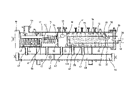
Fig. .2 shows a side view of the housing 15 in accordance
with fig- 1 in section. The housing 15 is designed as a.
hollow cylinder which is closed with cover flanges 29, 30
CA 02734371 2011-01-31
- 11 -
at its ends. The in-feeds 21 and 22 are. arranged
eccentrically which results in a tangential inflow of the
natural gas into the housing 15.
The housing 15 in the form of a hollow cylinder comprises
the reactor container 14, the mixing chamber 16 and the
separator 17. These fitting are separated from each other.
by means of transverse bases 31, 32, 33 and 34, whereby
transverse bases 33 and 34 have a number of apertures,
whereby they are similar to a sieve or perforated metal
plate.
Whereas transverse bases 31 and 32 have a pure separating
function, transverse bases 33 and 34 act as transitions due
to the number of apertures. Transverse base 33 is the
transition for the direct entry into the mixing chamber 16
of the natural gas, heated through the catalytic
combustion, flowing out of the reactor container 14.
Transverse base 34 allows the preheated burnable gas
flowing through pipe connection 36 to enter the reactor
container 14 and then, on flowing through the catalytic
converter bed, contained as packing in the reactor
container 14, to take up the heat released by the catalytic
Conversion of the mixed in oxygen.
The burnable gas heated to activation temperature in the
preheating station 7 is taken via the pipe connection 36.
passing through the cover flange 29 into the interior of
the reactor container 14. After flowing through the
catalytic packing, in which the catalytic reaction takes
place with the generation of heat, part of the hot gases is
drawn in via the suction line 12 (fig. 1) of the jet pump
Of the preheating station 7 in order to provide the heat
energy required for the functioning of the preheating
station V.
CA 02734371 2011-01-31
- 12 -
The draw-in opening 136 of the suction line 12 is located
in the vicinity of the transverse base 33 forming the
transition 23 (fig.1) from the reactor container 14 to the
mixing chamber 16.
From the reactor container 14 the suction line 12 also runs
through the cover flange 29 after its offset 37 visible
here.
At the same time the cover flange 29 acts as a carrier for
the measuring sticks 38 and 39, fitted with temperature
sensors, which extend into the reactor container 14 in
parallel to the longitudinal axis of the reactor container
14. In addition, at least one heating rod 40 is provided as
an option which can be used to heat the reactor bed, for
example before starting up the device.
Arranged in the annular space 35 between the housing 15 and
the outer mantle of the reactor container 14 there are
guide elements 41, in this case a strand element in the
form of a vertically welded on flat steel band arranged in
spiral fashion around the outer mantle of the reactor
chamber 14, here indicated by means of a dashed line.
The cold gas fed in via in-feed 22 flows around. the reactor
container 14 through the annular space 35 and cools the
reactor so that the condensate is already separated.
The mixer chamber drain 24 leading to the separator chamber
25 is located in the transverse base 32 which separates the
mixing chamber 16 from the separator 17.
The transverse base 31 divides the separator 17 into two
adjacent areas; a first area containing the mixing chamber
drain 24 and which is fitted with several cyclone
separators 42 for coarse separation, and a second area in
which several filter elements 43 are provided.
CA 02734371 2011-01-31
- 13 -
The gas flowirg. out of the mixing chamber 16 flows through
the area with the cyclone separators 42, and then through
the area with the filter elements 43. Finally the gas flows
out of the device via the Outlet 44 in conditioned state
and thereby suitable for use.
The reactor container 14, mixing chamber 16 and separator
17 have condensate drains 47 which remove the condensate
into an external condensate trap 46. The condensate trap 46
is divided into three chambers areas 48, 49 and 50, in
which the condensates, depending on their degree of
Contamination by hydrocarbons, are collected separately
which makes their disposal/processing more cost-effective.