Note : Les descriptions sont présentées dans la langue officielle dans laquelle elles ont été soumises.
CA 02734400 2011-02-16
WO 2010/020384 PCT/EP2009/005943
Diffusion and/or Filtration Device
Technical Field
The present disclosure relates to a diffusion and/or fil-
tration device, such as a dialyser, hemofilter, or ultra-
filter, having improved flow characteristics. The invention
also relates to an end cap for the device.
Description of the Related Art
Diffusion and/or filtration devices used as dialysers, he-
mofilters, or ultrafilters generally encompass a casing
comprising a tubular section with end caps capping the
mouths of the tubular section. A bundle of hollow fiber
membranes is usually arranged in the casing in a way that a
seal is provided between the first flow space formed by the
fiber cavities and a second flow space surrounding the mem-
branes on the outside. One problem with the design of the
inflow and/or outflow chambers connected to the first flow
space, i.e., to the hollow fiber bundle, is to distribute
the liquid evenly between the individual fibers of the hol-
low fiber bundle, and to avoid the formation of dead zones
in the inlet chamber, i.e. areas where the flow velocity is
approximately zero. Blood clots may form in such dead
zones, and after completion of a dialysis treatment, some
of the patient's blood remains there. As the cross-section
of the inlet is smaller than the cross-section of the fiber
bundle, the velocity of the blood-flow is reduced. Hence,
the blood may be exposed to mechanical stress due to the
CA 02734400 2011-02-16
WO 2010/020384 - 2 - PCT/EP2009/005943
velocity gradient between the inlet and the fibers. The de-
sign of the end caps therefore is of particular importance
to ensure optimal operation of the device. Several propo-
sals have been made in the prior art:
DE 26 46 358 Al describes a filter device where the end
caps have a tangential inlet and the blood is carried in a
channel in circulation through the ends of the hollow fi-
bers. Blood flows tangentially through the hollow fiber
ends. To achieve the most uniform possible distribution of
liquid, only the areas of the casting compound in overflow
circulation are provided with hollow fibers, while the rest
of the core area does not have any fibers. This achieves
uniform loading of the fibers but also results in a rela-
tively low capacity or less than optimum utilization of the
filter device on the whole due to the lack of hollow fibers
at the center of the casing. To achieve a uniform rate of
circulation of blood in the channel, the cross-sectional
area of the channel in one embodiment decreases in the di-
rection of flow.
DE 198 57 850 Al discloses a filtration device where the
inlet or outlet chamber, respectively, is adjacent to an
essentially circular or semicircular channel arranged ap-
proximately centrally with the hollow fiber bundle which
communicates with an inlet or outlet of the filter device
and is open in the direction towards the ends of the hollow
fibers and has a cross-sectional area that decreases in the
direction of flow and an outside diameter which is smaller
than the diameter of the hollow fiber bundle. As the inlet
is located parallel to the plane of the fiber ends, the di-
rection of the liquid flow is changed by 90 degrees in the
end area of the inlet, causing turbulences and mechanical
stress on the blood.
CA 02734400 2011-02-16
WO 2010/020384 - 3 - PCT/EP2009/005943
-
EP 0 844 015 A2 discloses a filter device having two flow
spaces, a first space formed by tubular or capillary tube
passages of a hollow-fiber bundle which has been poured in-
to a molding compound at its ends, and a second space
formed by the housing surrounding the fiber bundle. first
space is sealed off by caps placed on the molding com-
pounds, with sealing devices placed over the peripheral a-
reas of the molding compounds. Caps for the ends of the
first space seal to the molding compound and have a connec-
tion piece providing inflow/outflow access to the first
space. A second set of caps, overlapping the first caps,
has a connection piece providing inflow/outflow access to
the second space. The edges of the second caps are joined
to the housing in a fluid tight manner, so that between the
first and second set of caps, interspaces are formed which
are connected to the second space. As is apparent from Fig.
1 of the reference, the basal plane of the end cap is pa-
rallel to the plane of the molding compound comprising the
fibers and the blood-flow through the inlet is deflected at
a sharp edge in the cap. Turbulent flow and mechanical
stress on the blood are the consequence.
EP-A 0 305 687 teaches a dialyser in which the inlet of the
chambers connected to the hollow fiber bundle is arranged
axially, with the axis of the flow channel running approx-
imately through the mid point of the hollow fiber bundle.
As apparent from the figures in the reference, the cross-
section of the liquid path in the end cap continuously in-
creases between the inlet and the level part of the inside
of the end cap, hence there are no sharp edges. The level
part is not parallel to the plane formed by the ends of the
hollow fibers, but slightly inclined. However, no further
details are given in the reference.
CA 02734400 2011-02-16
WO 2010/020384 - 4 - PCT/EP2009/005943
Another factor that influences the flow properties of the
device is the design of the hollow fiber membrane bundle.
As the membranes form the interface between the first and
the second flow space of the device and mass transfer pro-
cesses occurring through the membranes affect the liquid
flow in the flow spaces of the device, the material of the
hollow fiber membranes and the geometry of both the indi-
vidual fibers and the fiber bundle as a whole are important
factors.
EP 0 305 787 Al discloses a permselective asymmetric mem-
brane suitable for hemodialysis, hemodiafiltration and he-
mofiltration of blood, comprised of a hydrophobic first po-
lymer, e.g. polyamide, a hydrophilic second polymer, e.g.
polyvinylpyrrolidone, and suitable additives. The membrane
has a three-layer structure, comprising a first layer in
the form of dense, rather thin skin, responsible for the
sieving properties, a second layer in the form of a sponge
structure, having a high diffusive permeability and serving
as a support for said first layer, and a third layer in the
form of a finger structure, giving the membrane a mechani-
cal stability.
WO 2004/056459 Al discloses a membrane suitable for hemo-
dialysis, comprising at least one hydrophobic polymer, e.g.
polyarylethersulf one, and at least one hydrophilic polymer,
e.g. polyvinylpyrrolidone. The outer surface of the hollow
fiber has pores in the range of 0.5 - 3 pm and the number
of pores in the outer surface is in the range of 10,000 to
150,000 pores per mm2.
WO 01/60477 A2 teaches a filter device, preferably for he-
modialysis, consisting of a cylindrical filter housing and
a bundle of curled hollow fibers arranged in the filter
housing. The curled hollow fibers have an essentially sinu-
CA 02734400 2014-12-04
soidal texture and a wavelength A that is limited by the formula 5d <A < L/12
* (1 +
2D/L)-1, wherein A represents the wavelength of the curled hollow fibers, d
represents the exterior diameter of the hollow fibers, L represents the
effective
length of the hollow fibers, and D represents the diameter of the fiber
bundle. The
5 amplitude of the curling has a value between d/5 and A/5.
Summary
It is an object of the present invention to improve upon a generic filter
device, so that
a more homogeneous liquid flow within the device is obtained and the formation
of
areas where the liquid velocity is nearly zero (dead zones) is avoided.
According to one aspect of the invention, a diffusion and/or filtration device
having
improved flow characteristics is provided. The device comprises a housing, a
bundle
of hollow fiber membranes arranged within the housing, and end caps sealing
the
mouths of the housing.
According to a further aspect, the invention relates to an end cap for a
diffusion
and/or filtration device. The end cap is characterized by certain geometric
parameters.
According to another aspect, the invention also relates to an end cap for at
least one of a diffusion device and a filtration device, the end cap having an
inner
surface which is axially symmetrical with regard to a longitudinal axis of the
end cap
and the inner surface having the form of a funnel and comprising, in the
direction of
increasing diameter towards an interior of the end cap, a first section (I)
taking the
form of a cylinder or a truncated cone, a middle section (II) taking the form
of a torus
segment, the radius R of the torus segment being in the range of from 4 mm to
10
mm, and a third section (III) taking the form of a truncated cone, wherein the
CA 02734400 2014-12-04
5a
diameter D of the base of the third section (III) and the angle a between the
base of the third section and a lateral surface of the third section (III) and
the volume
V calculated according to the formula
V = (1rD1/4) X (h ¨ X tan a)
6 ( I )
wherein h is the minimum distance between an inner surface of the third
section (III)
of the end cap and the plane defined by ends of the hollow fiber membranes,
when
the end cap is mounted on the at least one of a diffusion device and a
filtration
device, meet the condition:
1000 mm2 x ¨> a X (tan a)2-1- 6
V 1 (II)
with al = 100.
According to yet another aspect, the invention also relates to at least one of
a
diffusion device and a filtration device, the device comprising a housing, a
bundle of
semi-permeable hollow fiber membranes arranged within the housing, and end
caps,
each end cap having an inner surface which is axially symmetrical with regard
to a
longitudinal axis of the end cap and the inner surface having the form of a
funnel and
comprising, in the direction of increasing diameter towards an interior of the
end cap,
a first section (I) taking the form of a cylinder or a truncated cone, a
middle section
(II) taking the form of a torus segment, the radius R of the torus segment
being in
the range of from 4 mm to 10 mm, and a third section (III) taking the form of
a
truncated cone, wherein the diameter D of the base of the third section (III)
and the
angle a between the base of the third section and a lateral surface of the
third
section (III) and the volume V calculated according to the formula
CA 02734400 2014-12-04
5b
V = (IrD7/ 4) x (h 4- ¨ X tan a)
6 (I)
wherein h is the minimum distance between an inner surface of the third
section (III)
of the end cap and the plane defined by ends of the hollow fiber membranes,
when
the end cap is mounted on the at least one of a diffusion device and a
filtration
device, meet the condition:
D
1000 mart- X ¨> a' x (tan cr)2 + 6
11
(II)
with a1=100 sealing the mouths of the housing.
Brief Description of the Drawings
Figure 1 shows a schematic cross-sectional side view of an embodiment of the
end
cap of the invention. The shaded area represents a portion of a filtration
device
sealed by the end cap;
Figure 2 shows a side, cross-sectional view of another embodiment of the end
cap of
the invention;
CA 02734400 2011-02-16
WO 2010/020384 - 6 - PCT/EP2009/005943
Figure 3a shows a side, partially cross-sectional view of
an embodiment of the diffusion and/or filtration device of
the invention; Figure 3b shows a side, partially cross-
sectional view of another embodiment of the diffusion
and/or filtration device of the invention;
Figure 4 shows an experimental set up for imaging dialys-
ers to measure the blood-side flow;
Figure 5 shows an experimental set up for imaging dialys-
ers to measure the dialysate-side flow.
Figure 6 shows blood compartment dynamic flow images ob-
tained by magnetic resonance imaging for a Revaclear Max
dialyzer.
Figure 7 shows blood compartment dynamic flow images ob-
tained by magnetic resonance imaging for a Revaclear di-
alyzer.
Figure 8 shows blood compartment dynamic flow images ob-
tained by magnetic resonance imaging for a Polyflux 210H
dialyzer.
Figure 9 shows blood compartment dynamic flow images ob-
tained by magnetic resonance imaging for a Optiflux F160NR
dialyzer.
Figure 10 shows blood compartment dynamic flow images ob-
tained by magnetic resonance imaging for a Optiflux F200NR
dialyzer.
CA 02734400 2011-02-16
WO 2010/020384 - 7 - PCT/EP2009/005943
Figure 11 shows dialysate compartment dynamic flow images
obtained by magnetic resonance imaging for a Revaclear Max
dialyzer.
Figure 12 shows dialysate compartment dynamic flow images
obtained by magnetic resonance imaging for a Revaclear di-
alyzer.
Figure 13 shows dialysate compartment dynamic flow images
obtained by magnetic resonance imaging for a Polyflux 210H
dialyzer.
Figure 14 shows dialysate compartment dynamic flow images
obtained by magnetic resonance imaging for a Optiflux
F160NR dialyzer.
Figure 15 shows dialysate compartment dynamic flow images
obtained by magnetic resonance imaging for a Optiflux
F200NR dialyzer.
Detailed Description
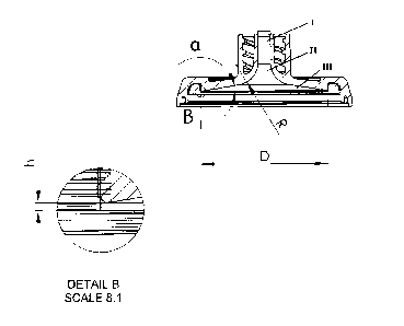
Figure 1 shows an embodiment of the end cap proposed in the
present disclosure. As shown in Figure 1, the end cap com-
prises an inlet or outlet, respectively, for a liquid, ar-
ranged axially in the center of the end cap. A two-start
thread which fits a standard blood-line connector is pro-
vided round the inlet or outlet, as the case may be. Start-
ing from the mouth of the end cap, the inner diameter of
the inlet or outlet, as the case may be, is constant or in-
creases linearly in a first section (I) of the end cap,
then widens gradually, with a constant curvature R, in a
second section (II) until the inner surface includes a pre-
determined angle a with the horizontal. The diameter then
increases linearly in a third section (III), until a prede-
CA 02734400 2011-02-16
WO 2010/020384 - 8 - PCT/EP2009/005943
termined diameter D is reached. At diameter D, the fluid
compartment formed by the inside of the end caps and the
lumen of the hollow fiber membranes, when the end caps are
placed on the mouths of the tubular housing of the device,
is sealed off by a gasket ring placed in a circular groove
provided in the end caps. When the device is assembled, the
minimum distance between the inner surface of the end cap
and the plane defined by the ends of the hollow fiber mem-
branes is h.
The inner surface of the end cap is axially symmetrical
with regard to the longitudinal axis of the inlet/outlet,
which is also the longitudinal axis of the end cap. The in-
ner surface has the form of a funnel comprising, in the di-
rection of increasing diameter, a first section (I) taking
the form of a cylinder or a truncated cone, a middle sec-
tion (II) taking the form of a torus segment, and a third
section (III) taking the form of a truncated cone.
It has been found that in order to achieve optimized flow
characteristics, the following conditions have to be met by
the diameter D of the base of the third section (III), the
angle a between the base and the lateral surface of the
third section (III), and the volume V calculated according
to the formula
nD2
_______________________________________ =(h + ¨Dtana) (I),
4 6
wherein h is the minimum distance between the inner surface
of the third section (III) of the end cap and the plane de-
fined by the ends of the hollow fiber membranes, when the
end cap is mounted on the diffusion and/or filtration de-
vice:
1,000.D/V > a1 (tan a)2 + 6 (II)
CA 02734400 2011-02-16
WO 2010/020384 - 9 - PCT/EP2009/005943
with al= 100; D and h are given in mm.
In another embodiment of the invention, al = 120. In still
another embodiment, al= 140.
In one embodiment of the invention, the following condi-
tions are additionally met:
1,000.D/V < a2.(tan a)2 + 9 (III)
with a2 = 1,400. V is calculated according to formula II;
and D and h are given in mm.
In another embodiment of the invention, a2 = 1,200. In
still another embodiment, a2 = 1,000.
In one embodiment of the invention, the diameter D is in
the range of from 15 to 60 mm.
In another embodiment of the invention, the following con-
ditions are met:
tan a
90=10-6MM-2 < ______________________ < 120=10-6 mm-2
(IV)
D2
In one embodiment of the invention, the radius R of the
middle section (II), i.e., the curvature R, is in the range
of from 4 mm to 10 mm, e.g. from 5 mm to 9 mm, in particu-
lar from 6 to 8 mm.
In one embodiment of the invention, the distance h has a
value in the range of from 1.5 mm to 2.0 mm.
In one embodiment of the invention, the aperture of the
first section (I) from the inlet to the middle section is
CA 02734400 2011-02-16
WO 2010/020384 - 10 - PCT/EP2009/005943
in the range of from 0 to 40, e.g. from 10 to 3 , in par-
ticular from 1.5 to 2.5 .
In a particular embodiment of the end cap of the invention
shown in Figure 2, the top of the first section (I), i.e.,
the inlet of the end cap, has a diameter of 3.7 + 0.1 mm,
the aperture of the first section (I) from the inlet to the
middle section is 2.0 + 0.1 0, R is 7.0 + 0.1 mm, a is 9.53
+ 0.05 , i.e. the aperture of the third section (III) is
160.94 + 0.10 , D is 39.8 + 0.05 mm. When the end cap is
mounted on a diffusion and/or filtration device, h is 1.75
+ 0.08 mm.
Another aspect of the present invention is a diffusion
and/or filtration device comprising a housing (1), a bundle
of semi-permeable hollow fiber membranes (2) arranged with-
in the housing, and end caps (4a,4b) according to the
present invention sealing the mouths of the tubular hous-
ing.
Figure 3 shows an embodiment of the diffusion and/or fil-
tration device of the invention comprising:
a) housing means (1), said housing means defining a lon-
gitudinally extending internal chamber including a
first end and a second end;
b) a bundle of semi-permeable hollow fiber membranes (2)
disposed within said internal chamber, said hollow
fibers extending longitudinally from said first end
of said housing to said second end of said housing,
said hollow fiber membranes having an outer surface,
and a first end and a second end corresponding to
said first end and said second end of said internal
chamber;
CA 02734400 2011-02-16
WO 2010/020384 - 11 - PCT/EP2009/005943
c) end wall means (3) supporting said first and second
ends of said hollow fiber membranes within said in-
ternal chamber so as to sealingly separate said first
and second ends of said hollow fiber membranes from
said outer surface of said hollow fiber between said
first and second ends thereof;
d) first inlet means for the introduction of a fluid in-
to said first end of said housing means, said first
inlet means being defined by a first end cap (4a)
covering said first end of said housing;
e) first outlet means for the evacuation of a fluid from
said second end of said housing means, said first
outlet means being defined by a second end cap (4b)
covering said second end of said housing, said first
and second end caps being applied to said first and
second ends of said housing in a fluid-tight manner;
f) second outlet means (5) for the evacuation of a fluid
from said internal chamber at a location between said
first and second end of said housing means;
g) at least one ring member (6) disposed between said
end wall means and said housing means at one of said
first and second ends of said internal chamber, said
ring member being in direct contact with said housing
and having a shape corresponding to said housing and
defining a cavity between said ring member and said
hollow fiber membranes, the coefficient of adhesion
between said end wall means and said ring member be-
ing lower than the coefficient of adhesion between
said end wall means and said housing, whereby the
structural integrity of said housing means and the
seal between said ends of said hollow fiber membranes
and said outer surface of said hollow fiber membranes
is enhanced; and
h) at least one sealing ring (7) interposed between said
end wall and said first inlet means.
CA 02734400 2013-11-28
,
12
In one embodiment, the diameter of the housing is not uniform. The housing has
a
middle section where the diameter is smaller than at the ends of the housing.
Accordingly, the distances between the individual hollow fibers are smaller in
the
middle section of the device than at the end faces of the hollow fiber bundle.
In
another embodiment, the housing has a diameter-expanding portion allowing
hollow
fiber membranes to be placed in a way that the distances between the hollow
fiber
membranes are gradually increased toward the end faces of the hollow fiber
bundle.
The housing and end caps of the device of the invention are usually made of a
transparent polymer, e.g. polyethylene, polypropylene, polyesters like PET or
PBT,
polymethyl-(meth)acrylate, polystyrene (HIPS) or polycarbonate. The potting
material for the hollow fiber membranes usually is polyurethane. In one
embodiment
of the device of the invention, the housing and caps are made of
polycarbonate, the
potting material forming the end wall means (3) is made of polyurethane and
the
sealing rings (7) are made of silicone rubber.
The hollow fiber membranes used in the device of the invention can be those
described in EP 0 568 045 Al, EP 0 168 783 Al, EP 0 082 433 A2, WO
2004/056469 Al, EP 0 750 936 Al, or WO 86/00028 Al. These membranes are
manufactured from polymeric synthetic materials; they have an asymmetric
structure
with high diffusive permeability (clearance) and have water filtration
capabilities in
ultrafiltration applications in the range of low flux to high flux. Suitable
examples are
the membrane based on polysulfone and polyvinylpyrrolidone (PVP) disclosed in
EP
0 750 936 Al and the 4-layer membrane
CA 02734400 2011-02-16
WO 2010/020384 - 13 - PCT/EP2009/005943
based on polyethersulfone, PVP and polyamide disclosed in
WO 2004/056469 Al.
In general, the semipermeable hollow fiber membrane is
based on at least one hydrophobic polymer and at least one
hydrophilic polymer. Said at least one hydrophobic polymer
is preferably chosen from the group consisting of polyamide
(PA), polyaramide (PAA), polyarylethersulfone (PAES), po-
lyethersulfone (PES), polysulfone (PSU), polyarylsulf one
(PASU), polycarbonate (PC), polyether, polyurethane (PUR),
polyetherimide and copolymers of said polymers. In a par-
ticular embodiment, the hydrophobic polymer is polysulf one,
polyethersulfone or a mix of polyarylethersulfone and po-
lyamide. In another particular embodiment, polyethersulfone
is used for preparing the membrane.
Said at least one hydrophilic polymer is usually chosen
from the group consisting of polyvinylpyrrolidone (PVP),
polyethylene glycol (PEG), polyglycolmonoester, water so-
luble cellulosic derivates, polysorbate and polyethylene-
polypropylene oxide copolymers. In a particular embodiment,
polyvinylpyrrolidone is used for preparing the membrane,
wherein the polyvinylpyrrolidone consists of a low molecu-
lar weight component having a molecular weight of below 100
kDa and a high molecular weight component having a molecu-
lar weight of 100 kDa or more.
One embodiment of the membrane consists of 80 - 99 % by
weight of said hydrophobic polymer, for instance polyether-
sulfone, and 1 - 20 96 by weight of said at least one hydro-
philic polymer, for instance polyvinylpyrrolidone (PVP).
The PVP consists of a high molecular weight P. 100 kDa) and
a low molecular weight (< 100 kDa) component, wherein the
PVP consists of 10 - 45 weight-9s, based on the total weight
of PVP in the membrane, of a high molecular weight compo-
CA 02734400 2011-02-16
WO 2010/020384 - 14 - PCT/EP2009/005943
nent, and of 55 - 90 weight-%, based on the total weight of
PVP in the membrane, of a low molecular weight component.
In one embodiment, the membrane is further characterized by
a very specific four-layer structure and by having a diffu-
sive permeability of chloride of about 19.1-10-4 cm/sec
measured at 37 C. The diffusive permeability can be deter-
mined according to E. Klein, F. Holland, A. Lebeouf, A.
Donnaud, J. K. Smith, "Transport and Mechanical Properties
of Hemodialysis Hollow Fibers", Journal of Membrane Science
1 (1976) 371 - 396, especially pages 375 - 379.
The inner layer of the four-layer structure, i.e. the blood
contacting layer and the inner surface of the hollow fiber
membrane, is a separation layer in the form of a dense, ra-
ther thin layer having, in a particular embodiment, a
thickness of less than 1 pm and a pore size in the nano-
scale range. To achieve high selectivity, the pore channels
with the responsible pore diameters are short, i.e. below
0.1 pm. The pore channel diameter has a low variation in
size. The defined pore structure is achieved by selection
of the composition of the polymer, the composition and con-
dition of the precipitation media in the center fluid and
by the condition and composition of the surrounding envi-
ronment of the fiber leaving the spinning nozzle.
The next layer in the hollow fiber membrane is the second
layer having the form of a sponge structure and serves as a
support for said first layer. In a particular embodiment,
the thickness of this layer ranges from about 1 to 15 pm.
Then, there is the third layer having the form of a finger
structure. It provides for mechanical stability on the one
hand; on the other hand it has, through the high void vo-
lume, a very low resistance of transport of molecules
CA 02734400 2011-02-16
WO 2010/020384 - 15 - PCT/EP2009/005943
through the membrane. During the process, the voids are
filled with water, and the water gives a lower resistance
for diffusion and convection than a matrix with a sponge-
filled structure having a lower void volume. Accordingly,
the third layer provides mechanical stability to the mem-
brane. In a particular embodiment, the thickness of this
layer ranges from about 20 to 60 pm.
The fourth layer in this embodiment of the membrane is the
outer layer, which is characterized by a homogenous and
open pore structure with a defined surface roughness. The
openings of the pores are in the size range of 0.5 - 3 pm,
further the number of pores on the outer surface is in the
range of 10,000 to 150,000 pores per mm2, e.g. in the range
of 20,000 to 80,000 pores per mm2, in particular 35,000 to
55,000 pores per mm2. In a particular embodiment, this
fourth layer has a thickness of about 1 to 10 pm.
This four-layer design provides for a high selectivity,
which means, a high potential to separate molecules, which
are close in their size, for example, to separate albumin,
which is to be retained, from a 32-microglobulin and Factor
D.
The membrane, due to its specific preparation and characte-
ristics as described before, is characterized by a high
convective permeability Lp and a high diffusive permeabili-
ty for small molecules, such as, for example, urea or chlo-
ride (Pci). The Lp is in the range of from 56-10-4 to 84-10-4
cm/bar-s, e.g. from 70 to 80-10-4 cm/bar-s. The chloride
permeability Pi is in the range of from 18-10-4 to 21-10-4
cm/s, e.g. from 19-10-4 to 20-10-4 cm/s.
The membrane is further characterized by a high selectivi-
ty, i.e. a high removal rate for middle molecular weight
CA 02734400 2011-02-16
WO 2010/020384 - 16 - PCT/EP2009/005943
molecules, while at the same time the loss of protein of
higher molecular weight is minimized. The membrane has a
sieving coefficient (SCmy,,) for myoglobin (17,053 Dalton) in
aqueous solution of from 85 to 90 %, and a sieving coeffi-
cient (SCAibu) for albumin (66,248 Dalton) in aqueous solu-
tion of 9 % or less. The selectivity in aqueous solution of
the membrane according to the invention, calculated as the
ratio of SCmyo/SCAibu, accordingly ranges from 9.4 to 10 or
higher.
The membrane can be prepared by a solvent phase inversion
spinning process, comprising the steps of
a) said at least one hydrophilic polymer and said at
least one hydrophobic polymer being dissolved in at
least one solvent to form a polymer solution;
b) said formed polymer solution being extruded through
an outer ring slit of a nozzle with two concentric
openings;
c) a center fluid being extruded through the inner open-
ing of the nozzle; and thereafter
d) said membrane being washed and preferably dried and
sterilized by steam treatment.
The polymer solution coming out through the outer slit
opening is, on the outside of the precipitating fiber, ex-
posed to a humid steam/air mixture comprising a solvent in
a content of between 0 and 10 % by weight, related to the
water content.
In one embodiment, the spinning solution for preparing a
membrane preferably comprises between 12 and 15 weight-96 of
CA 02734400 2011-02-16
WO 2010/020384 - 17 - PCT/EP2009/005943
polyethersulfone or polysulfone as hydrophobic polymer and
to 10 weight-% of PVP, wherein said PVP consists of a low
and a high molecular PVP component. The total PVP contained
in the spinning solution consists of from 22 to 34 weight-
and particularly from 25 to 30 weight- % of a high molecular
weight component and of from 66 to 78 weight-%, particular-
ly from 70 to 75 weight-% of a low molecular weight compo-
nent. Examples for high and low molecular weight PVP are
PVP K85/K90 and PVP K30, respectively.
In one embodiment, the polymer solution used in the process
for preparing a membrane further comprises 66 - 86 % by
weight of solvent and 1 - 5 % by weight of suitable addi-
tives. Suitable additives are, for example, chosen form the
group of water, glycerol and/or other alcohols. Water is
especially preferred and is present in the spinning solu-
tion in an amount of between 1 - 8 % by weight, particular-
ly in an amount of between 2 - 5 % by weight. The solvent
used in the process preferably is chosen from the group
comprising n-methylpyrrolidone (NMP), dimethyl acetamide
(DMAC), dimethyl sulf oxide (DMSO), dimethyl formamide
(DMF), butyrolactone and mixtures of said solvents. NMP is
especially preferred. The spinning solution advantageously
is homogeneously degassed and filtered.
The center fluid or bore liquid which is used for preparing
the membrane comprises at least one of the above-mentioned
solvents and a precipitation medium chosen from the group
of water, glycerol and other alcohols. Most preferably the
center fluid consists of 45 - 70 % by weight precipitation
medium and 30 - 55 % by weight of solvent. In one embodi-
ment, the center fluid consists of 51 - 57 % by weight of
water and 43 - 49 % by weight of NMP. Again, the center
fluid advantageously is degassed and filtered.
CA 02734400 2011-02-16
WO 2010/020384 - 18 - PCT/EP2009/005943
The viscosity of the polymer solution generally is in the
range of from 2,500 to 7,000 mPa.s, e.g. from 3,500 to
6,000 mPa-s.
In one embodiment of the process for preparing a membrane,
the temperature of the spinneret is 30 - 70 C, e.g. 45 -
55 C, the temperature of the spinning shaft is 25 - 65 C,
e.g. 40 - 50 C. The distance between the opening of the
nozzle and the precipitation bath is in the range of from
25 to 1,500 mm, e.g. from 550 to 1,100 mm. The precipita-
tion bath has a temperature of 10 - 40 C, particularly of
15 - 25 C. The spinning velocity generally is in the range
of 25 - 80 m/min, e.g. 30 - 60 m/min. The temperature of
the humid steam/air mixture is at least 15 C, preferably
at least 30 C, and at most 75 C, but is preferably not
higher than 60 C. Further, the relative humidity in the
humid steam/air mixture is between 60 and 100 %.
In another embodiment of the process, the humid steam/air
mixture comprises a solvent in an amount of from 0 to 5 %
by weight, related to the water content. In one embodiment,
the humid steam/air mixture comprises a solvent in an
amount of from 0 to 3 % by weight, related to the water
content. The effect of the solvent in the temperature-
controlled steam atmosphere is to control the speed of pre-
cipitation of the fibers. lf less solvent is employed, the
outer surface will obtain a more dense surface, and if more
solvent is used, the outer surface will have a more open
structure. By controlling the amount of solvent within the
temperature-controlled steam atmosphere surrounding the
precipitating membrane, the amount and size of the pores on
the outer surface of the membrane can be modified and con-
trolled.
CA 02734400 2011-02-16
WO 2010/020384 - 19 - PCT/EP2009/005943
In one embodiment, the membrane is subsequently washed in
water to remove waste components, and then dried at tempe-
ratures of 150 - 280 C, for instance 180 - 260 C. Such
drying provides for an adequate evaporation of water and a
defined shrinkage of pores. The final treatment consists of
rinsing the membrane in water at a temperature of 50 -
95 C, e.g. 80 - 90 C, and subsequently drying the mem-
brane at temperatures of 30 - 65 C, e.g. 55 - 65 C.
In one embodiment, the membrane is steam sterilized at tem-
peratures above 121 C for at least 21 minutes.
In one embodiment, the hollow fiber membrane has an inner
diameter of between 180 and 200 pm. In a particular embodi-
ment, the inner diameter is approximately 190 pm. The wall
thickness of the hollow fiber generally is in the range of
from 30 to 40 pm, e.g. approximately 35 pm.
In a particular embodiment of the invention, the bundle of
hollow fibers (2) has a diameter of 38 mm and a length of
236 mm and comprises approximately 12,000 fibers. The indi-
vidual fibers have an outer diameter of 0.26 mm, an inner
diameter of 0.19 mm and a wall thickness of 35 pm. The fi-
ber bundle has a surface area of 1.8 m2. The individual fi-
bers are curled having a sinusoidal texture with a wave-
length of 7.5 mm and an amplitude of 0.3 mm. The membrane
is made of polyethersulf one and polyvinylpyrrolidone con-
sisting of a low molecular weight component having a mole-
cular weight less than 100 kDa and a high molecular weight
component having a molecular weight of 100 kDa or more.
In another particular embodiment of the invention, the bun-
dle of hollow fibers (2) has a diameter of 38 mm at the
ends and a diameter of 34 mm in the central section and a
length of 236 mm and comprises approximately 9,600 fibers.
CA 02734400 2011-02-16
WO 2010/020384 - 20 - PCT/EP2009/005943
The individual fibers have an outer diameter of 0.26 mm, an
inner diameter of 0.19 mm and a wall thickness of 35 pm.
The fiber bundle has a surface area of 1.4 m2. The indivi-
dual fibers are curled having a sinusoidal texture with a
wavelength of 7.5 mm and an amplitude of 0.3 mm. The mem-
brane is made of polyethersulf one and polyvinylpyrrolidone
consisting of a low molecular weight component having a mo-
lecular weight less than 100 kDa and a high molecular
weight component having a molecular weight of 100 kDa or
more.
The device in vitro has sieving coefficients (measured ac-
cording to EN 1283) of 1.0 for vitamin B12, 1.0 for Inulin,
0.7 for P2-microglobuline, and < 0.01 for albumin. The UF
coefficient (ml/h * mmHg) in vitro, measured according to
EN 1283, with bovine blood (hematocrit = 32 96, protein = 60
g/l, at 37 C) has a value of 60 + 20 96. The maximum flow
resistance in the blood compartment, measured according to
EN 1283 at UF = 0 ml, with bovine blood (hematocrit = 32 %,-,
protein = 60 g/l, at 37 C), is less than 100 mmHg at QB =
200 ml/min, less than 135 mmHg at QB = 300 ml/min, less
than 170 mmHg at QB = 400 ml/min, and less than 205 mmHg at
QB = 500 ml/min. The maximum flow resistance in the dialy-
sate compartment, measured according to EN 1283 at UF = 0
ml, with dialysate at 37 C, is less than 45 mmHg at C/3 =
500 ml/min, less than 60 mmHg at QB = 700 ml/min, and less
than 65 mmHg at QB = 800 ml/min. The residual blood volume
is less than 1 ml.
Table 1 lists the values for the clearance in vitro of sev-
eral substances contained in blood, measured according to
EN 1283 at UF = 0 ml/min. The accuracy of the measurement
is + 10 96.
CA 02734400 2011-02-16
WO 2010/020384 - 21 - PCT/EP2009/005943
Table 1 Clearance in hemodialysis (HD)
QB [ml/min] 200 300 400 SOO
Clearance [ml/min] of urea
(QD=500 ml/min) 198 282 339 376
(QD=700 ml/min) 199 291 365 422
Clearance [ml/min] of creatinin
(413=500 ml/min) 195 265 311 341
(QD=700 ml/min) 197 278 339 384
Clearance [ml/min] of phosphate
(QD=500 ml/min) 191 256 297 324
(QD=700 ml/min) 195 270 324 365
Clearance [ml/min] of vitamin B12
(QD=500 ml/min) 158 191 211 225
_
(QD=700 ml/min) 164 205 231 251
It will be understood that the features mentioned above and
those described hereinafter can be used not only in the
combination specified but also in other combinations or on
their own, without departing from the scope of the present
invention.
The present invention will now be described in more detail
in the examples below. It is to be understood that the ex-
amples are not intended to limit the scope of the present
invention and are merely an illustration of a preferred em-
bodiment of the invention.
CA 02734400 2011-02-16
WO 2010/020384 - 22 - PCT/EP2009/005943
Examples
Uniform distribution of fluid flows within the dialyzer is
critical for optimal clearance of uremic toxins and avoid-
ance of residual blood loss and clotting (thrombogenicity).
Magnetic Resonance Imaging (MRI) was used to evaluate (a)
the distribution and dynamics of blood flow in five types
of hemodialysers, and (b) the distribution and dynamics of
dialysate flow in five types of hemodialysers. The dialys-
ers studied were
o PES/PVP, 12,000 fibers, fiber length 260 mm, effective
surface area 1.8 m2, D = 39.8 mm, a = 9.530, h = 1.75
mm, outer diameter of the housing 40.7 mm (Revaclear
Max, Gambro)
o PES/PVP, 9,600 fibers, fiber length 260 mm, effective
surface area 1.4 m2, D = 39.8 mm, a = 9.530, h = 1.75
mm ,outer diameter of the housing 36.6 mm (Revaclear ,
Gambro)
o PES/PVP, 12,000 fibers, fiber length 300 mm, effective
surface area 2.1 m2, D = 48 mm, a - 10.8 , h = 1.75
mm, outer diameter of the housing 51.9 mm (Polyflux
210H, Gambro)
o PSf/PVP, 10,300 fibers, fiber length 255 mm, effective
surface area 1.5 m2, D = 45.7 mm, a = 8.3 , h = 2.6
mm, outer diameter of the housing 43.8 mm (Optiflux
160NR, Fresenius)
o PSf/PVP, 14,000 fibers, fiber length 255 mm, effective
surface area 2.0 m2, D = 54.0 mm, a = 7.2 , h = 2.6
mm, outer diameter of the housing 51.6 mm (Optiflux
200NR, Fresenius)
All imaging was performed using a 3.0T Siemens Trio, MR Im-
ager. The CP Head coil was used for both signal excitation
CA 02734400 2011-02-16
WO 2010/020384 - 23 - PCT/EP2009/005943
and reception as its size allowed for complete coverage of
the dialysers. The experimental set up for measuring the
blood-side flow is shown in Figure 4 while Figure 5 shows
the experimental set up for measuring the dialysate flow.
For both the dialysate and the blood-side flow the fluid
used was water which was circulated from a 20 1 reservoir
via a roller ball pump. The pulsations in the flow created
by the roller ball pump were damped by inserting two Cole-
Parmer pulse dampeners into the circuit immediately after
the pump. The flow rate was measured using a Cole-Parmer
flow gauge which was calibrated by measuring the rate for
filling a graduate cylinder to a specified volume. To
achieve fluid flows of 350 ml/min or 500 ml/min, gauge set-
tings of 105 or 149, respectively, were used.
For each dialyser, dynamic MR imaging of fluid flow was
performed. Images were acquired in rapid acquisition while
ml of a small molecular weight contrast agent (Magnev-
istm, C28H54GdN5020; MW = 938) was injected as a bolus into
either the dialysate or the blood-side flow. The resulting
images demonstrate the passage of the bolus of contrast
agent as a diminishment in the image intensity where high
concentrations of the agent were present
Dynamic images were acquired in the sagittal (through the
inlet and outlet of the dialysate side) and coronal (longi-
tudinal section perpendicular to the sagittal plane) planes
of each dialyser. The images were acquired with a single-
shot rapid acquisition, repeated echo (RARE) sequence. A
single plane image was acquired in each case with a repeti-
tion time of 500 ms. In total 64 images were acquired and
the contrast media was acquired after approximately 10 im-
ages had been acquired. A volume of 5 ml of MagnevistTM di-
CA 02734400 2014-12-04
24
luted to 250 mM was injected into the inlet of either the blood-side or the
dialysate-
side flow.
The contrast media was carried by the fluid flow and passed rapidly through
the
dialyser. Its presence affected the image intensity because it lowered the
relaxation
time T2 of the fluid. Thus on the image the contrast media was noted by the
transient
decrease in image intensity. The images were analyzed by comparing the image
intensity of every frame to the image intensity averaged over the first
several frames.
Regions where the image intensity declined substantially were colored to
indicate
the presence of the contrast media.
The results are shown in Fig. 6 through 15, Fig. 6 - 10 showing the flow in
the blood
compartment of the respective dialysers, while Fig. 11 -15 show the flow in
the
dialysate compartment of the respective dialysers, where throughout Figures 6-
15,
uppermost images of these figures relate to results obtained with the prior
art,
whereas bottommost images relate to results obtained with the present
invention.
Revaclear showed the greatest uniformity of both blood and dialysate flows.
Excellent flow dynamics were also seen with the Revaclear Max. The pictures
demonstrate the superior blood and dialysate flow characteristics and dynamics
of
the end cap and the diffusion and/or filtration device of the invention
(bottommost
images of Figures 6-15) in comparison to those known in the art (uppermost
images
of Figures 6-15).
The scope of the claims should not be limited by the preferred embodiments set
forth
in the examples, but should be given the broadest interpretation consistent
with the
description as a whole.