Note : Les descriptions sont présentées dans la langue officielle dans laquelle elles ont été soumises.
CA 02734674 2011-03-22
Title of the invention: SHREDDER
CROSS-REFERENCE TO RELATED APPLICATION
[0001] This application claims the benefit of U.S. Provisional Patent
Application Serial No. 61/317,013 filed on March 24, 2010 hereby
incorporated herein by reference in its entirety.
FIELD OF THE INVENTION
[0002] The invention relates to a shredder, and more particularly to a
shredder capable of destroying stapled and unstapled documents.
BACKGROUND OF THE INVENTION
[0003] A common type of shredder has a shredder mechanism contained
within a housing that is mounted atop a container. The shredder mechanism
typically includes a series of cutter elements. The cutter elements shred a
material (e.g. sheets of paper) fed therein and discharge the shredded
material downwardly into the container. Prior art shredders have a
predetermined capacity or amount of material that can be shredded in one
pass between the cutter elements. Typically, the material is fed into
the shredder mechanism manually. Thus, when a user operates the shredder,
the user can only manually insert, at a given time, the predetermined amount
of material that can be shredded in one pass between the cutter elements.
With manual-feed shredders, the user spends time feeding the predetermined
amount of the material, thus taking away from a productivity of the user.
[0004] Other prior art shredders are designed for automatic feeding.
The auto-feed shredders include a tray in which a stack of material can be
placed. A feed mechanism advances the material into the shredding
mechanism. This type of shredder is desirable in an office setting for
productivity reasons, as the user can bad the material into the tray and then
leave the shredder to operate. However, when the material has been stapled
and the staple(s) have not been removed, the feed mechanism can advance
too many sheets of the material into the shredder mechanism. Thus, a
jamming or an overloading of the cutter elements of the shredder mechanism
1
CA 02734674 2011-03-22
may occur. To prevent such an occurrence, prior art shredders either require
the user to remove the staple(s) from the material prior to inserting the
material into the shredder or require the material to be inserted into the
tray of
the shredder in a predetermined orientation (e.g., stapled portion of the
material positioned away from the cutter elements) such that the staple(s) can
be removed by the shredder.
[0005] Accordingly, it would be desirable to produce a shredder including a
shredder mechanism, which is capable of destroying stapled and unstapled
material, wherein the material can be manually or automatically fed into the
shredder mechanism in any orientation.
SUMMARY OF THE INVENTION
[0006] In concordance and agreement with the present invention, a
shredder including a shredder mechanism, which is capable of destroying
stapled and unstapled material, wherein the material can be manually or
automatically fed into the shredder mechanism in any orientation, has
surprisingly been discovered-
[0007] In an embodiment, the shredder comprises: a housing including a
feed bed formed therein, wherein the feed bed receives a material to be
shredded therein; a shredder mechanism disposed in the housing, the
shredder mechanism including at least one cutter element to convert the
material to a shredded material; and a feed mechanism disposed in the
housing, the feed mechanism including a first roller and a second roller
located adjacent an intermediate portion of the feed bed, the first roller and
the second roller cooperating to advance an intermediate portion of the
material in a direction towards the shredder mechanism.
[0008] In another embodiment, the shredder comprises: a housing
including a feed bed formed therein, wherein the feed bed receives a material
to be shredded therein; a shredder mechanism disposed in the housing, the
shredder mechanism including at least one cutter element to convert the
material to a shredded material; a feed mechanism disposed in the housing,
the feed mechanism including a first roller and a second roller, wherein one
of
the first roller and the second roller contacts an intermediate portion of the
2
CA 02734674 2011-03-22
material to advance the intermediate portion of the material therebetween in a
direction towards the shredder mechanism; and a panel coupled to the
housing to provide access to the feed bed, the feed bed defined by an
advancement mechanism coupled to the panel, wherein the advancement
mechanism causes the material in the feed bed to be pressed against one of
the first roller and the second roller.
[0009] In another embodiment, the shredder comprises: a housing
including a feed bed formed therein, wherein the feed bed receives a material
to be shredded therein; a shredder mechanism disposed in the housing, the
shredder mechanism including at least one cutter element to convert a
material to a shredded material; a feed mechanism disposed in the housing,
the feed mechanism including a first roller, a second roller, and a third
roller,
wherein the first roller and the third roller contact an intermediate portion
of
the material to advance the intermediate portion of the material between the
first roller and the second roller in a direction towards the shredder
mechanism, and wherein a direction of rotation of the second roller is
opposite
a direction of rotation of the first roller and a direction of rotation of the
third
roller is the same as the direction of rotation of the second roller; and a
panel
coupled to the housing to provide access to the feed bed, the feed bed
defined by an advancement mechanism coupled to the panel, wherein the
advancement mechanism causes the material in the feed bed to be pressed
against the first roller and the third roller.
BRIEF DESCRIPTION OF THE DRAWINGS
[0010] The above, as well as other advantages of the present disclosure,
will become readily apparent to those skilled in the art from the following
detailed description, particularly when considered in the light of the
drawings
described herein.
[0011] FIG. 1 is a fragmentary side perspective view of a shredder
according to an embodiment of the invention showing a panel of the shredder
in an open position; and
[0012] FIG. 2 is a cross-sectional side elevational view of the shredder
illustrated in FIG. 1 taken along line 2-2 of FIG. 1 and showing the panel of
3
CA 02734674 2011-03-22
the shredder in a closed position and with a material to be shredded disposed
therein.
DETAILED DESCRIPTION OF EXEMPLARY
EMBODIMENTS OF THE INVENTION
[0013] The following detailed description and appended drawings describe
and illustrate various embodiments of the invention. The description and
drawings serve to enable one skilled in the art to make and use the invention,
and are not intended to limit the scope of the invention in any manner.
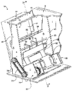
[0014] FIG. 1 shows a shredder 10 according to an embodiment of the
present invention. The shredder 10 operates to destroy or shred material 12
such as a sheet or stack of stapled paper, a sheet or stack of wrinkled paper,
envelopes, credit cards, compact discs, and the like, for example. It Is
understood that the shredder 10 may have any suitable size and shape as
desired. The shredder 10 includes a housing 9 formed around a frame 11 and
disposed on top of a container (not shown). The container receives the
material 12 shredded by the shredder 10. The container may be a waste bin
or an enclosure for receiving a removable waste bin, for example.
[0015] The housing 9 of the shredder 10 includes a shredder mechanism
20 disposed therein. The shredder mechanism 20 includes at least one motor
22 and a plurality of cutter elements 24. It is understood that the motor 22
can
be any motor as desired such as an electrically powered motor, for example.
As illustrated in FIG_ 2, the cutter elements 24 are disposed on a pair of
parallel shafts 26, 27. In the embodiment shown, the motor 22 operates to
rotatably drive the shafts 26, 27 in opposite directions, including the cutter
elements 24, and shred the material 12 fed into the shredder mechanism 20.
The cutter elements 24 are disposed on the shafts 26, 27 in any suitable
manner and are rotated in an interleaving relationship for shredding the
material 12. The shredder mechanism 20 may also include a sub-frame 28 for
mounting the shafts 26, 27 and the motor 22 to the housing 9.
10016] A pair of guides 29, 30 forms a throat 31 of the shredder
mechanism 20 to receive and guide the material 12 into the cutter elements
24. The shredder mechanism 20 may further include a second throat (not
4
CA 02734674 2011-03-22
shown) which cooperates with an opening (not shown) formed in the housing
9 to permit a user to manually insert the material 12 into the shredder
mechanism 20. In a non-limiting example, at least one of the guides 29, 30
cooperates with another guide (not shown) to form the second throat of the
shredder mechanism 20- In another non-limiting example, a second pair of
guides (not shown) forms the second throat of the shredder mechanism 20. It
is understood that the guides 29, 30 can be formed from any suitable material
as desired such as a metal material, a plastic material, and the like, for
example. It is further understood that the guides 29, 30 can be formed
integrally with the housing 9 if desired.
[0017] In the embodiment shown, the housing 9 further includes a panel 32
to provide access to a feed bed 33. The panel 32 is coupled to the housing 9
to facilitate a feeding of the material 12 from the feed bed 33 into the
cutter
elements 24 of the shredder mechanism 20. In a non-limiting example, the
panel 32 is pivotally coupled to the housing 9, wherein the panel 32 is
selectively positionable between an open position, as shown in FIG. 1, and a
closed position, as shown in FIG. 2. In the open position of the panel 32, the
panel 32 is tilted away from the housing 9 and the feed bed 33 is accessible
to a user of the shredder 10, allowing the user to load the material 12 into
the
feed bed 33. In the dosed position of the panel 32, the panel 32 is
substantially flush with the housing 9 and the feed bed 33 is inaccessible to
the user of the shredder 10, allowing the shredder mechanism 20 to be
operated. A handle (not shown) may be provided on the panel 32 if desired.
[0018] In the embodiment shown, the feed bed 33 is defined by an
advancement mechanism 42. The advancement mechanism 42 is selectively
positionable within the panel 32 to hold and position the material 12 for
shredding. Although the advancement mechanism 42 shown is coupled to
the panel 32 by a pair of fasteners 34, it is understood that the advancement
mechanism 42 can be coupled to the panel 32 by any means as desired. A
plurality of urging members 36 is disposed between a wall of the panel 32 and
the advancement mechanism 42. The urging members 36 cause the
advancement mechanism 42 to travel within the panel 32 in a direction away
from the wall 37 of the panel 32. Accordingly, the advancement mechanism
CA 02734674 2011-03-22
42 causes the material 12 to advance and be pressed against a pair of cross-
members 38, 39. The cross-members 38, 39 shown extend between side
supports 40, 41 of the frame 11. Additional or fewer urging members 36 than
shown can be employed as desired. It is understood that the urging members
36 can be any suitable urging members as desired such as a leaf spring, a
compression spring, a baffle, and the like, for example. It is further
understood
that each of the urging members 36 can exert a different force on the
advancement mechanism 42 if desired- The advancement mechanism 42 is
caused to travel within the panel 32 in an opposite direction towards the wall
37 of the panel 32 as the material 12 is loaded into the feed bed 33.
[0019] As illustrated in FIG. 2, the advancement mechanism 42 is a
substantially planar plate having a buckling member 44 disposed thereon to
cause the material 12 to bend. The buckling member 44 may be integrally
formed with the advancement mechanism 42 if desired. The buckling member
44 shown is an elongate bar extending between opposite side edges of the
advancement mechanism 42 and offset from a lower peripheral edge 52.
Although the buckling member 44 has a substantially hemispheric cross-
sectional shape, it is understood that the buckling member 44 can have any
suitable shape and size as desired. The advancement mechanism 42 shown
includes an arm member 46 laterally extending from an upper portion thereof-
The arm member 46 acts as a stop for the material 12 during an operation of
the shredder 10.
[0020] The advancement mechanism 42 may further include a low-friction
zone 54 and a high-friction zone 56. The low-friction zone 54 is located
between the buckling member 44 and the lower peripheral edge 52. The low-
friction zone 54 can be produced from any suitable material or surface
treatment as desired to minimize a coefficient of friction and facilitate a
sliding
of the material 12 such as a polytetrafluoroethylene (PTFE) material, a
chemical process (e.g. employing a corrosive acid for chemically polishing), a
mechanical process (e.g. coating or mechanically polishing), and the like, for
example. In the embodiment shown, the low-friction zone 54 is produced by a
piece of styrene material disposed in and extending between the opposite
side edges of the advancement mechanism 42. The high-friction zone 56 is
6
CA 02734674 2011-03-22
located between the buckling member 44 and the arm member 46. The high-
friction zone 56 can be produced from any suitable material or surface
treatment as desired to maximize the coefficient of friction and militate
against
a sliding of the material 12 such as a elastomer material, a chemical process
(e-g. employing corrosive acid for chemically texturing), a mechanical process
(e.g. rippling, grooving, or mechanically texturing), and the like, for
example.
In the embodiment shown, the high-friction zone 56 is produced by a piece of
cork material disposed in and extending between the opposite side edges of
the advancement mechanism 42.
[0021] The shredder 10 further includes a feed mechanism 60 for causing
the material 12 from the feed bed 33 to be fed into the cutter elements 24 for
shredding. As shown in FIG. 2, the feed mechanism 60 includes a rotatable
first roller 62 and a rotatable second roller 64 located adjacent an
intermediate
portion of the feed bed 33. The rollers 62, 64 are mounted to respective axles
66, 68. The first roller 62 is positioned between the buckling member 44 and
the cross-member 38 for engaging the material 12 and feeding the material 12
into the throat 31 of the shredder mechanism 20. The second roller 64 is
disposed above and adjacent the first roller 62 for engaging the first roller
62
and feeding the material 12 into the throat 31 of the shredder mechanism 20.
In the embodiment shown, the axle 68 of the second roller 64 is coupled to
the motor 22 for effecting a rotational movement thereof and the first roller
62
is free. Accordingly, the second roller 64 rotates in a first direction,
thereby
causing the first roller 62 to rotate in an opposite second direction. As
illustrated in FIG. 2, the second roller 64 rotates in a counter-clockwise
direction as indicated by arrow A, thereby causing the first roller 62 to
rotate in
a clockwise direction as indicated by arrow B. It is understood, however, that
the first roller 62 can be coupled to the motor 22 for effecting a rotational
movement thereof and the second roller 64 is free, if desired. It is further
understood that both the first roller 62 and the second roller 64 can be
coupled to the motor 22 for effecting the rotational movement thereof, if
desired. The rollers 62, 64 may be coupled to the motor 22 or a separate
motor (not shown) for effecting the rotational movement thereof by any means
as desired such as a chain 70 and gears 74 as shown in FIG. 1, for example.
7
CA 02734674 2011-03-22
[00221 In another embodiment, the feed mechanism 60 further includes a
rotatable third roller (not shown). The third roller is positioned above the
second roller 04 and below the cross-member 39. The third roller engages the
material 12 and further bends the material 12 for feeding the material 12
between the rollers 62, 64. In a non-limiting example, the third roller
rotates in
the same direction as the second roller 64, The third roller can be coupled to
the motor 22 or a separate motor (not shown) for effecting a rotational
movement thereof.
[00231 In another embodiment, the buckling member 44 is offset from an
upper peripheral edge of the advancement mechanism 42 and the arm
member 46 laterally extends from a lower portion thereof. The low-friction
zone 54 is located between the buckling member 44 and the upper peripheral
edge of the advancement mechanism 42 and the high-friction zone 56 is
located between the buckling member 44 and the arm member 46.
Additionally, the first roller 62 is disposed between the cross-member 39 and
the buckling member 44 and the second roller 64 is disposed below and
adjacent the first roller 62 for engaging the first roller 62. Thus, the
second
roller 64 rotates in a clockwise direction and the first roller 62 rotates in
a
counter-clockwise direction. The shredder 10 of the embodiment may further
include the third roller. The third roller is positioned below the second
roller 64
and above the cross-member 38, wherein the third roller abuts the material
12. The third roller rotates in the same direction as the second roller 64.
Thus,
the third roller rotates in a clockwise direction.
[0024] As illustrated in FIGS. 1 and 2, the feed mechanism 60 may further
include at least one buckling guide 80. The buckling guide 80 further
facilitates a bending of the material 12 and directs the material 12 between
the rollers 62, 64. It is understood that the buckling guide 80 can have any
size and shape and can be formed from any suitable material as desired such
as a metal material, a plastic material, and the like, for example. It is
further
understood that the buckling guide 80 can be integrally formed with the
housing 9 if desired.
[0025] Additional components necessary for operation of the shredder 10
such as a control unit, a power source, electrical wiring, a locking mechanism
8
CA 02734674 2011-03-22
for the panel 32, and the like, for example, may be disposed in the shredder
as desired. It is also understood that the shredder 10 may include various
sensors and switches for controlling the operation of the shredder 10 such as
a power switch, a sensor provided in the housing 9 for detecting an open or
closed position of the panel 32, a sensor provided in the feed bed 33 for
detecting a presence of the material 12 therein, and the like, for example.
[0026] In operation, the panel 32 is pivoted to the open position allowing
the user to load the material 12 into the feed bed 33. After loading the
material
12 into the feed bed 33, the panel 32 is pivoted to the closed position- In
the
closed position of the panel 32, each of the urging members 36 exert a force
on the advancement mechanism 42 of the feed bed 33 to press the material
12 against the cross-members 38, 39 and the first roller 62_ The shredder
mechanism 20 and the feed mechanism 60 are then activated (e.g. upon
closure of the panel 32, via a sensor, or manually).
[0027] When the shredder 10 is activated, the motor 22 causes the second
roller 64 of the feed mechanism 60 to rotate in the counter-clockwise
direction. The second roller 64 engages the first roller 62 and causes the
first
roller 62 to rotate in the clockwise direction. Rotational movement of the
first
roller 62 causes a portion intermediate a top edge and a bottom edge of a
first
sheet of the material 12 to slide upward over the low-friction zone 54 and
contact the buckling member 44. The buckling member 44 causes the
intermediate portion of the first sheet of the material 12 to bend towards and
be fed between the rollers 62, 64_ The intermediate portion of the first sheet
of
the material 12 may be further directed towards the rollers 62, 64 by the at
least one buckling guide 80. In the embodiment shown, the high-friction zone
56 and the arm member 46 of the advancement mechanism 42 militate
against upward movement of the first sheet of the material 12 in the feed bed
33 to further facilitate a bending of the intermediate portion of the first
sheet of
the material 12.
[00281 The motor 22 may also cause the third roller to rotate in the
counter-clockwise direction. Rotational movement of the third roller causes
the intermediate portion of the first sheet of the material 12 to slide
downward.
9
CA 02734674 2011-03-22
Accordingly, the intermediate portion of the first sheet of the material 12 is
caused to further bend towards and be fed between the rollers 62, 64.
[0029] The intermediate portion of the first sheet of the material 12 is then
grasped between the rollers 62, 64, causing the first sheet in its entirety to
be
fed therebetween. Accordingly, the intermediate portion of the material 12 is
fed between the rollers 62, 64 prior to the edges of the material 12 being fed
therebetween. The first sheet then advances through the throat 31 of the
shredder mechanism 20 formed by the guides 29, 30 and into the cutter
elements 24, The cutter elements 24 convert the first sheet of the material 12
into shredded material, which falls by gravity into the container. The feed
mechanism 60 continues to feed each sheet of the material 12 into the cutter
elements 24 until a desired number or all of the sheets of the material 12
have
been converted into shredded material.
[0030] Referring to another embodiment of the invention, the motor 22
causes the second roller 64 of the feed mechanism 60 to rotate in the
clockwise direction. The second roller 64 engages the first roller 62 and
causes the first roller 62 to rotate in the counter-clockwise direction.
Rotational movement of the first roller 62 causes the intermediate portion of
the first sheet of the material 12 to slide downward over the low-friction
zone
54 and contact the buckling member 44. The high-friction zone 56 and the
arm member 46 of the advancement mechanism 42 militate against
downward movement of the first sheet of the material 12 in the feed bed 33 to
further facilitate a bending of the intermediate portion of the first sheet of
the
material 12. The motor 22 may also cause the third roller to rotate in the
clockwise direction. Rotational movement of the third roller causes the
intermediate portion of the first sheet of the material 12 to slide upward.
[0031] When the material 12 is stapled along and/or adjacent a bottom
edge thereof, the cross-member 38 extends into a path of which the stapled
material 12 is drawn because the stapled material 12 is pressed against the
cross-member 38 by the urging members 36. Thus, as a sheet of the stapled
material 12 is grasped by the rollers 62, 64 and fed into the shredder
mechanism 20, the cross-member 38 intercedes by providing resistance to
the stapled material 12. Accordingly, the resistance provided by the cross-
CA 02734674 2011-03-22
member 38 allows the sheet to be stripped or sheared from the staple(s)
disposed along and/or adjacent the bottom edge of the material 12. In the
embodiment shown, the cross-member 38 provides resistance by contacting a
portion of the sheet above the staple(s) or contacting the staple(s) to hold
the
stapled material 12.
[0032] When the material 12 is stapled along and/or adjacent a top edge
thereof, the cross-member 39 extends into a path of which the stapled
material 12 is drawn because the stapled material 12 is pressed against the
cross-member 39 by the urging members 36. Thus, as a sheet of the stapled
material 12 is grasped by the rollers 62, 64 and fed into the shredder
mechanism 20, the cross-member 39 intercedes by providing resistance to
the stapled material 12. Accordingly, the resistance provided by the cross-
member 39 allows the sheet to be stripped or sheared from the staple(s)
disposed along and/or adjacent the top edge of the material 12. In the
embodiment shown, the cross-member 39 provides resistance to the stapled
material 12 by contacting a portion of the sheet below the staple(s) or
contacting the staple(s) to hold the stapled material 12.
[0033] Alternatively, the user can manually insert the material 12 through
the opening formed in the housing 9 and into the second throat of the
shredder mechanism 20. Accordingly, the material 12 for shredding bypasses
the panel 32 and the feed mechanism 60. This feature may be advantageous,
for example, where the user simply wants to shred a limited amount of
material 12, compact discs, credits cards, thick envelopes, and the like, for
example.
[0034] The invention is not limited to the embodiments described and
represented in the attached drawings. Modifications are still possible, in
particular with regard to the configuration of the various elements or
substituting equivalent techniques without departing as such from the scope
of protection of the invention.
11