Note : Les descriptions sont présentées dans la langue officielle dans laquelle elles ont été soumises.
CA 02735312 2011-03-21
APPARATUS FOR OIL EXTRACTION FROM OIL SANDS
FIELD OF THE INVENTION
The present invention relates to a system and apparatus for the
separation of oil and the like from oil sands either as an in situ oil sands
formation or
in a bed of oil sands which have been placed in a vessel subsequent to mining
for
processing.
BACKGROUND
As described in Canadian Patent Application No. 2,445,173, filed April
24, 2002 for an In Situ Recovery From a Tar Sands Formation, hydrocarbons
obtained from subterranean formations are often used as energy resources, as
feedstocks, and as consumer products. Concerns over depletion of available
hydrocarbon resources have led to development of processes for more efficient
recovery, processing and/or use of available hydrocarbon resources. In situ
processes may be used to remove hydrocarbon materials from subterranean
formations. Chemical and/or physical properties of hydrocarbon material within
a
subterranean formation may need to be changed to allow hydrocarbon material to
be
removed from the subterranean formation. The chemical and physical changes may
result from in situ reactions that produce removable fluids, composition
changes,
solubility changes, phase changes, and/or viscosity changes of the hydrocarbon
material within the formation. A fluid may be, but is not limited to, a gas, a
liquid, an
emulsion, a slurry, and/or a stream of solid particles with flow
characteristics similar to
liquid flow. Large deposits of heavy hydrocarbons (e.g., heavy oil and/or tar)
contained within formations (e.g., in oil sands) are found in North America,
South
America, and. Asia. Tar sand deposits may be mined. Surface processes may
separate bitumen from sand and/or other material removed along with the
CA 02735312 2011-03-21
2
hydrocarbons. The separated bitumen may be converted to light hydrocarbons
using
conventional refinery methods. Mining and upgrading tar sand is usually
substantially
more expensive than producing lighter hydrocarbons from conventional oil
reservoirs.
In Canadian Patent Application No. 2,445,173, heat is provided from
one or more heat sources to a portion of the oil sands formation. The heat may
be
allowed to transfer from the heat source(s) to a selected section of the
formation to
pyrolyze at least some hydrocarbons within the selected section. A mixture of
hydrocarbons of a selected quality may be produced from the selected section
by
controlling production of the mixture to adjust the time that at least some
hydrocarbons are exposed to pyrolysis temperatures in the formation.
Canadian Patent 1,037,862 by James Adamson discloses a system and
apparatus for extracting oil and the like from oil sands in situ. The method
includes
circulating steam, solvent or fluids through the sand while constantly
agitating the
sand to scrub and wash the oil free whereupon the oil is carried back to the
surface. A
vibrating probe assembly is utilized which is highly manoeuverable and which
fluidizes
the sand immediately surrounding same thus facilitating the movement of the
probe
and assisting in the scrubbing and separating action of the solvents or steam
upon the
sand. The probe includes means for extending same into the sand to the bottom
of a
well bore so that the vibration in conjunction with the probe configuration
moves the
probe through the sand in a horizontal plane or, if desired, up and down at an
angle
from the horizontal. The voids remaining in the clean sand are filled with
water so that
the probe floats on the surface of the water. The oil which has been separated
from
the sand floats on the water to the well bore and thence is elevated to the
surface by
the pressure of the steam, solvent or fluid circulation.
CA 02735312 2011-03-21
3
As describe above, there has previously been some effort to develop
methods and systems to economically produce hydrocarbons, hydrogen, and/or
other
products from oil sands formations. At present, however, there are still many
oil sands
formations from which hydrocarbons, hydrogen, and/or other products cannot be
economically produced. Thus, there is still a need for improved methods and
systems
for production of hydrocarbons, hydrogen, and/or other products from various
oil
sands formations.
SUMMARY OF THE INVENTION
According to one aspect of the invention there is provided an apparatus
for the separation of oil and the like from oil sands comprising:
a probe member which is elongated in a longitudinal direction, the probe
member including a front surface portion which is substantially semi-circular
about a
longitudinal axis of the probe member and a tapered rear surface portion which
is
gradually reduced in thickness in a rearward direction from the front surface
portion
towards a rear apex opposite the front surface portion;
a probe support assembly which is arranged to suspend the probe
member within the oil sands and to control the direction of the probe member;
a vibrating mechanism arranged to vibrate the probe member;
the probe member being supported by the probe support assembly so
as to be arranged to move through the oil sand in a forward direction
perpendicular to
the longitudinal axis of the probe member when vibrated by the vibrating
mechanism;
the rear surface portion of the probe member having a greater surface
area than the front surface portion such the that front surface portion
presents less
frictional resistance to the oil sand than the rear surface portion;
an injector conduit supported by the probe support assembly and
CA 02735312 2011-03-21
4
arranged to convey an oil-from-sand separating fluid to the probe member and
to
discharge the oil-from-sand separating fluid into oil sands adjacent to the
probe; and
a plurality of spaced apart protrusions on at feast the front surface
portion of the probe member so as to protrude generally radially outwardly
from the
longitudinal axis of the probe member.
In some embodiments, the protrusions comprise elongated ribs formed
on the rear surface portion so as to extend generally in the rearward
direction. The
elongated ribs may extend from the front surface portion towards the apex at
an
inclination to the rearward direction. More particularly, when the probe
member is
supported at one end on the probe support assembly such that the probe member
extends outward from the probe support assembly in the longitudinal direction
towards the opposing end, the elongated ribs may be oriented to decrease in
distance
from the probe support assembly in the rearward direction from the front
surface
portion to. the rear apex. In this instance, the ribs act to maintain tension
on the probe
member relative to the probe support as it moves forwardly through the oil
sands.
Alternatively, the protrusions may comprise elongated ribs formed on
the front surface portion so as to extend generally in the longitudinal
direction of the
probe member. The elongated ribs in this instance may be ramped in profile so
as to
increase in thickness protruding outward from the surface portion in the
rearward
direction so as to increase friction in the rearward direction only to better
encourage
forward movement of the probe member when vibrated. The ribs may also have a
substantially constant thickness between opposed longitudinally extending
edges
while still being effective at increasing friction in the rearward direction.
In yet further embodiments, the protrusions may be formed on at least
the front surface portion so as to be spaced apart from one another in a first
direction
CA 02735312 2011-03-21
corresponding to the longitudinal direction and spaced apart from one another
in a
second direction oriented perpendicularly to the longitudinal direction. In
this instance
each protrusion preferably extends outward from the surface portion of the
probe
member to a respective pointed apex to assist in breaking up clumps of
material
5 encountered by the probe member. Furthermore, each protrusion may be formed
of
metal and may have a greater hardness than the surface portion of the probe
member
upon which the protrusion is supported.
According to a second aspect of the present invention there is provided
an apparatus for the separation of oil and the like from oil sands comprising:
a probe member which is elongated in a longitudinal direction, the probe
member including a front surface portion which is substantially semi-circular
about a
longitudinal axis of the probe member and a tapered rear surface portion which
is
gradually reduced in thickness in a rearward direction from the front surface
portion
towards a rear apex opposite the front surface portion;
a probe support assembly which is arranged to suspend the probe
member within the oil sands and to control the direction of the probe member;
a vibrating mechanism arranged to vibrate the probe member;
the probe member being supported by the probe support assembly so
as to be arranged to move through the oil sand in a forward direction
perpendicular to
the longitudinal axis of the probe member when vibrated by the vibrating
mechanism;
the rear surface portion of the probe member having a greater surface
area than the front surface portion such the that front surface portion
presents less
frictional resistance to the oil sand than the rear surface portion;
an injector conduit supported by the probe support assembly and
arranged to convey an oil-from-sand separating fluid to the probe member and
to
CA 02735312 2011-03-21
6
discharge the oil-from-sand separating fluid into oil sands adjacent to the
probe; and
a tail portion extending generally rearwardly from the rear apex and
having a substantially constant thickness.
The tail section may be rigid and arranged to be substantially fixed in
orientation relative to the surface portions of the probe member. The tail
section may
oriented parallel to or transversely to the rearward direction depending upon
the
desired packing effect.
When the probe member includes a longitudinally extending mounting
flange at the rear apex, preferably the tail section is arranged to be
selectively
mounted on the mounting flange.
According to a third aspect of the present invention there is provided an
apparatus for the separation of oil and the like from oil sands comprising:
a plurality of probe members which are elongated in respective
longitudinal directions, each probe member including a front surface portion
which is
substantially semi-circular about a longitudinal axis of the probe member and
a
tapered rear surface portion which is gradually reduced in thickness in a
rearward
direction from the front surface portion towards a rear apex opposite the
front surface
portion;
a vibrating mechanism arranged to vibrate the probe members;
the rear surface portion of each probe member having a greater surface
area than the front surface portion such the that front surface portion
presents less
frictional resistance to the oil sand than the rear surface portion;
a probe support assembly which is arranged to suspend the probe
members within the oil sands and to control the direction of the probe
members;
the probe support assembly supporting the probe members thereon
CA 02735312 2011-03-21
7
such that:
the probe members are circumferentially spaced about a central
axis of the probe support assembly;
each probe member extends upwardly at a radially outward
inclination from a bottom end of the probe support assembly in a working
position;
and
respective forward directions of the probe members are oriented
in a circumferential direction about the probe support assembly such that the
probe
members are arranged to move through the oil sand in the circumferential
direction
about the central axis of the probe support assembly when vibrated by the
vibrating
mechanism; and
an injector conduit supported by the probe support assembly and
arranged to convey an oil-from-sand separating fluid to the probe member and
to
discharge the oil-from-sand separating fluid into oil sands adjacent to the
probe.
Each probe member may be pivotal relative to the probe support
assembly between the working position and a deploying position oriented
parallel to
and alongside the probe support assembly.
Preferably the injector conduit is supported on the probe support so as
to be centrally located relative to the probe members.
According to another aspect of the present invention there is provided
an apparatus for the separation of oil and the like from oil sands comprising:
a plurality of probe members which are elongated in respective
longitudinal directions, each probe member including a front surface portion
which is
substantially semi-circular about a longitudinal axis of the probe member and
a
tapered rear surface portion which is gradually reduced in thickness in a
rearward
CA 02735312 2011-03-21
8
direction from the front surface portion towards a rear apex opposite the
front surface
portion;
a vibrating mechanism arranged to vibrate the probe members;
the rear surface portion of each probe member having a greater surface
area than the front surface portion such the that front surface portion
presents less
frictional resistance to the oil sand than the rear surface portion;
a probe support assembly which is arranged to suspend the probe
members within the oil sands and to control the direction of the probe
members;
the probe support assembly supporting the probe members thereon
such that:
the probe members are circumferentially spaced about a
substantially vertical central axis of the probe support assembly;
the probe members are substantially parallel to one another; and
respective forward directions of the probe members are oriented
in a circumferential direction about the probe support assembly such that the
probe
members are arranged to move through the oil sand in the circumferential
direction
about the central axis of the probe support assembly when vibrated by the
vibrating
mechanism; and
an injector conduit supported by the probe support assembly and
arranged to convey an oil-from-sand separating fluid to the probe member and
to
discharge the oil-from-sand separating fluid into oil sands adjacent to the
probe.
Preferably the injector conduit is supported on the probe support so as
to be centrally located relative to the probe members in this instance.
The probe members may be interconnected by link members extending
generally in the circumferential direction between adjacent ones of the probe
CA 02735312 2011-03-21
9
members at longitudinally spaced positions between opposing ends of the probe
members.
According to another aspect of the present invention. there is provided
an apparatus for the separation of oil and the like from oil sands comprising:
a probe member which is elongated in a longitudinal direction, the probe
member including a front surface portion which is substantially semi-circular
about a
longitudinal axis of the probe member and a tapered rear surface portion which
is
gradually reduced in thickness in a rearward direction from the front surface
portion
towards a rear apex opposite the front surface portion;
a probe support assembly which is arranged to suspend the probe
member within the oil sands and to control the direction of the probe member;
a vibrating mechanism arranged to vibrate the probe member;
the probe member being supported by the probe support assembly so
as to be arranged to move through the oil sand in a forward direction
perpendicular to
the longitudinal axis of the probe member when vibrated by the vibrating
mechanism;
the rear surface portion of the probe member having a greater surface
area than the front surface portion such the that front surface portion
presents less
frictional resistance to the oil sand than the rear surface portion; and
an injector conduit supported by the probe support assembly and
arranged to convey an oil-from-sand separating fluid to the probe member and
to
discharge the oil-from-sand separating fluid into oil sands adjacent to the
probe;
the vibrating mechanism comprising first and second longitudinally
extending conduits, the first conduit being in communication with a source
arranged to
be maintained at a constant pressure and the second conduit being in
communication
with a source arranged to be cyclically varied between an upper pressure and a
lower
CA 02735312 2011-03-21
pressure, the first and second conduits being separated by a common resilient
divider
wall extending longitudinally along a full length of the probe member such
that the
divider wall reciprocates with the cyclical pressure variation in the second
conduit.
Some embodiments of the invention will now be described in
5 conjunction with the accompanying drawings in which:
BRIEF DESCRIPTION OF THE DRAWINGS
Figure 1 is a partly sectional elevational view of a first embodiment of a
probe support assembly for supporting a probe member for separation of oil
from oil
sands.
10 Figure 2 is a cross sectional view of a first embodiment of the probe
member.
Figure 3 is a cross sectional view of a first embodiment of the vibrating
mechanism of the probe member.
Figure 4 is a sectional perspective view of a first embodiment of
protrusions on the probe member.
Figure 5 and Figure 6 are cross sectional views of alternate
embodiments of the tail section of the probe member.
Figures 7 through 10 are sectional perspective views of alternate
embodiments to the protrusions on the probe members.
Figure 11 is a sectional elevational view of a second embodiment of the
probe support assembly.
Figure 12 is a side elevational view of a third embodiment of the probe
support assembly in a working position.
Figure 13 is a top plan view of the assembly according to Figure 12 in
the working position.
CA 02735312 2011-03-21
11
Figure 14 is a side elevational view of the assembly of Figure 12 in a
deploying position.
Figures 15 and 16 are perspective views of a further embodiment of the
probe support assembly.
Figure 17 is an elevational view of a further embodiment of the probe
support assembly.
In the drawings like characters of reference indicate corresponding parts
in the different figures.
DETAILED DESCRIPTION
Referring to the accompanying figures, there is illustrated a probe
member 100 for use in separation of oil and the like from an oil sands
formation or in
separation of oil from an oil sands bed placed in a processing vessel for
processing
subsequent to being mined. In each instance, a probe support assembly 102
supports the probe member 100 in the oil sands.
Proceeding therefore to describe the invention in detail, reference
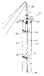
should first be made to FIG. 1 which shows schematically, an oil sand
formation
including the overburden 10, the sedimentary rock or base 11 of the formation
and the
sedimentary bed 12 of oil sand which may be up to 200 feet in depth.
The probe member 100 is supported by the probe support assembly in
the oil sands formation such that vibration of the probe member 100 causes the
probe
member to be displaced through the oil sands in a forward direction of the
probe
member.
Although various embodiments of the probe member and the probe
support assembly are described and illustrated in the following, it is to be
understood
CA 02735312 2011-03-21
12
that any embodiment of the probe member 100 can be applied to any embodiment
of
the probe support assembly 102.
In each instance the probe member 100 includes a front surface portion
32 and a rear surface portion 33. These portions are situated one upon each
side of
a longitudinally extending axis. Typically the front surface portion is semi-
circular
about the longitudinal axis when viewed in cross section whereas the rear
surface
portion 33 is a tapered or streamlined configuration which gradually reduces
in
thickness in a rearward direction from the front surface portion to a rear
apex to
facilitate the mobility of the probe through the sand. More particularly the
rear surface
portion 33 comprises two opposed surfaces which are substantially planar and
which
decrease in distance from one another in the rearward direction from a
greatest
distance or thickness at their connection to opposing sides of the semi-
circular front
surface portion to the shortest distance or thickness at the rear apex where
the
opposed surfaces are joined.
It will also be observed that there is more surface area of the tapered
portion 33 at the rear of a longitudinally extending center line 34 than there
is in front
of the center line 34. Therefore, the lesser surface of the front surface
portion 32
presents less friction to the movement of the probe than the surface of the
rear
surface portion 33. This means that the probe will move in a forward direction
opposite to the rear apex when vibrated.
Turning now to Figure 1, a first embodiment of the probe support
assembly 102 corresponding to the support assembly of Canadian Patent No.
1,037,862 will now be described in which a well bore 13 is drilled downwardly
through
the overburden to adjacent the base of the bed 12 and a directional casing 14
is then
extended downwardly through this well bore and supported by conventional means
on
CA 02735312 2011-03-21
13
the surface 15 of the overburden 10. The lower end of this casing is turned
substantially at right angles and a plurality of rollers are journalled around
the open
end of this portion of the casing.
A vibrating probe assembly including the probe member 100 extends
downwardly through the directional casing 14. The lower end portion of this
probe
assembly is secured to the main portion by means of an elastomeric or other
resilient
universal joint. The main portion 20 takes the form of an extension casing
whereas
the lower end portion 19 is made up of a plurality of segments connected
together by
flexible or resilient joints to define the probe member 100 which vibrates
through the
oil sands. The penetration of this lower end portion through the oil sand
initially, may
be facilitated by vibrating the lower end portion. These probes may be
vibrated by
various methods including rotating mechanical components, electrically driven
components, or pulsing pressure from steam, hydraulics or pneumatics.
The casing 14 thus supports the probe member 100 such that the
longitudinal direction of the probe members extends radially outward from the
probe
support assembly at one end thereof to the opposing end freely suspended in
the oil
sands. The probe member 100 is thus situated horizontally in this instance and
will
move around in a circle with the forward direction being aligned in a
circumferential
direction about the casing 14 which has a vertical axis defining the centre of
the circle.
An oil-from-sand separating fluid or gas, or combination, is also fed
downwardly through the vibrating probe assembly casing 20 to the lower end
portion
19. A longitudinally extending bore or drilling is formed through a portion of
the lower
end portion of the probe assembly and exits at the distal end. If desired,
other drillings
or bores may extend between the bore and the surface of the lower end portion
of the
probe assembly to further distribute this fluid. The fluid takes the form of
steam,
CA 02735312 2011-03-21
14
solvent or other fluid which will assist in the separation of the oil from the
sand
particles.
As shown in Figure 1, a steam generator 39 is provided on the surface
and steam is conveyed, to the casing 20 and thence to the lower end portion
through
the bore. This, together with the vibration effect of the lower end portion of
the probe
assembly, fluidizes the sand immediately surrounding the lower end portion
thus
facilitating the movement of the lower end portion through the sand bed. This
movement maintains the lower end portion of the probe assembly in contact with
the
working face of the oil sand being treated. As the oil is separated from the
grains of
sand in the fluidized area surrounding the lower end portion 19, this oil
together with
the fluid or steam used to separate the oil from the sand, floats towards the
directional
casing 14 and floats upwardly to the surface where it may be separated in a
separator
such as that illustrated schematically by reference character 40. The water
level is
constantly maintained to fill the voids created by the removal of the bitumen
or oil and
to keep the lower end portion 19 of the probe which is buoyant, at the working
face
illustrated in FIG. I by reference character 41. In this regard, cold water is
fed
downwardly through the directional casing 14 by means of conduit 42 leading to
the
surface and this conduit discharges below the directional casing as
illustrated by
reference character 43. The cold water is carried to the base of the sands by
the
conduit 42 and this elevates the hot water layer 44 caused by the condensation
of the
steam, and also elevates the lower end portion 19 of the probe assembly thus
keeping in contact with the working face 41. The granular nature of the sand
effectively prevents convection currents from mixing the hot water layer 44
with the
colder water layer below and heat losses are therefore minimal. By keeping the
lower
end portion in the horizontal position and by raising same gradually as it
rotates, the
CA 02735312 2011-03-21
entire layer of oil sand can be treated and the oil removed therefrom.
However, if
desired, the buoyancy of the lower end portion can be overcome by directing
the
probe from the horizontal. This is effected by rotating the probe assembly
axially
slightly so that the front of the probe assembly points upwardly or downwardly
so that
5 the probe can be directed as desired. As mentioned previously, steam,
solvents or
chemicals or any combination of same can be fed to the lower end portion 19 as
hereinbefore described.
As shown in Figure 3, the vibration mechanism for vibrating the probe
member may comprise a hydraulic conduit 104 and a steam conduit 106 which
extend
10 alongside one another in the longitudinal direction along the full length
of the probe
member between opposing ends thereof. In this instance, the probe member is
extruded as a single unitary body of seemless material forming the two
conduits
therein such that the conduits share a common wall therebetween which is thin
enough to be resilient as relative pressure between the two conduits varies.
In this
15 instance, the steam conduit 106 is provided with a constant supply of steam
pressure
to maintain the pressure in the steam conduit relatively constant in use. The
pressure
can be maintained constant by a suitable relief valve set to relieve pressure
above a
prescribed pressure value. The hydraulic conduit 104 is in communication with
a
hydraulic pump which permits the pressure within the hydraulic conduit to be
cycled
between upper and lower limits with the reciprocation of the pump.
Specifically, the
pressure within the hydraulic conduit is cycled between upper and lower limits
which
are above and below the prescribed pressure of the relief valve and the
corresponding constant pressure maintained in the steam conduit. The common
flexible wall between the two conduits is thus rapidly reciprocated in
opposing forward
and rearward directions of the probe member. The probe is typically extruded
of
CA 02735312 2011-03-21
16
rubber or a suitable wear resistant plastic so that the conduits extending
therethrough
can expand or contract sufficiently to vibrate the probe member and under the
influence of the reciprocating pump. In the illustrated embodiment, the
conduits both
have a circular cross section and occupy a majority of the cross sectional
area of the
probe member, however any other suitable shape of conduit may be used to
similarly
vibrate the probe member.
In all of the embodiments of the probe member, the probe member is
typically provided with a tail section 108 which projects rearwardly outward
from the
rear apex along the full length of the probe member between opposing ends
thereof in
the longitudinal direction. The tail section is a substantially flat rigid
member
extending outward from the longitudinal axis of the probe member in the rear
direction
so as to be substantially radially oriented in relation to the longitudinal
axis of the
probe member.
The probe member may include a mounting flange 110 at the rear apex
which is oriented in the longitudinal direction and which is integrally
extruded together
with the body of the probe member onto which the tail section 108 may be
selectively
fastened. By connecting the tail section to the mounting flange 110 using
suitable
fasteners, the tail section can be readily removed and replaced as desired.
Furthermore, the tail section can be readily formed of different materials
than the
probe member. For example the tail section may be formed of a more rigid
material to
preserve the shape of the tail member instead of the resilient material of the
body of
the probe member which allows the vibration of the probe member as described
above.
As shown in Figure 2, the tail section may be a planar member lying in a
flat common plane and extending rearward so as to be parallel with the rear
direction
CA 02735312 2011-03-21
17
from the front surface portion to the rear apex of the probe member.
Alternatively, as shown in Figures 5 and 6, the tail section may be non-
planar and may be oriented transversely to the rear direction. In particular,
one side
of the tail section may be concave in profile with the opposing side beam
convex
when the tail section is of constant thickness as in all of the embodiments
described
herein.
Furthermore, the tail section may include an inclined section adjacent
the rear apex which is planar and transverse to the rear direction together
with a
second section which is curved in the opposing direction of the inclination
such that
the inner side closest to the rear apex is concave as shown in Figure 6.
The tail section could be part of the extrusion of the probe, or
alternatively the probe could have metal plates set into the extrusion that
form the
mounting flange 110 onto which the different tail sections could be fastened.
When the probe is operated in a horizontal orientation, the tail
orientation can be inclined upwardly or downwardly in a rearward direction for
packing
different layers of the oil sand bed as the probe member passes therethrough.
Similarly, in a vertical orientation of the probe member, the tail section may
be inclined
either to the right or to the left for steering the probe member through the
oil sand bed.
The tail section may also be set in a straight line or otherwise adjusted to
prevent a
helicopter effect where the motion of rotating weights of alternative
embodiments of
the vibrating mechanism would otherwise have a tendency to turn the probe
about its
longitudinal axis from its intended direction. In either instance, the tail
section
provides final packing to the sand after the oil has been removed as well as
providing
a drying effect on the sand and that the tail packs the sand so densely behind
it that it
forces some of the water and oil out of the sand for a collection on the
surface of the
CA 02735312 2011-03-21
18
formation, The tail section could also provide a drying effect to serve in
removal of
water from the slurry to speed up the drying process required in present
regulations.
In addition to a tail section, the surface of the probe member is provided
with a plurality of protrusions 112 spaced apart from one another on the front
surface
portion, on the rear surface portion, or both so as to protrude generally
radially
outward from a longitudinal axis of the probe member.
As shown in the embodiment of Figure 4, the protrusions 112 may
comprise longitudinally extending ribs having a ramped profile such that the
thickness
of the ribs in the radial direction from the longitudinal axis increases in
the rearward
direction. The protrusions 112 in this instance provide a ratcheting action on
the
surrounding oil sands to improve advancement of the probe member in the
forward
direction through the oil sands.
As shown in Figure 7, in an alternate embodiment of the protrusions 112
may be spaced apart from one another in a first direction corresponding to the
longitudinal direction as well as in a second direction corresponding to a
lateral
direction oriented perpendicularly to the longitudinal direction across the
surface of
the probe member. In this instance each protrusion preferably extends outward
from
the surface of the probe member to a respective pointed apex. The protrusions
112 in
this instance may also comprise metal studs which are harder than the extruded
material forming the body of the probe member by threading studs into the
surface of
the probe member. The studs in this instance can be readily replaced as
desired.
The pointed studs in this instance are particularly suited for breaking up
clumps of
clay or sand in the oil sand bed.
As shown in Figure 8, according to a further embodiment, the
protrusions may comprise elongated ribs oriented perpendicularly to the
longitudinal
CA 02735312 2011-03-21
19
direction so as to extend across the rear surface portion generally parallel
to the rear
direction. In this instance, the ribs serve to guide the movement of the probe
member
through the oil sands in the forward direction while preventing any
considerable
movement in the longitudinal direction relative to the oil sands. In addition
to
improving the steering, the pressure variations in the conduits of the
vibrating
mechanism are better directed in the radial direction than in the longitudinal
direction
when the protrusions 112 provide some resistance to longitudinal distortion of
the
probe member.
As shown in Figure 9, according to a further embodiment, the
protrusions may comprise elongated ribs extending in the longitudinal
direction along
the front surface portion of the probe member. In this instance, the ribs may
have a
constant thickness from the surface portions across the full width thereof
between
opposed longitudinally extending edges. The longitudinal extending ribs
similarly
assist in agitating fluid about the probe member for releasing oil from the
surrounding
sands.
As shown in Figure 10, according to a further embodiment the
protrusions 112 may again comprise elongated ribs which extend from the front
surface portion towards the rear apex, but at an inclination to the rear
direction. This
embodiment is particularly suited for instances where the probe member is
supported
at one end on the probe support assembly as the ribs in this instance can be
oriented
to decrease in distance from the probe support assembly as the ribs extend in
the
rearward direction from the front surface portion to the rear apex. As the
probe
member is displaced in the forward direction in this instance, the relative
engagement
between the ribs and the surrounding oil sands attempts to steer the outer
free end of
the probe member away from the probe support assembly to maintain tension on
the
CA 02735312 2011-03-21
probe member which keeps the probe member straight even when being formed of
relatively resilient material to permit the vibration thereof by flexing
conduits as shown
in Figure 3.
Turning now to Figure 11, a further embodiment of the probe support
5 assembly 102 is illustrated. In this instance, a casing 116 is supported to
extend into
a well bore or to be otherwise suspended within an oil sands formation. The
casing
116 supports a plurality of the probe members 100 thereon such that the probe
members are evenly spaced apart in the circumferential direction about the
vertical
casing 116. Each probe member is pivotally coupled at the bottom end thereof
to the
10 bottom end of the casing, such that the probe member is pivotal between a
working
position in which the probe member extends upward at a radially outward
inclination
and deploying position in which the probe member extends parallel alongside
the
casing 116.
Each probe member is coupled by a link 118 to the casing 116 by
15 hinging the link at an outer end at an intermediate and fixed location on
the probe
member such that the link extends radially inward for support on the casing at
the
opposing end. A slide member 120 is supported on the casing for vertical
sliding
movement in the axial direction of the casing onto which the inner end of the
linksl 18
are pivotally coupled. The links 118 are fixed in length such that raising and
lowering
20 the slides 120 along the length of the casing causes the probe members to
be pivoted
between the working position and the deploying position. Furthermore, minor
displacements of the slide member along the casing permit the angle of the
probe
members relative to the casing to be adjusted. Typically a suitable linear
actuator
along the casing operates the slides 120 such that all of the probes are
displaced
together at the same inclination relative to the casing.
CA 02735312 2011-03-21
21
The casing supports a central pipe 122 extending axially therethrough to
function as a production conduit through which produced oil is permitted to
upwardly
flow to the surface for collection. The annulus between the central pipe 122
and the
surrounding casing defines an injector conduit through which a suitable
separator fluid
such as steam or chemicals and the like can be injected into the formation.
Injector
conduits extending longitudinally through the probe member may be connected at
the
bottom inner ends of the probe members to the injector conduit for better
distributing
injector fluid along the length of the probe members.
In use, the probe members are oriented such that the forward direction
of all of the probe members are oriented in a common circumferential direction
so that
vibration of the probe members causes each probe member to move in the
respective
forward direction thereof which in turn causes all of the probe members to be
rotated
together about the vertical axis of the casing due to the tendency of the
probe
members to advance forwardly in the oil sands formation due to the cross
sectional
shape thereof as described above. The inclination of the probe members
relative to
the casing and the rotation thereof results in a conical shaped production
zone within
the formation such that separation of oil from the surrounding oil sand
formation along
the length of the probe members causes the released oil to flow downwardly
along the
conical shape of the formation zone to the bottom end of the casing locating
the open
bottom end of the production conduit where the oil is permitted to rise
upwardly to the
surface. Due to the tail sections packing the sand behind the probe members as
they
are rotated, regardless of the direction that the assembly is displaced in the
formation
-there remains a generally conical production zone about the probe member so
that
produced oil flows downwardly to a central production conduit for extraction
to the
surface.
CA 02735312 2011-03-21
22
Turning now to Figures 12 through 14, according to a further
embodiment, the probe support assembly may again comprise a central vertical
casing 116 about which a plurality of probe members are evenly
circumferentially
spaced for hinged connection at respective bottom ends to the bottom end of
the
casing. The probe members are thus similarly pivotal between working and
deploying
positions as described above. Instead of links as described above however, in
this
instance a plurality of cables 124 are interconnected in a circumferential
direction
between adjacent ones of the probe members as well as being connected in a
radial
direction back to the casing at a location spaced above the probe members in
the
deploying position. In this manner shortening of the cables using a suitable
actuator
and pulleys for interconnecting the cables to a common actuator permits the
probe
members to be controllably pivoted upwardly from the working position to the
deploying position. The cables can be commonly actuated for operating the
probe
members between the working and deploying positions using a suitable motorized
winch 126 supported on the casing adjacent the top end thereof. Suitable
motors for
mechanical vibration or pumps for pulsed fluid vibration can also be mounted
on the
casing for commonly vibrating the probes. In the illustrated embodiment, a
suitable lift
mount 128 is mounted at the upper end of the casing 116 such that the casing
can be
suspended from a crane or a derrick for example to suspend the casing
therefrom in a
formation or in an oil sand bed in a processing area for example. As in
previous
embodiments, suitable conduits are provided for injecting a separator fluid in
the
vicinity of the probe members while the production conduit permits separated
oil to
flow therethrough to a collection area.
Turning now to Figures 15 and 16, the probe support assembly in this
instance comprises a positioning plate coupled to the top ends of a plurality
of probe
CA 02735312 2011-03-21
23
members such that the probe members are suspended therefrom at evenly spaced
positions in a circumferential direction about a central vertical casing 116.
The probe
members are all suspended parallel to one another in this instance while being
similarly oriented with the forward directions thereof in a common
circumferential
direction as in the previous embodiments such that vibration causes all of the
probe
members to urge the assembly to rotate in a common direction about the
vertical axis
of the central casing 116. The casing in this instance can include both the
production
conduit and the injector conduit therein as in previous embodiments, or
alternatively,
the injector conduits can communicate downwardly through the probe members
with
only the production conduit extending upwardly through the central casing 116.
To
maintain the parallel configuration of the probe members, adjacent ones of the
probe
members in the circumferential direction are connected by links 132 in which
the links
extend generally in a circumferential direction at a plurality of
longitudinally spaced
positions between each adjacent pair of the probe members. The links 132
comprise
spring loaded spacers which allow a slight variation in the overall length
thereof while
being biased to a prescribed spacing which maintains the probe members
parallel to
one another.
When the vibration mechanism comprises conduits as described in
Figure 3, the hydraulic conduit and steam conduit of each probe member
communicates through respective connecting hoses to a central hydraulic supply
and
a central steam supply respectively at the casing 116 centrally on the
positioning plate
130.
A lift mount 128 is also provided in this embodiment at a central location
fixed above the positioning plate 130 such that the entire assembly can again
be
suspended from a crane for suspending the probe support assembly in an oil
sands
CA 02735312 2011-03-21
24
formation with an exposed upper surface or a bed of oil sands in a processing
area for
example. In each instance, in the embodiments of Figures 11 through 16,
vibration of
the probes results in rotation of the entire assembly which also permits the
probe
members and the assembly to be displaced horizontally through an oil sands
formation to extract the oil therefrom as the oil sands formation is disturbed
by the
probe members while the separated sand remains in the formation packed by the
tail
section.
Turning now to Figure 17, a plurality of probe members are supported
on a common support assembly substantially as described in Figures 15 and 16,
but
with the central conduit functioning primarily as the injector conduit for
injecting
separator fluid into the formation. The produced oil rises to the surface of
the
formation in this instance for recovery at the surface. In this instance the
directional
probe can vibrate down to the required depth and be slowly turning in the oil
sand.
After making one round, water would be added to the bottom layer of the sand
as well
as solvent, The solvent will ride on top of the water cushion which will
support the
solvent being lighter than water. As the water rises, the solvent also rises
and the oil
from the washed sand will rise to the surface through the channels created by
the
long vertical probe members. The oil is then gathered under a large dome or
containment structure to be pumped to the refinery at the upper surface. The
solvent
can be recovered and sent back to continue the process of thoroughly cleaning
the
sands in the formation so that no settling ponds or large plants are required
as the
process is carried out on site. Furthermore, the water will mix with the
bentonite clays
and expand to seal the bottom of the operating area of the rotating probe to
prevent
escape of the solvent into the surrounding area.
This unit is particularly suited for operation from the surface of the sand
CA 02735312 2011-03-21
layers when suspending the probe members from a crane for example, the bundled
probe members can be lowered into the oil formation by vibration until the
probe
members in a deploying position reach the bedrock below. In the embodiment of
Figure 12, the winch can then lower the probes into a horizontal configuration
for
5 revolving through the oil and sand layer while the steam or solvent
thoroughly cleans
the sand. In the embodiment of Figure 12 the longitudinal actuator can slide
the
probe members down and outward in a similar arrangement. The central casing or
tube carries the water and steam or solvent to the probes. Vibrators can also
be
placed around the central tube to keep the sand layer fluid for the oil and
water to rise
10 to the surface to be contained in a catch basin and to then be transported
to a
refinery. The probe members and the components of the support assembly along
the
central tube are all vibrating and the surrounding area should therefore be
very fluid
and present a real operating environment. In some embodiments, the probes can
be
20 - 40 feet in length and permit carrying steam or solvent to the working
face of the
15 probe members. High pressure water or steam may be sent down through the
central
pipe to assist in forcing the oil to rise through the fluidizing area to the
surface
recovery area. When inserting the bundle and expanding it at the underside of
the
sands, the probe members must be in a vibrating mode for pivoting between
deploying and working positions.
20 Although the term "oil" is used throughout the specification, nevertheless
this term is meant to include oil or bitumen or any other mineral separated
from the
sand by this process. The vibrating probe assembly is mobile because of its
shape
and can be made to move in any direction by vibrating alone when immersed
within
the tar sand or similar material. The buoyancy of the vibrating probe
assembly, which
25 through vibration, gives the sand a fluidity surrounding the probe, is also
able to use
CA 02735312 2011-03-21
26
the positive buoyancy of water to float while immersed in the sands thus
maintaining
the lower end of the probe assembly against the working face. In addition, the
probe
assembly can use steam, hot water, gas, solvents, chemicals or other solutions
to
increase the boring capabilities and to increase the separation of the oil,
bitumen or
the like from the sand grains. The vibrating probe assembly creates an open
channel
in the oil sand in the proximity of the probe to allow the minerals, bitumen
or oil, to
flow freely from the sand bed back to the well bore hole and thence to the
surface and
the vibration which not only causes the washing and scrubbing action, also
assists in
the re-packing of the clean sand in situ.
Although the description and the drawings refer to the device for use in
oil sands, mineral formations and the like, it should be noted that the
vibrating probe
device can be used in other environments such as manufacturing maintenance
etc.
As an example, it could be used for cleaning sludge or the like from pipes,
channels
etc. such as encountered in sewer or effluent treatment facilities.
As described herein, the directional probes will rotate this unit and keep
the sand in a fluid state. It will enter the sand bed and go down into the
sand to
thoroughly scrub the oil from the sand. This system can raise and lower the
vibrating
directional probes or even standard vibrating probes and become a giant
washing
machine with the ability to operate up and down and to the side until the sand
is
thoroughly washed and the oil is released. The vibration replaces the sand
after
releasing the oil. Much of the bentonite clays are left in the voids created
when the oil
is removed making the need for settling ponds unnecessary. The structure can
use
either the mechanical probes or the hydraulic operated probes, or just the
standard
probes.
CA 02735312 2011-03-21
27
This unit can have a multiple of probes suspended from the positioning
plate or a spoked arrangement in any configuration or position, on the
positioning
apparatus to get the maximum oil production, or any other production this set
may be
used for. The mechanical probe will be powered by a commutator installed below
the
swivel.
A swivel for the steam or hydraulic oil hoses which will allow the unit to
rotate is not shown because they are available with many variations. This unit
can
have almost any diameter and can be determined by the user's requirements. The
sand remains in situ as the probe does its' work.
This method of removing the oil from the sand would allow smaller
companies to compete with the larger companies without the large expenditures
that
the present operations require.
This system at depth could be slowly moved sideways and continue to
remove oil from the sand as it goes into the unprocessed sand.
If the large diameter process is used the unit could just process the sand
inside that diameter which would be determined by the user. 50 to 100 feet may
be
possible.
In operation the probes will fluidize the sand and vibrate down to the
base of the sand layer assisted by steam. As they are vibrating all the way
back to the
surface, they keep the sand in a fluid state to the surface. The oil being
lighter than
the water formed by the steam or the water injected will be pushed up to the
surface
by the water where it can be collected. If the bitumen is heavier than the
water, the
specific gravity of the water can be raised by adding salt. As much of the
water in
petroleum areas is salty adding salt may not be necessary. The central tube to
suck
up the oil may not be needed for sucking the oil to the surface, but would
still be
CA 02735312 2011-03-21
28
necessary to hold the probes in position at the depth. This system of the
separation of
the oil from the sands uses the natural buoyancy of the oil rising to the
surface of the
water layer to be recovered at the source or at the surface. Probes at a 100
foot or
200 foot plus in length can be possible. As the hot water is raised a cold
water layer
can be added to the bottom of the area being processed. It will raise the hot
water
layer with minimum mixing effect, because there is very little convection
transfer of
heat through sand.
The system can operate with "add on" mechanical probes, or with
continuous hydraulic plastic or rubber probes. Swivels and seals for the
steam,
hydraulics and oil are standard and are not described here, but are required
to make
the unit function. The directional probes will keep the unit rotating and
scrubbing. A
crane may be necessary to grasp the unit above the swivel to control the
units' speed
of insertion and recovery. A containment basin around the unit may be
necessary to
facilitate the oil collection process.
At the end of a long probe, add on an accumulator set at 500 lbs., or at
a pressure that is necessary to give the continued vibration at depth, as a
blank end
cuts the vibration to 0. The accumulator allows the vibration to continue into
the
accumulator. It cushions the pressure as it enters the accumulator and gives
it a
return kick at the low end of the pressure cycle.
As further described with regard to some embodiments, the probe shall
have a tail section to give it more stability, and when shaped as in Figs. 5
or 6 to
increase the speed of travel as required in various sand mixtures, and
aggregates.
The tail addition to the probe can be any change in the shape that is
necessary to
improve its' performance of the probes ability to do its' intended function.
The tail can
be set to make the probe to go up or down when operating in a horizontal
position.
CA 02735312 2011-03-21
29
The tail section can be made to go to the right or to the left when operating
in a
vertical position. The probes tail section can be set to make it go in a
straight line
when it is in a vertical position. The tail section gives the final packing to
the sand
after the oil has been removed. The tail section can be adjusted to prevent
the
Helicopter effect where the motion of the rotating weights in the probe have a
tendency to turn the probe from its' intended direction. The probe has a
drying effect
on the sand in that the tail packs the sand so densely behind it that it
forces some of
the water and oil out of the sand to collect on the surface of the mix. The
probes tail
drying effect could serve to remove water from the slurry and speed up the
drying
process required by present regulations. The tail section could be part of the
extrusion of the probe, or the probe could have metal plates set in the
extrusion that
would be the base plate that different tail sections could be fastened to.
The heat required to separate the oil from the sands by fire flood etc,
until the oil runs out of the sands would be greatly reduced by having the
heat only
applied to the sand being processed by the probe.
As further described above, the vibrating probes outer surface can be
shaped to increase the surface area in contact with the sand or aggregate. Any
clay
that form lumps would be reduced to sand and clay by the vibration and the
agitations
effect of the surface of the shaped surface of the probe.
When a long probe is used in a horizontal position some protrusions can
have a tendency to make the sand pouring over it to keep the probe fully
extended.
In other embodiments, the probe should accept tungsten studs like the
ones used in the automobile tires if required to break down the packed sand
ahead of
the probe. The vibrating probe could be made of rubber or plastic, and could
accept
studs.
CA 02735312 2011-03-21
Also as noted above, as hoses expand in cross section as well as in
length under pressure, the hydraulic hose in the probe can expand, or contract
sufficiently to vibrate the probe when under the influence of a reciprocating
pump.
Two hoses would be required in the probe - one for the steam, and one for the
5 vibrator hose. The probe itself would be made of rubber or tough plastic.
The steam
hose will be under a constant pressure, and abut the hydraulic hose, and
distorts the
hydraulic hose as the hydraulic pressure falls due to the cycle of the
reciprocating
pump, which in turn returns to the round nature as the pressure easily
overcomes the
steam pressure. This action sets up the required vibration of the probe.
10 Also as described in other embodiments, a large diameter oil sand
extraction unit having two or more probes can radiate around a central casing
creating
a cone shaped entry into the sand. These probes through the vibration rotate
and
bore into the sand along with steam or solvents and extract the oil from the
sands.
The oil runs down the undisturbed cone shaped sand face to the casing where it
is
15 sucked up or pumped to the surface. When the bottom of the sand bed is
reached
the unit continues to vibrate as the unit is slowly winched back to the
surface. This is
possible as the vibration of the probe keeps the sand in a fluid state around
the probe.
Typically two hoses would be required in the long horizontal probe, one
for the hydraulic vibrating hose and one for the steam hose. The hose 'probe'
would
20 be made of rubber or a long wearing plastic. The steam hose would be under
a
constant pressure maintained by a relief valve, and would abut and distort the
hydraulic hose along it's length as the hydraulic hose loses its' pressure due
to the
action of the reciprocating pump. The hydraulic pressure returns to the hose,
which
becomes round again and easily overcomes the pressure of the steam hose. This
25 action sets up the required action, or vibration of the probe.
CA 02735312 2011-03-21
31
The probes are operated at a high frequency, but still in the intra sonic
range. At these frequencies they are very energetic, and impart that energy to
the
particles that the probe fluidizes.
Also as described above, the unit as shown in Figure 11 will have two or
more probes fastened to arms which in turn are pinned to a sliding coupling,
which
when moved up or down on the central casing and can change the angle of the
probes entry into the oil sands. This adjustment feature can be used to
operate at the
most productive angle for the oil sands it may be working in. The large casing
takes
the steam down to the probe when it enters the liquefied area on both the top
and
bottom faces of the probes where the oil sands are being scrubbed by the
vibration.
The oil is then released and runs down the undisturbed cone created by the
angled
probes, and is sucked or pumped up the central pipe D.
Since various modifications can be made in my invention as herein
above described, and many apparently widely different embodiments of same made
within the spirit and scope of the claims without department from such spirit
and
scope, it is intended that all matter contained in the accompanying
specification shall
be interpreted as illustrative only and not in a limiting sense.