Note : Les descriptions sont présentées dans la langue officielle dans laquelle elles ont été soumises.
CA 02736297 2011-04-04
Active Implement Down Force System with Automatic
Latching of Tractor Power Beyond Pressure
Field of the Invention
The present invention relates generally to agricultural implements and, more
specifically, to an active down force system with a hydraulic circuit that
reduces heat
buildup and minimizes fuel consumption.
Background of the Invention
Agricultural tractor hydraulic systems which operate high capacity equipment
typically generate a considerable amount of heat which must be dissipated. For
example, an implement such as a large seeding tool with a hydraulically driven
fan
often includes an active hydraulic down force system which operates
simultaneously
with the fan. Many tractors include an additional output port, often referred
to as a
power beyond pressure port, which is connected to the hydraulically powered
components on the implement, to provide additional hydraulic capacity.
During activation of the down force system, the hydraulic circuit must run in
a
high pressure standby condition. The selective control valve on the tractor is
moved
to an active position, such as the lower position, and as the down pressure
control
valve adjusts pressure to the implement cylinders the hydraulic pump receives
a
signal from the system indicating a stalled condition. The stall signal causes
the
pump to run at the high pressure condition which requires more power and
generates
more heat. When a large flow of oil is required by the implement, such as
required by
the fan, during the high pressure standby condition a large amount of
hydraulic
energy must be dissipated by valves in the system. This energy dissipation
generates
a large amount of heat energy. Under certain extreme temperature conditions,
tractors with marginal hydraulic cooling systems may overheat.
1
CA 02736297 2017-02-02
A partial solution is provided in US Patent Publication US2010/0078185,
commonly assigned with the present application. There, additional valve
components
are configured into the active down force circuit to cause the tractor
hydraulic system
to operate below the stall or high pressure standby condition. A check valve
connects
the tractor power beyond supply line to the pressure reduction valve that is
connected to the implement cylinder ends and controls down pressure. The
tractor
selective control valve (SCV) is then operated at load pressure in the float
mode
when the down force circuit is controlling implement down pressure. The
circuit
eliminates a stall signal to the hydraulic pump that otherwise would cause the
pump
to rise to the high, heat-producing stall pressure when operating in the
active
pressure mode. During implement lift, a check valve allows hydraulic flow from
the
cylinders to bypass the pressure reduction valve. The system therefore
operates at
lower pressure and lower power to produce less heat and increase fuel economy.
A load sensing system keeps the system pressure at the lowest possible level.
The power beyond system provides an external load sense option. However, the
power beyond system does not allow the operator to control its output. There
is a
need to supply an externally load-sensed pressure to the system while allowing
the
system to be controlled by a non-externally load-sensed selective control
valve. To
prevent load-sensed pressure from commanding pump flow during tractor engine
startup, thus creating tractor starting issues under certain circumstances, it
is
necessary to prevent load sense signal pressure from being communicated to the
tractor during engine startup. This could be done with an electric solenoid
valve but
an electric signal would have to be present and made available to the circuit.
A
method to accomplish activation and deactivation of the down force is needed
that
does not require an electrical signal. Since not all tractors are equipped
with power
beyond, it is also necessary to be able to operate the rockshaft cylinders and
a down
force circuit normally, without attaching to power beyond supply, power beyond
2
CA 02736297 2011-04-04
return, or load sense lines to the circuit.
Summary of the Invention
A load sense connection is provided between the implement rockshaft
cylinders and the load-sensed power source. However, to avoid tractor starting
difficulty, a valve structure is provided in the power beyond fluid line to
keep the fluid
line closed when starting the tractor. This valve structure provides a
hydraulic
latching function that allows the load-sensed power source to be activated and
deactivated depending on the SCV function. The load-sensed power source is
activated when the rockshaft cylinder(s) is actuated in one direction, either
extend or
retract, and remains activated, or latched, when the SCV is returned to
neutral. The
load-sensed power source is deactivated or unlatched when the rockshaft
cylinder is
subsequently actuated in the opposite direction, either retract or extend.
Brief Description of the Drawings
Figure 1 is an exemplary hydraulic circuit diagram showing one
implementation of the present invention;
Figure 2 is an exemplary hydraulic circuit diagram showing another
implementation of the present invention; and
Figure 3 is an exemplary hydraulic circuit diagram showing yet another
implementation of the present invention.
Description of the Preferred Embodiment
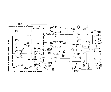
Referring to figure 1, a hydraulic circuit 100 is shown which includes a pair
of
tool lift and down pressure cylinders 112 connected in parallel by lines 114
and 116.
While two cylinders are shown, it will be understood that any number of
cylinders can
be used. The cylinders are used to raise and lower the tools as well as to
provide
automatically controlled down pressure to the associated tools, either
directly or
3
CA 02736297 2011-04-04
through a rockshaft (not shown). The hydraulic circuit 100 includes a pressure
reducing/relieving valve 118 which regulates the pressure delivered to the cap
end
120 of the cylinders 112. A tractor 122 includes a source of hydraulic fluid
under
pressure, a load sense controlled pump 130, connected through a tractor
selective
control valve (SCV) 132 to inputs 134 and 136 of the pressure
reducing/relieving
valve 118. The valve 118 further having an output 146 connected to the line
114.
The pump 130 provides flow to the SCV 132 which controls the extending and
retracting of the rods 124 of the cylinders 112. The SCV has four positions, a
neutral
position 132N, a tool lower position 132L, a tool raise position 132R and a
float
position 132F. A return check valve 138 allows flow to bypass the
reducing/relieving
valve 118 during cylinder retraction. A drain check valve 140 protects the
pressure
reducing/relieving valve 118 during cylinder retraction.
The active down force pressure load is communicated to the load sense
controlled pump 130 by load sense line 142. Fluid pressure for the active down
force
is provided through the fluid line 144 connecting the pump power beyond port
to the
input 134 of the pressure reducing/relieving valve 118. Two dual-pilot-
operated, two-
way, two-position, normally closed, directional valves 150 and 160 provide a
hydraulic latching function to the circuit. These valves may be combined into
one
dual-pilot-operated, four-way, two position valve. The directional valve 150
is
positioned in the fluid line 144 while the valve 160 is provided in the power
beyond
fluid return line 162. When the cylinders 112 are fully extended, the cap end
supply
pressure increases. This pressure pilots the directional valves 150, 160 open,
connecting the power beyond pressure to the pressure reducing/relieving valve
118
and the power beyond return port to the rod ends 126 of the cylinders. When
the
SCV 132 is returned to the neutral/closed position, the directional valves
150, 160
remain open. This allows the cylinders to extend and retract as the external
load on
the tools require and as the down force pressure allows.
4
CA 02736297 2011-04-04
When the SCV is actuated to retract the cylinders, the orifice 164 prevents a
free flow of the supply oil through the directional valve 160 to the power
beyond
return. This allows the pressure in the retract circuit to build enough
pressure to pilot
the directional valves 150, 160 closed. During cylinder retraction, the
cylinder extend
circuit is also connected to tank 128 which drops the opening pilot pressure
in the
directional valves 150, 160, allowing the spring and retract supply pilot
pressure to
close the directional valves 150, 160. When the SCV is moved to the float
position,
the directional valves 150, 160 pilot pressures equalize, allowing the springs
to close
the directional valves 150, 160, thus deactivating the down force circuit.
The above circuit, by adding the normally closed directional valve 150
prevents any pressure from building at the cylinder cap end during starting of
the
tractor 122. Thus there is no load communicated to the pump during starting of
the
tractor 122 that could possibly cause starting difficulties discussed above.
Furthermore, the circuit allows a load-sensed power source, the pump 130, to
be
activated and deactivated depending on the SCV position. The load-sensed power
source is activated when the cylinders are fully extended and remains
activated or
latched when the SCV is returned to neutral. It is deactivated or unlatched
when the
cylinders retracted.
An alternative circuit 200 is shown in figure 2. Here, elements similar or
identical to elements in the circuit 100 are given reference numbers beginning
with a
2 instead of a 1. Circuit 200 is similar to circuit 100 except the latching
function is
achieved by two single-pilot directional valves 250, 260 and an orifice 266
and a
pilot-to-open check valve 268 are added for optimizing the circuit. A load
sense
controlled pump 230 provides flow to SCV 232 which controls the extending and
retracting of cylinders 212. A pressure reducing/relieving valve 218 regulates
the
pressure delivered to the cap end 220 of the cylinders at all times. A return
check
valve 238 allows flow to bypass the pressure reducing/relieving valve 218
during
cylinder retraction. A drain check valve 240 protects the pressure
reducing/relieving
CA 02736297 2011-04-04
valve during cylinder retraction.
A pilot operated, two-way, two-position, normally open, directional valve 250
and a pilot operated, four-way, two-position, normally closed, directional
valve 260
provide the hydraulic latching function of the circuit. When the SCV extends
the
cylinders, oil flows freely through the pilot-to-open check valve 268 to the
pressure
reducing/relieving valve 218 and to the cap end of the cylinders. When the
cylinders
are fully extended, the cap end supply pressure increases. This pressure
pilots the
valve 260 open, connecting the power beyond pressure to the pressure
reducing/relieving valve 218 and the power beyond return port to the cylinder
retract
circuit. When the SCV is returned to the neutral/closed position, the
directional valves
250, 260, remain open, keeping the power beyond supply and return connected to
the cylinders 212. The orifice 266 prevents the pilot pressure to the
directional valve
260 from dropping too low during the SCV shift transition from the extend
position to
the neutral/closed position. This allows the cylinders to extend and retract
as the
external load on the tools require and as the down force pressure allows.
When the SCV is actuated to retract the cylinders, the orifice 264 prevents
free
flow of the supply oil through the directional valve 260 to the power beyond
return.
This allows the pressure in the retract circuit to build enough pilot pressure
to close
the directional valve 250. During cylinder retraction, the pilot-to-open check
valve 268
allows free return of oil around the orifice 266 to the SCV return port.
During cylinder
retraction, the extend circuit is also connected to tank 228 which drops in
the opening
pilot pressure in the directional valve 260 allowing it to close, thus un-
latching or
turning off the power beyond supply and return from the down force circuit.
When the
SCV is moved to the float position, the four-way, two-position, directional
valve 260
pilot pressure drops, allowing the valve to close. The orifice 266 can be used
to
prevent un-latching of the power beyond supply from the down force circuit
when the
SCV is in the float position. The orifice 266 and pilot-to-open check valve
268 may be
added to circuit 100 to keep the active down force circuit engaged when in
float.
6
CA 02736297 2011-04-04
With reference to figure 3, a third circuit 300 is shown. Circuit 300 is
similar to
circuit 200 except that the two-way, two-position, directional valve 250 of
circuit 200
has been replaced by a three-way, two-position directional valve 350. Further,
the
orifice 266 and pilot-to-open check valve 268 have been replaced by a check
valve
368. Lastly, the return check valve 338 has been routed around the directional
valve
360. These changes synchronize the un-latching of the power beyond supply
pressure with the cylinder 312 return oil during cylinder retraction.
It is a feature of the above hydraulic latching circuits that the regulated,
load-
sensed, power source is applied only when the cylinders have been extended,
i.e.,
the tools have been lowered. Furthermore, when the circuit is hydraulically
latched
on, active down force is maintained with the SCV in the neutral/closed
position.
Additionally, only regulated pressure is applied to the cylinders so the tools
are never
lowered with pressure greater than the desired down force pressure. Finally,
the
cylinders and down force functions can be operated without the use of power
beyond
and load sensing by using the SCV down detent as historically done. This is
useful
when tractors without power beyond are used with the above circuits.
While the invention has been described in the context of an implement active
down force system using cylinders connected to a rockshaft or directly
connected to
the implement tools, those skilled in the art will appreciate that the
invention can be
used in other applications involving use of a non-SCV controlled power beyond
circuit
in which latching of the circuit is desired by use of the SCV. The claims that
follow are
intended to be given this broad interpretation.
Having described the preferred embodiment, it will become apparent that
various modifications can be made without departing from the scope of the
invention
as defined in the accompanying claims.
7