Note : Les descriptions sont présentées dans la langue officielle dans laquelle elles ont été soumises.
CA 02736528 2014-02-06
Model-Predictive Online Identification of Patient Respiratory Effort
Dynamics in Medical Ventilators
BACKGROUND
Embodiments of the present invention generally relate to mechanical
ventilation,
and more particularly to systems and methods for improving synchrony between
patients
and ventilators by using a computationally efficient model-predictive approach
to
determining patient respiratory effort using a clinically-based internal model
of the patient
muscle pressure generator.
Modern ventilators are designed to ventilate a patient's lungs with gas, and
to
thereby assist the patient when the patient's ability to breathe on their own
is somehow
impaired. A ventilated patient system consists of the patient's respiratory
subsystem
controlled by highly complex neural centers and physiologic feedback
mechanisms, the
ventilator's dynamics and delivery algorithms, and the clinician-selected
(operator) settings
and protocols. Coordination and synchrony between the patient and ventilator
significantly
influence patient comfort, treatment effectiveness and homeostasis.
Consequently, systems
and methods for improving synchrony between patients and ventilators are
highly desirable.
SUMMARY
Systems and methods are described for efficient, continuous and online
computation of patient respiratory muscle effort. According to one embodiment,
there is
provided a method comprising: receiving, measuring, or estimating one or more
patient-
ventilator characteristics representing values of parameters of interest
associated with static
or dynamic properties or attributes of a ventilated patient system, the
ventilated patient
system including a respiratory subsystem of a patient and a ventilation
system, which
delivers a flow of gas to the patient; performing quantification of
respiratory muscle effort
of the patient by (i) establishing a respiratory predictive model of the
ventilated patient
system based on an equation of motion and one or more functions that
approximate
clinically-observed, patient-generated muscle pressures, (ii) determining an
instantaneous
1
CA 02736528 2014-02-06
leak flow value for the ventilated patient system, wherein the instantaneous
leak flow value
comprises an elastic leak orifice component and an inelastic leak orifice
component, and (iii)
based on the one or more patient-ventilator characteristics and the
instantaneous leak flow
value, solving the respiratory predictive model to extract an estimated
physiologic
respiratory muscle effort value; and configuring and operating the ventilation
system based
on the estimated physiologic respiratory muscle effort value or other
parameters derived
therefrom for monitoring or breath delivery purposes.
In the aforementioned embodiment, the functions may be periodic or semi-
periodic
functions having constant or time-varying amplitudes.
In various instances of the aforementioned embodiments, the functions that
approximate clinically-observed, patient-generated muscle pressures may
include a periodic
function for an inspiratory and expiratory phases of respiration that
approximates clinically-
observed, inspiratory muscle pressures and the estimated physiologic
respiratory muscle
pressure represents an estimate of inspiratory muscle effort generated by the
patient.
In the context of various of the aforementioned embodiments, an exemplary
periodic function for the inspiratory phase of respiration may be generally
expressed as:
(1¨ ¨t )sin (-7t1 )
Pmus,(t) = ¨P max
tv tv
where,
P max represents a maximum inspiratory muscle pressure, which may be a
constant or a time-varying parameter;
tv represents duration of inspiration; and
t represents an elapsed breath time varying between 0 and a total sum of
inspiration and expiration periods.
In various instances of the aforementioned embodiments, the functions that
approximate clinically-observed, patient-generated muscle pressures include a
periodic
function for the expiratory phase of respiration that approximates clinically-
observed,
expiratory muscle pressures and the estimated physiologic respiratory muscle
pressure value
represents an estimate of expiratory muscle effort generated by the patient.
2
CA 02736528 2011-03-08
WO 2010/036653 PCT/US2009/057867
In the aforementioned embodiment, an exemplary periodic function for the
expiratory phase of respiration may be generally expressed as:
t ,7r(t ¨A))
Pmuse(t) = ¨ sin (
tv hot ¨ 6
where,
P represents a maximum
expiratory muscle pressure, which may be a
constant or a time-varying parameter;
tv represents duration of expiration;
ttot represents a total sum of inspiration and expiration periods; and
t represents an elapsed breath time varying between 0 and trot.
In various instances of the aforementioned embodiments, the respiratory
predictive model is assumed to be valid for multiple breath cycles of the
patient and the
respiratory predictive model is periodically reestablished, updated or
optimized at
predetermined temporal windows during breath cycles of the patient.
In the context of various of the aforementioned embodiments, solving the
respiratory predictive model to extract an estimated physiologic respiratory
muscle
effort value involves solving the respiratory predictive model during a breath
cycle
subsequent to establishment of the respiratory predictive model and
compensating the
estimated physiologic respiratory muscle effort value for time delays
introduced by a
measurement system and indirect indication of muscular activity by surrogate
phenomena.
In the aforementioned embodiment, compensating the estimated physiologic
respiratory muscle effort value for time delays involves application of a
single-pole
dynamic compensation, an example of which may be generally expressed as:
WC"
Anus, dellver(s) = ____________ _1" mus(s)
S Z
where,
W represents a scaling factor incorporating a magnitude ratio of actual to
delivered muscle pressure;
3
CA 02736528 2014-02-06
r represents a delay time constant; and
z represents the single pole; and for the inspiration function
P max (5')2
Amic(s).-- (-7r) _ It
IV 2 ¨2 =
S2 +(tv
In the context of various of the aforementioned embodiments, solving the
respiratory
predictive model to extract a respiratory muscle effort value includes
optimizing derived
parameters of the equation of motion on an ongoing basis to tune to dynamics
of the ventilated
patient system.
In the aforementioned embodiment, the dynamics may include parameters
characterizing breathing mechanism and behavior of the patient.
Other embodiments of the present invention provide a ventilator system
comprising:
a ventilator-patient interface through which a flow of gas is delivered to a
patient; a patient
model estimator operable to receive measurements or estimates of one or more
patient-
ventilator characteristics of a ventilated patient system, the ventilated
patient system including
a respiratory subsystem of the patient and inspiratory and expiratory
accessories, the patient
model estimator adapted to perform quantification of respiratory muscle effort
of the patient by
(i) establishing a respiratory predictive model of the ventilated patient
system based on
an equation of motion and one or more periodic or semi-periodic functions that
approximate
clinically-observed, patient-generated muscle pressures, (ii) determining an
instantaneous leak
flow value for the ventilated patient system, wherein the instantaneous leak
flow value
comprises an elastic leak orifice component and an inelastic leak orifice
component, and (iii)
based on the received one or more measured or estimated characteristics and
the instantaneous
leak flow value, solving the respiratory predictive model to extract a
respiratory muscle effort
value; and a controller operable to control various aspects of delivery of the
flow of gas to the
patient based on the respiratory muscle effort value or one or more other
respiratory parameters
derived based on the respiratory muscle effort value.
4
CA 02736528 2011-03-08
WO 2010/036653
PCT/US2009/057867
In some instances of the aforementioned embodiment, the one or more periodic
or semi-periodic functions include a periodic or semi-periodic function that
approximates clinically-observed, inspiratory muscle pressures and the
respiratory
muscle pressure value represents an estimate of inspiratory muscle effort
generated by
the patient.
In various instances of the aforementioned embodiments, an exemplary
periodic function for the inspiratory phase of respiration may be generally
expressed as:
t 7rt
Pmust(() = ¨P max ( ¨ ¨ ) sm.(¨)
where,
P max represents a maximum inspiratory muscle pressure;
tv represents duration of inspiration; and
t represents an elapsed breath time varying between 0 and a total sum of
inspiration and expiration periods.
In the context of various of the aforementioned embodiments, the periodic or
semi-periodic functions include a periodic or semi-periodic function that
approximates
clinically-observed, expiratory muscle pressures and the respiratory muscle
pressure
value represents an estimate of expiratory muscle effort generated by the
patient.
In various instances of the aforementioned embodiments, an exemplary
periodic function for the expiration is generally expressed as:
, t ) , , , x (t¨tr))
Pmu ax se(t) P m ¨
tv trot ¨tv
where,
P max represents a maximum expiratory muscle pressure;
represents duration of expiration;
ttot represents a total sum of inspiration and expiration periods; and
t represents an elapsed breath time varying between 0 and ttot.
In some instances of the aforementioned embodiments, the respiratory
predictive model is assumed to be valid for multiple breath cycles of the
patient and the
5
CA 02736528 2014-02-06
respiratory predictive model is periodically reestablished, updated and/or
optimized at
predetermined temporal windows during breath cycles of the patient.
In the context of various of the aforementioned embodiments, solving the
respiratory predictive model to extract a respiratory muscle effort value
involves solving the
respiratory predictive model during a breath cycle subsequent to establishment
of the
respiratory predictive model and then correcting the respiratory muscle
pressure value to
account for time delays introduced by measurement and indirect indication of
muscular
activity by surrogate phenomena.
In some instances of the aforementioned embodiment, correcting the respiratory
muscle pressure value to account for time delays involves application of a
single-pole
dynamic generally expressed as:
We'r
F'mus,deliver(s) ______________ rmuc(s)
S Z
where,
W represents a scaling factor incorporating a magnitude ratio of actual to
delivered muscle pressure;
r represents a delay time constant; and
z represents the single pole; and for the expiration function
tv s 2 ++ 2s
P ¨ tv
pmus(s) = (7r max ) _ /tot )2
¨ 2
tv (t101 tv ) ¨
S + _______________________________________
tlof ¨ tv /
In some circumstances, solving the respiratory predictive model to extract a
respiratory muscle effort value involves optimizing derived parameters of the
equation of
motion.
This summary provides only a general outline of some embodiments of the
invention. Many other features, advantages and other embodiments of the
invention will
become more fully apparent from the following detailed description, the
appended claims
and the accompanying drawings.
6
CA 02736528 2011-03-08
WO 2010/036653
PCT/US2009/057867
BRIEF DESCRIPTION OF THE DRAWINGS
A further understanding of the various embodiments of the present invention
may be realized by reference to the figures which are described in remaining
portions of
the specification. In the figures, like reference numerals may be used
throughout several
of the figures to refer to similar components. In some instances, a sub-label
consisting
of a lower case letter is associated with a reference numeral to denote one of
multiple
similar components. When reference is made to a reference numeral without
specification to an existing sub-label, it is intended to refer to all such
multiple similar
components.
FIG. 1 depicts a simplified patient-ventilator modular block diagram in
accordance with an embodiment of the present invention.
FIG. 2 represents a simplified lumped-parameter analog model for a patient
circuit and a single-compartment respiratory system.
FIG. 3 depicts a patient model estimator in accordance with an embodiment of
the present invention.
FIG. 4 is a flow diagram illustrating ventilator control processing in
accordance
with an embodiment of the present invention.
FIG. 5 is a flow diagram illustrating continuous, online quantification of
respiratory muscle effort processing in accordance with an embodiment of the
present
invention.
FIG. 6 is a schematic depiction of a ventilator.
FIG. 7 schematically depicts control systems and methods that may be
employed with the ventilator of FIG. 6.
FIGs. 8A and 8B depict exemplary tidal breathing in a patient, and examples of
pressure/flow waveforms observed in a ventilator under pressure support with
and
without leak condition. Under leak condition, the inhalation flow is the total
delivered
flow including the leak flow and the exhalation flow is the output flow rate
measured by
the ventilator and excludes the exhaled flow exhausted through the leak.
7
CA 02736528 2011-03-08
WO 2010/036653
PCT/US2009/057867
FIGs. 9A and 9B depict an example embodiment of the patient interface shown
in Fig. 6.
FIG. 10 depicts an exemplary method for controlling the ventilator of FIG. 6,
including a method for compensating for leaks in ventilator components
according to an
embodiment.
8
CA 02736528 2014-02-06
DETAILED DESCRIPTION OF THE INVENTION
Systems and methods are described for efficient computation of patient
respiratory
muscle effort. As indicated above, in a ventilated patient system,
coordination and
synchrony between the patient and ventilator substantially influence patient
comfort,
treatment effectiveness and homeostasis. Embodiments of the present invention
seek to
improve synchrony between patients and ventilators by using a computationally
efficient
model-predictive approach to determining patient respiratory effort using a
clinically-based
internal model of the patient muscle pressure generator. In some embodiments,
the
respiratory predictive model includes one or more equations based on a
combination of the
equation of motion with a model of the inhalation phase or a model of the
exhalation phase
that are expressed as functions of one or more time parameters. In this
manner, after a
current respiratory predictive model is established that is valid for a number
of breath cycles,
subsequent evaluation of the model can be performed in a computationally
efficient manner
without the need to recalculate the entire model during each sampling
interval. In still other
embodiments, the computational model accuracy is further increased by
compensating for
leaks which may occur in the system or ventilation circuit. A variety of leak
estimation
techniques may be used within the scope of the present invention, including
the techniques
described in U.S. Patent Application Publication No. US2009/0241962, entitled
"Ventilator
Leak Compensation."
In the following description, for the purposes of explanation, numerous
specific
details are set forth in order to provide a thorough understanding of
embodiments of the
present invention. It will be apparent, however, to one skilled in the art
that embodiments of
the present invention may be practiced without some of these specific details
and/or other
embodiments may incorporate other details as necessary to realize the design
concept and
goals in specific platforms with specific characteristics.
Embodiments of the present invention may include various steps, which will be
described below. The steps may be performed by hardware components or may be
embodied
in machine-executable instructions, such as firmware or software, which may be
used to
cause a general-purpose or special-purpose processor programmed with the
9
CA 02736528 2011-03-08
WO 2010/036653
PCT/US2009/057867
instructions to perform the steps. Alternatively, the steps may be performed
and/or
facilitated by a combination of hardware, software, firmware and/or one or
more human
operators, such as a clinician.
Embodiments of the present invention may be provided as a computer program
product which may include a machine-readable medium having stored thereon
instructions which may be used to program a processor associated with a
ventilation
control system to perform various processing. The machine-readable medium may
include, but is not limited to, floppy diskettes, optical disks, compact disc
read-only
memories (CD-ROMs), and magneto-optical disks, ROMs, random access memories
(RAMs), erasable programmable read-only memories (EPROMs), electrically
erasable
programmable read-only memories (EEPROMs), magnetic or optical cards, flash
memory, MultiMedia Cards (MMCs), secure digital (SD) cards, such as miniSD and
microSD cards, or other type of media / machine-readable medium suitable for
storing
electronic instructions. Moreover, embodiments of the present invention may
also be
downloaded as a computer program product. The computer program may be
transferred
from a remote computer to a requesting computer by way of data signals
embodied in a
carrier wave or other propagation medium via a communication link (e.g., a
modem or
network connection). For example, various subsets of the functionality
described herein
may be provided within a legacy or upgradable ventilation system as a result
of
installation of a software option or performance of a firmware upgrade.
While, for convenience, various embodiments of the present invention may be
described with reference to a particular ventilation mode, such as PAY, the
present
invention is also applicable to various other ventilation modes, including,
but not limited
to Pressure Support, Pressure Control, Volume Control, BiLevel (volume-
controlled
pressure-regulated) and the like.
As used herein, the terms "connected" or "coupled" and related terms are used
in an operational sense and are not necessarily limited to a direct physical
connection or
coupling. Thus, for example, two devices of functional units may be coupled
directly, or
via one or more intermediary media or devices. As another example, devices or
functional units may be coupled in such a way that information can be passed
there
between, while not sharing any physical connection one with another. Based on
the
disclosure provided herein, one of ordinary skill in the art will appreciate a
variety of
CA 02736528 2011-03-08
WO 2010/036653
PCT/US2009/057867
ways in which connection or coupling exists in accordance with the
aforementioned
definition.
As used herein, the phrases "in one embodiment," "according to one
embodiment," and the like generally mean the particular feature, structure, or
characteristic following the phrase is included in at least one embodiment of
the
present invention, and may be included in more than one embodiment of the
present
invention. Importantly, such phases do not necessarily refer to the same
embodiment. If the specification states a component or feature "may", "can",
"could", or "might" be included or have a characteristic, that particular
component or
feature is not required to be included or have the characteristic.
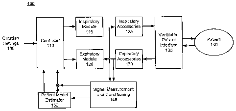
FIG. 1 depicts a simplified patient-ventilator modular block diagram in
accordance with an embodiment of the present invention. In the cutTent
example, the
major functional units / components of a patient-ventilator system 100 are
illustrated,
including an inspiratory module 115, an expiratory module 120, inspiratory
accessories
125, expiratory accessories 130, a ventilator-patient interface 135, a signal
measurement
and conditioning module 145, a patient model estimator 150, a controller 110
and a
patient 140.
The inspiratory module 115 may include a gas source, regulators and various
valving components. The expiratory module 120 typically includes an exhalation
valve
and a heated filter. The inspiratory accessories 125 and the expiratory
accessories 130
typically include gas delivery/exhaust circuits and other elements, such as
filters,
humidifiers and water traps.
Depending upon the particular type of ventilation (e.g., invasive ventilation
or
noninvasive ventilation), the ventilator-patient interface 135 may include
endotracheal
tubes or masks or others as appropriate for invasive or noninvasive use as
applicable.
Signal measurement and conditioning module 145 receives raw measurement
data from various sensors that may be part of the patient-ventilator system,
including but
not limited to physiological sensors, pressure sensors, flow sensors and the
like. The
signal measurement and conditioning module 145 may then manipulate various
signals
in such a way that they meet the requirements of the next stage for further
processing.
According to one embodiment, the signal measurement and conditioning module
145
11
CA 02736528 2011-03-08
WO 2010/036653
PCT/US2009/057867
may transform the raw sensor measurements into data in a form useable by the
patient
model estimator 150. For example, pressure and flow sensor data may be
digitized and
flow sensor data may be integrated to compute delivered volume.
Gas delivered to the patient 140 and/or expiratory gas flow returning from the
patient 140 to the ventilation system may be measured by one or more flow
sensors (not
shown). A flow sensor may comprise any sensor known in the art that is capable
of
determining the flow of gas passing through or by the sensor. In some
particular
embodiments of the present invention, the flow sensors may include a proximal
flow
sensor as is known in the art, In one embodiment, the flow sensors include two
separate
and independent flow sensors, a first sensor configured to meter a flow of
breathing gas
delivered to the patient 140 from the ventilation system and a second sensor
configured
to meter expiratory gas flow returning from the patient 140 to the ventilation
system.
According to one embodiment of the present invention, the one or more flow
sensors may comprise a single flow sensor positioned at a port defining an
entry to an
airway of the patient 140. In such an embodiment, the single flow sensor may
be
configured to meter both a flow of breathing gas delivered to the patient 140
by the
ventilation system and a flow of gas returning from the patient 140 to the
ventilation
system. In one embodiment, a single flow sensor may be located at a connector
(e.g.,
the patient wye) that joins the inspiratory and expiratory limbs of a two-limb
patient
circuit to the patient airway. Based on the disclosure provided herein, one of
ordinary
skill in the art will recognize a variety of different types of flow sensors
that may be
used in relation to different embodiments of the present invention.
During inhalation, the controller 110 commands actuators in the inspiratory
module to regulate gas delivery (e.g., flow and oxygen mix) through the
ventilator-
patient interface 135 responsive to parameter values of a respiratory
predictive model
continuously evaluated by the patient model estimator 150. For example, in the
context
of a Proportional Assist Ventilation (PAY) mode, the controller 110 regulates
gas
delivery such that proximal airway pressure tracks a desired airway trajectory
that may
be periodically computed based on patient-generated muscle pressure using
patient
respiratory parameters, instantaneous inspiratory lung flow and clinician
settings 105,
such as a clinician-set support level. Further description regarding the
patient model
estimator 150 is provided below.
12
CA 02736528 2011-03-08
WO 2010/036653
PCT/US2009/057867
In one embodiment, the functionality of one or more of the above-referenced
functional units may be merged in various combinations. For example, patient
model
estimator 150 and controller 110 or signal measurement and conditioning module
145
and patient model estimator 150 may be combined. Moreover, the various
functional
units can be communicatively coupled using any suitable communication method
(e.g.,
message passing, parameter passing, and/or signals through one or more
communication
paths, etc.). Additionally, the functional units can be physically connected
according to
any suitable interconnection architecture (e.g., fully connected, hypercube,
etc.).
According to embodiments of the invention, the functional units can be any
suitable type of logic (e.g., digital logic, software code and the like) for
executing the
operations described herein. Any of the functional units used in conjunction
with
embodiments of the invention can include machine-readable media including
instructions for performing operations described herein. Machine-readable
media
include any mechanism that provides (i.e., stores and/or transmits)
information in a form
readable by a machine (e.g,, a computer). For example, a machine-readable
medium
includes, but is not limited to, read only memory (ROM), random access memory
(RAM), magnetic disk storage media, optical storage media or flash memory
devices.
FIG. 2 represents a simplified lumped-parameter analog model for a patient
circuit and a single-compartment respiratory system. The model 200 includes a
ventilator 205, resistance, Rt 210, representing circuit tubing resistance,
compliance, Ct
235, representing circuit tubing compliance, and resistance, RI 230,
representing leak
resistance. In the context of this model 200, respiratory dynamics are
captured by total
respiratory resistance, Rp 240, total respiratory compliance, Cp 250, and
patient-
generated muscle pressure, Prns 255.
For practical purposes, the magnitude of the negative pressure generated by
the
inspiratory muscles, Pm us 255, is used as an index of breathing effort.
Airway pressure,
Paw 220, measured at the ventilator-patient interface, e.g., ventilator-
patient interface
135, may be calculated on an ongoing basis using patient parameters and Pmõ,
255
according to the equation of motion:
P(t) = Ep SQpdt QpRp ¨ Pnms(t) EQ #1
where,
13
CA 02736528 2011-03-08
WO 2010/036653
PCT/US2009/057867
Qp = Qin ¨ Qnlit + phase* a EQ #2
Qp 245 is the instantaneous patient flow, and Ep and Rp are the patient's
respiratory elastance and resistance, respectively. Qin represents the total
flow delivered
to the patient wye by the ventilator. Qõt is the total flow estimated at the
patient wye
and exhausted through the exhalation limb. Qiis the instantaneous leak flow.
Phase is -
1 during inspiration and +1 during exhalation. Inspiratory muscle pressure is
negative
with a magnitude of Põ,,,, 255. Patient (lung) flow is assumed positive during
inhalation
and negative during exhalation.
Constructing an accurate and predictive model of the patient muscle pressure
generator is challenging. Inspiratory muscle pressure, Põms 255, is a time-
variant
excitation function with inter- and intra-subject variations. In normal
subjects, it is
believed that Pmus is in general dependent on breath rate, inspiration time
and
characteristic metrics of the inspiratory pressure waveform. However, in
patients, other
factors related to demanded and expendable muscle energy may critically
influence
muscle pressure generation. For example, for a given peak inspiratory
pressure, the
maximum sustainable muscle pressure may be affected by factors impairing
muscle
blood flow (blood pressure, vasomotor tone, muscle tension in the off-phase),
the
oxygen content of perfusing blood (P02, hemoglobin concentration), blood
substrate
concentration (glucose, free fatty acids), and the ability to extract sources
of energy from
the blood. Thus, respiratory motor output may vary significantly in response
to
variations in metabolic rate, chemical stimuli, temperature, mechanical load,
sleep state
and behavioral inputs. Moreover, there is a breath-by-breath variability in
respiratory
output that could lead to tidal volumes varying by a factor of four or more.
The
mechanism of this variability is not yet known.
According to various embodiments of the present invention, functions that
approximate actual clinically-observed inspiratory and expiratory muscle
pressures are
used as part of a respiratory predictive model by substituting them into the
equation of
motion (EQ #1) as appropriate. An example of a periodic function meeting these
criteria
for the inhalation phase is the following:
t . ,7rt
P11(t) ¨P MIõX ( I ) sin( , EQ #3
tv tv
14
CA 02736528 2011-03-08
WO 2010/036653
PCT/US2009/057867
where,
represents a maximum inspiratory pressure,
tv represents duration of inspiration;
t represents an elapsed breath time varying between 0 and a total sum of
inspiration and expiration periods; and
Muscle pressure, Põõõ represents the magnitude of Pn..
Based on the disclosure provided herein, one of ordinary skill in the art will
recognize a variety of alternative periodic and semi-periodic functions that
may be used
in relation to different embodiments of the present invention. For example, in
EQ #3,
above, P.a. may be assumed to be a constant or a time-varying parameter, thus
resulting in a function having a constant amplitude or a time-varying
amplitude.
A similar model may be used for the exhalation phase as well. An example of
a periodic function meeting the criteria of approximating actual clinically-
observed
expiratory muscle pressures is the following:
õ E. ¨6) )
Pm.,(t) P max( t ¨)sin( _________________________________________________ EQ
#4
tr trot ¨ Iv
where,
P max represents a maximum expiratory pressure,
represents duration of expiration;
ttot represents a total sum of inspiration and expiration periods;
t represents an elapsed breath time varying between 0 and ttot; and
Muscle pressure, Põ,õ represents the magnitude of P.
Based on the disclosure provided herein, one of ordinary skill in the art will
recognize a variety of alternative periodic and semi-periodic functions that
may be used
in relation to different embodiments of the present invention. For example, in
EQ #4,
above, P .ax may be assumed to be a constant or a time-varying parameter, thus
resulting in a function having a constant amplitude or a time-varying
amplitude.
In alternative embodiments, inspiratory and expiratory resistances used in the
respiratory predictive model may be assumed to be equal.
CA 02736528 2011-03-08
WO 2010/036653
PCT/US2009/057867
While, as discussed above, under real conditions, Pm, and t are known to
demonstrate time-variance, for purposes of various embodiments of the present
invention, Pmax is assumed to be constant for fixed steady state conditions of
physiologic
and interactive parameters affecting muscle pressure generation. During
inspiration, the
magnitude of Rp and Cp change dynamically as the lung is inflated.
Taking the Laplace transform of Pmõ, during inspiration to produce a more
readily and computationally efficiently solvable algebraic equation yields the
following:
Pmax
(s 71. )2
Pima()) = (g) tv tr EQ
#5
¨ 2
[S2 +1¨ )2
tv
A similar function may be derived for the exhalation phase using EQ #4,
above.
In accordance with various embodiments of the present invention, combining the
inhalation and exhalation models above with the equation of motion in terms of
patient
and ventilator/accessories parameters to form a respiratory predictive model,
a model-
predictive online identification approach is devised to extract Qi (via a leak
detection
and characterization algorithm discussed further below), Pniax and optionally
Rp as well
as C.
According to one embodiment, the model-predictive online identification
approach involves continuous and breath-by-breath online evaluation and
adaptive
parameter optimization of the parameters of the equation of motion across the
whole
breath cycle as well as a number of defined temporal windows during inhalation
and
active and passive exhalation to constitute a sufficient number of equations
to solve for
the number of unknowns of interest and/or adequate to optimize one or more
derived
parameters.
FIG. 3 depicts a patient model estimator 350 in accordance with an
embodiment of the present invention that is capable of receiving information
and/or
parameters regarding various sensor measurements 315, using a computationally
efficient model-predictive approach to determining patient respiratory effort
using a
clinically-based internal model of the patient muscle pressure generator, and
providing
16
CA 02736528 2011-03-08
WO 2010/036653
PCT/US2009/057867
information regarding estimated physiologic patient respiratory effort 330 to
a
controller, such as controller 110.
According to the present example, patient model estimator 350 includes a
processor 305, a memory 310, operational instructions 320 stored within the
memory
310 and a controller interface 325.
Processor 305 may be any processor known in the art that is capable of
receiving and processing sensor measurements 315, executing various
operational
instruction 320 maintained in the memory 310, receiving, measuring and/or
estimating
patient-ventilator characteristics 335, performing continuous, online
quantification of
respiratory muscle effort of the patient and otherwise interacting with
various other
functional units of the ventilator system, such as controller 110 via the
controller
interface 325. In one embodiment of the present invention, processor 330 may
receive
interrupts on a periodic basis to trigger ventilator configuration and/or
control processing
activities. Such interrupts may be received, for example, every 5
milliseconds.
Alternatively, the interrupts may be received whenever the validity of various
parameter
values or the validity of the respiratory predictive model is determined to
have expired.
Furthermore, interrupts may be received upon availability of sensor
measurements 315.
Such interrupts may be received using any interrupt scheme known in the art
including,
but not limited to, using a polling scheme where processor 330 periodically
reviews an
interrupt register, or using an asynchronous interrupt port of processor 330.
Alternatively or additionally, the processor 330 may proactively request
sensor
measurements 315 be provided from the signal measurement and conditioning
module
145 and/or measurements or user input be provided regarding patient-ventilator
characteristics 335 on a periodic or as needed basis. Based on the disclosure
provided
herein, one of ordinary skill in the art will recognize a variety of interrupt
and/or polling
mechanisms that may be used in relation to different embodiments of the
present
invention.
In one embodiment of the present invention, processor 330 performs
continuous, online quantification of respiratory muscle effort of a patient
with reference
to a respiratory predictive model of the ventilated patient system as
discussed in further
detail below. At a high-level, the computationally efficient model-predictive
approach
to determining patient respiratory effort in accordance with one embodiment of
the
17
CA 02736528 2011-03-08
WO 2010/036653
PCT/US2009/057867
present invention is generally described as follows. The processor 305
receives operator
input indicative of, receives measurements indicative of, or estimates, one or
more
patient-ventilator characteristics 335. The patient-ventilator characteristics
335
represent values of parameters of interest associated with static or dynamic
properties or
attributes of the ventilated patient system.
Based on the patient-ventilator characteristics 335 and sensor measurements
315, the processor 305 continuously performs online (i.e., during ventilator
operation),
quantification of respiratory muscle effort of the patient. Initially, the
processor 305
establishes a respiratory predictive model of the ventilated patient system
based on the
equation of motion and one or more functions that approximate clinically-
observed,
patient-generated muscle pressures. The respiratory predictive model may be
reestablished, updated and/or optimized as described further below.
At each of a predetermined set of computational stages, system leak is
characterized and quantified such that a reliable instantaneous leak flow
value for the
ventilated patient system may be computed. Then, calculations are performed to
estimate and/or optimize the rest of the parameters, including one or more of
P., Rp
and C. According to one embodiment, the respiratory predictive model is
assumed to
be valid for multiple breath cycles thereby allowing a model established,
updated and/or
optimized during one breath cycle to be solved during the same breath cycle or
a
subsequent breath cycle to extract one or more patient parameters by simply
substituting
into the current respiratory predictive model (i) received, estimated and/or
measured
patient-ventilator characteristics 335, (ii) available sensor measurements
315, and (iii)
one or more time values, such as the duration of inspiration or expiration, an
elapsed
breath time and a total sum of inspiration and expiration periods.
In various embodiments, an estimated physiologic respiratory muscle effort
value extracted from the model may be compensated for time delays introduced
by the
ventilator's measurement system and/or the indirect indication of muscular
activity by
surrogate phenomena (e.g., pressure) by applying a single-pole dynamic
described
further below.
Finally, information regarding the estimated physiologic patient effort 330
may
be provided to the controller 110 via the controller interface 325, thereby
configuring
18
CA 02736528 2011-03-08
WO 2010/036653
PCT/US2009/057867
and operating the ventilation system based on the estimated physiologic
patient effort
330 or other parameters derived there from for monitoring or breath delivery
purposes.
Memory 310 includes operational instructions 320 that may be software
instructions, firmware instructions or some combination thereof. Operational
instructions 320 are executable by processor 305, and may be used to cause
processor
305 to deliver information, such as estimated physiologic patient respiratory
effort 330
via controller interface 325 to controller 110, which responsive thereto may
then control,
configure and/or operate the ventilator in a programmed manner based directly
or
indirectly upon the estimated physiologic patient respiratory effort 330.
FIG. 4 is a flow diagram illustrating ventilator control processing in
accordance
with an embodiment of the present invention. According to the present example,
an
interrupt mechanism and/or polling loop that may be used in accordance with an
embodiment of the present invention to initiate patient model estimation and
ventilator
control processing. In the present example, it is assumed that the interrupt
or polling
cycle occurs more frequently than a predetermined or configurable parameter
measurement/estimation period.
At decision block 410, a determination is made regarding whether the
parameter measurement/estimation period has elapsed. If so, then processing
continues
with block 420; otherwise, processing branches back to decision block 410.
At block 420, depending upon the sensors and data available in the ventilated
patient system, measurements and/or estimates of those system parameters
capable of
being measured or estimated and which are of relevance to patient model
estimation are
performed. For example, if flow sensors are available in the ventilated
patient system,
then Qin and/or Qt may be provided to the patient model estimation process.
Alternatively or additionally, operator provided inputs regarding one or more
system
parameters may be collected for purposes of facilitating the patient model
estimation
process.
At block 430, an online patient model estimation process is performed to
determine an estimated physiologic patient respiratory effort value and
potentially other
parameters, such as Rp and C. As will be described further below with
reference to
FIG. 5, in one embodiment, the patient model estimation process may involve
19
CA 02736528 2011-03-08
WO 2010/036653
PCT/US2009/057867
establishment, reestablishment, updating and/or optimization of a respiratory
predictive
model valid for multiple breath cycles based upon a combination of the
equation of
motion with functions that substantially approximate clinically-observed,
patient-
generated muscle pressures. Further details regarding the patient model
estimation
process are provided below. At this point in the discussion, it is sufficient
to simply note
that outputs of the patient model estimation process include one or more
parameters,
e.g., Qi, Pm, Rp and Cp, extracted fi.om the current respiratory predictive
model that
may be used to directly or indirectly configure operation of the ventilation
system.
At block 440, the ventilation system is configured based on the estimated
physiologic patient respiratory effort value, other parameters derived or
estimated based
on the patient model estimation process and/or other respiratory parameters
derived
based on the estimated physiologic patient respiratory effort value. According
to one
embodiment, configuration of the ventilation system is accomplished indirectly
by the
patient model estimator 150 providing one or more outputs of its processing to
the
controller 110. Controller 110 may then use the one or more parameters
provided by
patient model estimator 150 to start or stop or regulate a ventilator assisted
/ supported
breath phase or ventilatory parameter, such as to determine an appropriate
pressure for a
PAY mode, for example.
FIG. 5 is a flow diagram illustrating online quantification of respiratory
muscle
effort processing that may be performed in a continuous manner in accordance
with an
embodiment of the present invention. According to the current example, a
patient model
estimation process is periodically performed responsive to an interrupt
mechanism
and/or polling loop.
At decision block 510, it is determined whether the current time offset into
the
breath cycle corresponds to a predefined temporal window during the breath
cycle. If
so, then processing continues with block 520; otherwise, processing branches
to block
530. Examples of predefined temporal windows include, but are not limited to,
(i) times
during a breath cycle in which characteristics of the breath waveform are
known; (ii)
times at which sufficiently definite information is available regarding one or
more
patient or system parameters, (iii) predefined or configurable intervals
within a breath
cycle (e.g., X times per breath cycle), (iv) times at which sufficiently
definite
information is available regarding one or more patient parameters or
characteristics of
CA 02736528 2011-03-08
WO 2010/036653
PCT/US2009/057867
breathing behavior based on physiologic knowledge of respiration mechanism
and/or
expected or reasonable deductions derived from operator inputs and settings
and the like.
Alternatively, the respiratory predictive model may be reestablished, updated
and/or
optimized responsive to observing Or being informed of changes in patient
behavior or
patient lung characteristics. The respiratory predictive model may also be
reestablished
or updated responsive to an error threshold being exceeded or observing or
being
informed of the fact that one or more patient and/or system parameters derived
based on
the current respiratory predictive model fall outside of an expected range or
otherwise
exhibit indicators of inaccuracy.
At block 520, a respiratory predictive model of the ventilated patient system
is
established, reestablished, updated and/or optimized. According to one
embodiment, the
respiratory predictive model is one or more equations based on a combination
of the
equation of motion with a model of the inhalation phase or a model of the
exhalation
phase that are expressed as functions of one or more time parameters (e.g., t,
t and/or
4,0. Advantageously, in this manner, after a current respiratory predictive
model is
established that is valid for a number of breath cycles, subsequent evaluation
of the
model can be performed in a computationally efficient manner without the need
to
recalculate the entire model during each sampling interval.
At block 530, the instantaneous leak flow, Qi, for the ventilated patient
system
is determined. Various methods may be used. According to one embodiment the
instantaneous leak flow is determined as described further below with
reference to FIGs.
6-10.
At block 540, the current respiratory predictive model is solved based on the
available / known parameters and based on the current time offset into the
current breath
to extract an estimated physiologic respiratory muscle pressure value and/or
other
desired parameters, such as Rp and C.
Depending upon the particular ventilator platform, various other approaches to
solving the equation of motion in the context of the respiratory predictive
model
described herein may be used. For example, Rp and Cp may first be calculated
and then
P extracted. Alternatively, the respiratory predictive model may be solved
during
multiple successive sampling intervals or specified temporal windows and the
error can
be minimized to find the best values. In other approaches, the respiratory
predictive
21
CA 02736528 2011-03-08
WO 2010/036653
PCT/US2009/057867
model may be solved during particular windows of time during a breath cycle in
which
characteristics of the breath waveform are known and can therefore be used to
verify the
extracted parameters.
There are multitude of approaches for identification and estimation of the
parameters of the patient-ventilator model (e.g., Rp, Cp, Pp., etc.).
Selection of an
approach is dependent on the characteristics of the operating platform
(ventilator
system) and performance requirements as well as computational costs. In
general, the
physical equations governing the dynamical functioning and performance of the
system
(for example, equation of motion) as well as conservation laws such as mass
and volume
balance over cyclical respiratory intervals (e.g., one complete breath period)
may be
used to determine the unknown parameters of interest. In addition, the closed-
loop
nature of ventilatory functions, namely, feedback control and maintenance of
pre-set
pressure and/or flow trajectories with known expected characteristics (e.g.,
constant
slope), may be used to generate additional equations and mathematical
relationships.
Furthermore, such equations and mathematical relationships may be applied
under
appropriately conditioned temporal windows in conjunction with expected
dynamics of
the respiration function to solve for or retune or optimize parameters on
interest.
In one embodiment, estimates of Rp, Cp may be available (provided by the
operator) or derived during ventilation using protocols and algorithms for
respiratory
maneuvers and procedures (e.g., controlled test breaths) to determine and tune
respiratory mechanics (Rp, Cp, etc.). The estimated values for Rp, Cp may then
be used in
the equation of motion and applied at one or several points during inhalation
and
exhalation to determine an optimum estimate of the corresponding Pm.
In other embodiments, after a feasible approach for the platform and
application of interest is selected, a set of equations may be determined to
be applied
using a cost effective methodology for online parameter estimation and
optimization
(e.g., methods and algorithms for closed-loop identification, neural networks
and
neurodynamic programming, adaptive parameter estimation, etc.). Following an
appropriate online estimation of choice selected specifically to satisfy the
design needs
of specific projects, one or more model parameters (Rp, Cp, P.m) may be
estimated and
regularly updated as need be.
22
CA 02736528 2011-03-08
WO 2010/036653
PCT/US2009/057867
FIG. 6 depicts a ventilator 620 according to the present description. As will
be
described in detail, the various ventilator system and method embodiments
described
herein may be provided with control schemes that provide improved leak
estimation
and/or compensation. These control schemes typically model leaks based upon
factors
that are not accounted for in prior ventilators, such as elastic properties
and/or size
variations of leak-susceptible components. The present discussion will focus
on specific
example embodiments, though it should be appreciated that the present systems
and
methods are applicable to a wide variety of ventilator devices.
Referring now specifically to FIG. 6, ventilator 620 includes a pneumatic
system 622 for circulating breathing gases to and from patient 624 via airway
626,
which couples the patient to the pneumatic system via physical patient
interface 628 and
breathing circuit 630. Breathing circuit 630 could be a two-limb or one-limb
circuit for
carrying gas to and from the patient. A wye fitting 636 may be provided as
shown to
couple the patient interface to the breathing circuit.
The present systems and methods have proved particularly advantageous in
non-invasive settings, such as with facial breathing masks, as those settings
typically are
more susceptible to leaks. However, leaks do occur in a variety of settings,
and the
present description contemplates that the patient interface may be invasive or
non-
invasive, and of any configuration suitable for communicating a flow of
breathing gas
from the patient circuit to an airway of the patient. Examples of suitable
patient interface
devices include a nasal mask, nasal/oral mask (which is shown in FIG. 6),
nasal prong,
full-face mask, tracheal tube, endotracheal tube, nasal pillow, etc.
Pneumatic system 622 may be configured in a variety of ways. In the present
example, system 622 includes an expiratory module 640 coupled with an
expiratory limb
634 and an inspiratory module 642 coupled with an inspiratory limb 632.
Compressor
644 is coupled with inspiratory module 642 to provide a gas source for
ventilatory
support via inspiratory limb 632.
The pneumatic system may include a variety of other components, including
sources for pressurized air and/or oxygen, mixing modules, valves, sensors,
tubing,
accumulators, filters, etc. Controller 650 is operatively coupled with
pneumatic system
622, signal measurement and acquisition systems, and an operator interface 652
may be
provided to enable an operator to interact with the ventilator (e.g., change
ventilator
23
CA 02736528 2011-03-08
WO 2010/036653
PCT/US2009/057867
settings, select operational modes, view monitored parameters, etc.).
Controller 650
may include memory 654, one or more processors 656, storage 658, and/or other
components of the type commonly found in command and control computing
devices.
As described in more detail below, controller 650 issues commands to pneumatic
system
622 in order to control the breathing assistance provided to the patient by
the ventilator.
The specific commands may be based on inputs received from patient 624,
pneumatic
system 622 and sensors, operator interface 652 and/or other components of the
ventilator. In the depicted example, operator interface includes a display 659
that is
touch-sensitive, enabling the display to serve both as an input and output
device.
FIG. 7 schematically depicts exemplary systems and methods of ventilator
control. As shown, controller 650 issues control commands 760 to drive
pneumatic
system 722 and thereby circulate breathing gas to and from patient 624. The
depicted
schematic interaction between pneumatic system 722 and patient 624 may be
viewed in
terms of pressure and/or flow "signals." For example, signal 762 may be an
increased
pressure which is applied to the patient via inspiratory limb 632. Control
commands 760
are based upon inputs received at controller 650 which may include, among
other things,
inputs from operator interface 652, and feedback from pneumatic system 722
(e.g., from
pressure/flow sensors) and/or sensed from patient 624.
In many cases, it may be desirable to establish a baseline pressure and/or
flow
trajectory for a given respiratory therapy session. The volume of breathing
gas delivered
to the patient's lung and the volume of the gas exhaled by the patient are
measured or
determined, and the measured or predicted/estimated leaks are accounted for to
ensure
accurate delivery and data reporting and monitoring. Accordingly, the more
accurate the
leak estimation, the better the baseline calculation of delivered and exhaled
volume as
well as event detection (triggering and cycling phase transitions).
FIGs. 7, 8A and 8B may be used to illustrate and understand leak effects and
errors. As discussed above, therapy goals may include generating a desired
time-
controlled pressure within the lungs of patient 624, and in patient-triggered
and -cycled
modes, achieve a high level of patient-device synchrony.
FIG. 8A shows several cycles of flow/pressure waveforms spontaneous
breathing under Pressure Support mode with and without leak condition. As
discussed
24
CA 02736528 2011-03-08
WO 2010/036653
PCT/US2009/057867
above, a patient may have difficulty achieving normal tidal breathing, due to
illness or
other factors.
Regardless of the particular cause or nature of the underlying condition,
ventilator 620 typically provides breathing assistance during inspiration and
exhalation.
FIG. 8B shows an example of flow waveform under Pressure Support in presence
of no
leak as well as leak conditions. During inspiration more flow is required
(depending on
the leak size and circuit pressure) to achieve the same pressure level
compared to no leak
condition. During exhalation, a portion of the volume exhaled by the patient
would exit
through the leak and be missed by the ventilator exhalation flow measurement
subsystem. In many cases, the goal of the control system is to deliver a
controlled
pressure or flow profile or trajectory (e.g., pressure or flow as a function
of time) during
the inspiratory phases of the breathing cycle. In other words, control is
performed to
achieve a desired time-varying pressure or flow output 762 from pneumatic
system 722,
with an eye toward causing or aiding the desired tidal breathing shown in FIG.
8A.
Improper leak accounting can compromise the timing and magnitude of the
control signals applied from controller 650 to pneumatic system 722 especially
during
volume delivery. Also, lack or inaccurate leak compensation can jeopardize
spirometry
and patient data monitoring and reporting calculations. As shown at schematic
leak
source LI, the pressure applied from the pneumatic system 722 to patient
interface 628
may cause leakage of breathing gas to atmosphere. This leakage to atmosphere
may
occur, for example, at some point on inspiratory limb 632 or expiratory limb
634, or at
where breathing circuit 630 couples to patient interface 628 or pneumatic
system 722.
In the case of non-invasive ventilation, it is typical for some amount of
breathing gas to escape via the opening defined between the patient interface
(e.g., facial
breathing mask) and the surface of the patient's face. In facial masks, this
opening can
occur at a variety of locations around the edge of the mask, and the size and
deformability of the mask can create significant leak variations. As one
example, as
shown in FIG. 9A and FIG. 9B, the facial breathing mask may be formed of a
deformable plastic material with elastic characteristics. Under varying
pressures, during
inspiration and expiration the mask may deform, altering the size of the leak
orifice 961.
Furthermore, the patient may shift (e.g., talk or otherwise move facial
muscles), altering
the size of leak orifice 961. Due to the elastic nature of the mask and the
movement of
CA 02736528 2014-02-06
the patient, a leak compensation strategy assuming a constant size leak
orifice may be
inadequate.
Accurately accounting for the magnitude of leak Li may provide significant
advantages. In order for controller 650 to command pneumatic system 722 to
deliver the
desired amount of volume/pressure to the patient at the desired time and
measure/estimate the
accurate amount of gas volume exhaled by the patient, the controller must have
knowledge of
how large leak Li is during operation of the ventilator. The fact that the
leak magnitude
changes dynamically during operation of the ventilator introduces additional
complexity to the
problem of leak modeling.
Triggering and cycling (patient-ventilator) synchrony may also be compromised
by
sub-optimal leak estimation. In devices with patient-triggered and patient-
cycled modalities
that support spontaneous breathing efforts by the patient, it can be important
to accurately
detect when the patient wishes to inhale and exhale. Detection commonly occurs
by using
accurate pressure and/or lung flow (flow rates into or out of the patient
lung) variations. Leak
source L2 represents a leak in the airway that causes an error in the signals
to the sensors of
pneumatic system 722. This error may impede the ability of ventilator to
detect the start of an
inspiratory effort, which in turn compromises the ability of controller 650 to
drive the
pneumatic system in a fashion that is synchronous with the patient's
spontaneous breathing
cycles.
In some embodiments, leak estimation is included when quantifying the patient
respiratory muscle effort and/or when controlling the delivery of gas to the
patient. While a
variety of leak estimation and leak calculation techniques may be used within
the scope of the
present invention, in some embodiments leak calculation is performed in a
manner similar to
that described in U.S. Patent Application Publication No. US2009/0241962.
Improved leak
estimation may be achieved in the present examples through provision of a
control scheme that
more fully accounts for factors affecting the time-varying magnitude of leaks
under interface
and airway pressure variations. The present example may include, in part, a
constant-size leak
model consisting of a single parameter (orifice resistance, leak conductance,
or leak factor)
utilized in conjunction with the pneumatic flow equation through a rigid
orifice, namely,
26
CA 02736528 2011-03-08
WO 2010/036653
PCT/US2009/057867
Qleak = (leak factor/Resistance/Conductance)* VAP EQ #6
Where AP =pressure differential across the leak site. This assumes a fixed
size leak (i.e., a constant leak resistance or conductance or factor over at
least one breath
period).
To provide a more accurate estimate of instantaneous leak, the leak detection
system and method may also take into account the elastic properties of one or
more
components of the ventilator device (e.g., the face mask, tubing used in the
breathing
circuit, etc.). This more accurate leak accounting enhances patient-ventilator
synchrony
and effectiveness under time-varying airway pressure conditions in the
presence of both
rigid orifice constant size leaks as well as pressure-dependent varying-size
elastic leak
sources.
According to the pneumatic equations governing the flow across an orifice, the
flow rate is a function of the area and square root of the pressure difference
across the
orifice as well as gas properties. For derivation of the algorithm carried out
by the
controller, constant gas properties are assumed and a combination of leak
sources
comprising of rigid fixed-size orifices ( total area = A,. = constant) and
elastic opening
through the patient interface [ total area = yle (P)= function of applied
pressure].
Therefore,
Qlõk = Ko * (4. + 4(P))* !AP EQ #7
K, = assumed constant
For the purposes of this implementation, at low pressure differences, the
maximum center deflection for elastic membranes and thin plates are a quasi-
linear
function of applied pressure as well as dependent on other factors such as
radius,
thickness, stress, Young's Modulus of Elasticity, Poisson's Ratio, etc.
Therefore,
4(13) = K ,* AP EQ #8
K, = assumed constant
27
CA 02736528 2011-03-08
WO 2010/036653
PCT/US2009/057867
As AP is the pressure difference across a leak source to ambient (P = ),
then we substitute AP by the instantaneous applied pressure PO and rearrange
EQ #6 as
follows (K1 and K2 areassumed to be constant):
Qleak = Ko(A, KeP(0)V AP EQ #9
Qteak *p(o1/2 + K2 *p(03/2 EQ
#10
Also, the total volume loss over one breath period = 1",
leak Delivered Volume
¨ Exhausted Volume;
Tb TT)
Vieak = f[K1P(t)1/2 K2P(t)312 }di = Qdellvcred
¨Qexii]* dt EQ
0 0
#11
Tb= full breath period
The general equation of motion for a patient ventilator system during passive
exhalation can then be written,
Paw + Pm = R*(Qienk Qexli alelivereci) (11 C)* [Qiõk Qe:ch delivered]* dt
EQ #12
Paw = airway pressure
= muscle pressure
R = resistance
C = Compliance
Assuming that when end exhalation conditions are present a constant airway
pressure is being delivered (steady PEEP), constant bias flow maintained
during
exhalation phase 0
constant leak flow (due to no pressure variation), and Pm =0
(due to no patient respiratory effort), the equation of motion could be
differentiated and
reorganized as follows:
dP" =0 = R*Qõhdot +eak Q-
Qdebvered EQ
dt
#13
28
CA 02736528 2011-03-08
WO 2010/036653
PCT/US2009/057867
Q leak = (Qdelivered Qui)) R*C*Qdot EQ
#14
Qexhdot = time derivative of exhausted flow
If Qe.thdot = 0, EQ #13 can be reduced to
Q leak = Qdelivered Quit EQ
#15
And subsequently,
Qiõ/, = Kt (PEEP)1 K2(PEEP)312 EQ
#16
Otherwise ashclot # 0. In this case, an appropriate duration of time AT is
taken
during passive exhalation period and assuming constant delivered flow,
equation can be
derived as follows:
(Q (t + AT)¨Qe.th(t)
EQ
R*C = (Qõhdot(t + AT)¨Qexhclot(t)
#17
And,
Qleak(ti AT) = K1(PEEP)112 + K2(PEEP)312 =
EQ
[Qdelivered(t AT)¨Qõh(ti AT)1¨ R* C *Qõhdot(ti + AT)
#18
Therefore, EQ #11 and EQ #15 and EQ #18 may be used to solve
for K1 and K2, These calculations may be repeated every breath cycle and
applied over
appropriate time windows (i.e. during exhalation) and breathing conditions to
optimize
parameter estimation and minimize the total error between estimated total
volume loss
and actual measured volume loss across the full breath cycle. The constants K1
and
K2 may be stored and compared to track changes and update various parameters
of the
system such as the triggering and cycling sensitivities, etc.
FIG. 10 shows an exemplary control strategy that may be implemented by the
controller 650 to increase the accuracy and timing of the baseline breathing
assistance
provided by ventilator 620 and pneumatic system 722 for a variety of
respiratory
therapies. In this example, the method is repeated periodically every
breathing cycle. In
29
CA 02736528 2011-03-08
WO 2010/036653
PCT/US2009/057867
other examples, the dynamic updating of leak estimation may occur more or less
than
once per patient breathing cycle.
At block 1012, the routine establishes a baseline level of leak estimation and
compensation. This may be a preset value stored in the controller 650 or may
be updated
taking into account various parameters of the breathing cycle and ventilator
620, such as
the Positive End Expiratory Pressure PEEP, the set inspiratory pressure or
flow/volume
targets, the volumetric airflow delivered by pneumatic system 722, and type of
the
breathing circuit 630, etc.
The routine then proceeds to block 1014 where the feedback control (e.g., as
shown in FIG. 8) is implemented. Various control regimes may be implemented,
including pressure, volume and/or flow regulation. Control may also be
predicated on
inputs received from the patient, such as pressure variations in the breathing
circuit
which indicate commencement of inspiration. Inputs applied via operator
interface 652
may also be used to vary the particular control regime used. For example, the
ventilator
may be configured to run in various different operator-selectable modes, each
employing
different control methodologies.
The routine advances to block 1016 where the leak compensation is performed.
Various types of leak compensation may be implemented. For example, as shown
at
block 1018, rigid-orifice compensation may be employed using values calculated
as
discussed above. In particular, holes or other leak sources may be present in
non-elastic
parts of the breathing circuit, such as the ports of a facial mask (not shown)
and/or in the
inspiratory and expiratory limbs. EQ #6 may be used to calculate the
volumetric airflow
through such an orifice, assuming the leak factor/resistance/conductance is
constant.
Elastic properties of ventilator components may also be accounted for during
leak compensation, as shown at block 1020, for example using values calculated
as
described above. Specifically, elastic properties of patient interface 628
and/or
breathing circuit 630 may be established (e.g., derived based on material
properties such
as elastic modulus, Poisson's ratio, etc.), and employed in connection with
calculations
such as those discussed above in reference to EQ #11, 15 and/or 18, to account
for the
deformation of orifice 961, as shown in FIG. 9B. Using these example
calculations,
constants K1 and K2 may be solved for and updated dynamically to improve the
CA 02736528 2014-02-06
accuracy of leak estimation. In alternate implementations, the method may use
any suitable
alternate mechanism or models for taking into account the elastic properties
of a ventilator
component having a leak-susceptible orifice.
The routine then proceeds to block 1022 where appropriate baseline control
commands and measurements are adjusted to compensate for the leaks in the
ventilator
calculated in 1016 i.e., adjust appropriate control command and correct and/or
compensate
applicable measurements. In many settings, it will be desirable to regularly
and dynamically
update the compensation level (e.g., once every breathing cycle) in order to
optimize the
control and compensation.
In conclusion, embodiments of the present invention provide novel systems,
methods and devices for improving synchrony between patients and ventilators
by
employing a computationally efficient model-predictive approach to determining
patient
respiratory effort using a clinically-based internal model of the patient
muscle pressure
generator. While detailed descriptions of one or more embodiments of the
invention have
been given above, various alternatives, modifications, and equivalents will be
apparent to
those skilled in the art. The scope of the claims should not be limited by the
preferred
embodiments set forth in the examples, but should be given the broadest
interpretation
consistent with the description as a whole.
31