Sélection de la langue

Search

Sommaire du brevet 2737696 

Énoncé de désistement de responsabilité concernant l'information provenant de tiers

Une partie des informations de ce site Web a été fournie par des sources externes. Le gouvernement du Canada n'assume aucune responsabilité concernant la précision, l'actualité ou la fiabilité des informations fournies par les sources externes. Les utilisateurs qui désirent employer cette information devraient consulter directement la source des informations. Le contenu fourni par les sources externes n'est pas assujetti aux exigences sur les langues officielles, la protection des renseignements personnels et l'accessibilité.

Disponibilité de l'Abrégé et des Revendications

L'apparition de différences dans le texte et l'image des Revendications et de l'Abrégé dépend du moment auquel le document est publié. Les textes des Revendications et de l'Abrégé sont affichés :

  • lorsque la demande peut être examinée par le public;
  • lorsque le brevet est émis (délivrance).
(12) Demande de brevet: (11) CA 2737696
(54) Titre français: RELAIS A CABLAGE DE SECURITE INTEGRE
(54) Titre anglais: RELAY WITH INTEGRATED SAFETY WIRING
Statut: Réputée abandonnée et au-delà du délai pour le rétablissement - en attente de la réponse à l’avis de communication rejetée
Données bibliographiques
(51) Classification internationale des brevets (CIB):
  • H01H 47/22 (2006.01)
  • H01H 45/04 (2006.01)
(72) Inventeurs :
  • KALMBACH, SIMON (Allemagne)
  • STEIMLE, KARL (Allemagne)
  • KAISER, GUNTER (Allemagne)
(73) Titulaires :
  • KISSLING ELEKTROTECHNIK GMBH
(71) Demandeurs :
  • KISSLING ELEKTROTECHNIK GMBH (Allemagne)
(74) Agent: MARKS & CLERK
(74) Co-agent:
(45) Délivré:
(22) Date de dépôt: 2011-04-18
(41) Mise à la disponibilité du public: 2011-10-29
Licence disponible: S.O.
Cédé au domaine public: S.O.
(25) Langue des documents déposés: Anglais

Traité de coopération en matière de brevets (PCT): Non

(30) Données de priorité de la demande:
Numéro de la demande Pays / territoire Date
10 2010 018 755.0 (Allemagne) 2010-04-29

Abrégés

Abrégé anglais


A relay (10) having a coil housing (14), which housing includes a coil
arrangement
(22) and a movable armature (24), which armature, by means of the magnetic
flux that
can be generated in the coil arrangement (22) by means of a coil current,
permits or
interrupts a flow of current via two main contact terminals (16.1, 16.2), has
a control unit
(26) in the coil housing (14) for controlling the coil current.

Revendications

Note : Les revendications sont présentées dans la langue officielle dans laquelle elles ont été soumises.


Claims:
1. A relay (10) having a coil housing (14), which housing has a coil
arrangement
(22) and a movable armature (24), which armature, by means of the magnetic
flux that
can be generated in the coil arrangement (22) by means of a coil current,
permits or
interrupts a flow of current via two main contact terminals (16),
characterized in that in
the coil housing (14), a control unit (26) is provided for controlling the
coil current.
2. The relay as defined by claim 1, characterized in that the control unit
(26) is
embodied on a substantially round circuit board.
3. The relay as defined by one of the foregoing claims, characterized in that
the
circuit board of the control unit (26) has essentially the same diameter as
the coil
arrangement (22).
4. The relay as defined by one of the foregoing claims, characterized in that
a coil
bond extends through the circuit board.
5. The relay as defined by one of the foregoing claims, characterized in that
cushioned contact pins (28.1, 28.2, 28.3) are provided for making electrical
contact with
the control unit.
6. The relay as defined by one of the foregoing claims, characterized in that
the
relay (10) is embodied as short-circuit-proof.
7. The relay as defined by one of the foregoing claims, characterized in that
the
relay (10) has a mispolarization protector.
8. The relay as defined by one of the foregoing claims, characterized in that
a coil
blowout can be performed by the control unit (26) of the relay (10).
9. The relay as defined by one of the foregoing claims, characterized in that
the
relay (10) has an undervoltage protector.
-6-

Description

Note : Les descriptions sont présentées dans la langue officielle dans laquelle elles ont été soumises.

CA 02737696 2011-04-18
RELAY WITH INTEGRATED SAFETY WIRING
Specification:
The invention relates to a relay having a coil housing, which housing has a
coil
arrangement and a movable armature, which armature, by means of the magnetic
flux
that can be generated in the coil arrangement by means of a coil current,
permits or
interrupts a flow of current via two main contact terminals.
Relays can be used in the form of monostable or bistable relays in the most
various
fields of use, such as for controlling utility vehicles, vehicles that travel
on rails,
construction machines, or floor conveyor machines. For that purpose, until now
the
relays have had to be acted upon externally, that is, by the customer, with a
precisely
defined coil signal for controlling the relay. If the coil signal was too weak
or too strong,
the result was often that the relay was switched incorrectly.
By comparison, the object of the invention is to furnish a relay which has
high
switching safety.
This object is attained according to the invention by a relay of the type
defined at
the outset, in which a control unit for controlling the coil current is
provided in the coil
housing.
The control unit, now integrated with the relay, can also, from outside,
interpret
voltages applied to the relay as a control signal for the relay, if these
voltages do not
correspond exactly to the voltage required for switching the relay, and can
output a
precisely defined coil current to the coil of the relay. Field failures from
coils subjected
to excess current can thus be avoided. Moreover, with the relay of the
invention,
triggering concepts can be achieved using only low power, such as relay
triggering
means by means of on-board computers in vehicles. As a rule, on their own,
such
computers are incapable of furnishing high enough attraction or rejection
currents for
switching the relay.
In a preferred exemplary embodiment, the control unit can be embodied on an
-1-

CA 02737696 2011-04-18
essentially round circuit board. Since as a rule the coil arrangement is
round, the circuit
board with the control unit can be located in a space-saving way in the coil
housing
together with the coil arrangement. It is understood that the shape of the
circuit board
can also be adapted to other geometric shapes of the coil arrangement, such as
to a
rectangular coil arrangement.
In an especially preferred embodiment of the invention, the circuit board of
the
control unit can have essentially the same diameter as the coil arrangement.
In this
way, the coil housing of the relay can be embodied compactly.
A coil bond preferably extends through the circuit board. In that case, the
advantage is attained that control electrodes for controlling the relay can be
located in a
top part of the relay, and at the same the control unit with the circuit board
can be
located on the coil arrangement.
In a refinement of the invention, cushioned contact pins can be provided for
contacting the control unit. The cushioned contact pins offer a reliable
electrical
connection even when relay vibration is being caused by a vehicle or machine.
The relay is preferably embodied as short-circuit-proof. The relay and in
particular
the control unit of the relay are thus not damaged even if a short circuit
occurs.
It is also preferable that the relay have a mispolarization protector. Damage
from
incorrect wiring of the relay can be avoided as a result.
The control unit of the relay can be embodied such that coil blowout can be
performed by the control unit. As a result of the coil blowout, the control
unit can put
the relay in a defined switching state.
The relay can have an undervoltage protector. The undervoltage protector can
protect the relay against indefinite operating states and can prevent a
consumption
current circuit from being switched through the relay if the supply voltage is
overly low.
By means of the control unit integrated with the relay, the relay can offer a
high
-2-

CA 02737696 2011-04-18
degree of electronic security and can make virtually powerless switching
possible.
In a preferred embodiment of the invention, the relay is embodied as a
bistable
relay. In the bistable relay, at least one retention means can be provided, in
particular a
permanent magnet, with which the armature can be fixed in one position. The
bistable
relay can as a result also be kept in powerless fashion in an ON or OFF
position even
after the control current has been switched off.
The relay can furthermore have a software-controlled activation and/or
deactivation
delay, if that is desired by the user. The relay can furthermore be provided
with an
overvoltage protector.
Further advantages will become apparent from the drawings, which show one
exemplary embodiment according to the invention of a relay with integrated
safety
wiring.
Shown are:
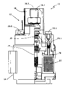
Fig. 1, a perspective view, partly in section, of a relay according to the
invention;
and
Fig. 2, a perspective view of the coil unit and control unit of Fig. 1.
Fig. 1 shows a relay 10 according to the invention, which includes a
connection unit
12 and a coil housing 14. The relay 10 is a bistable relay. The connection
unit 12 has
two main contact terminals 16.1, 16.2. In Fig. 1, a first main contact
terminal 16.1 is
shown. A second main contact terminal 16.2 is concealed by a breakdown
protector 18
in the view in Fig. 1. The connection unit 12 also has three control
electrodes, of which
two control electrodes 20.1, 20.2 are shown in Fig. 1. A third control
electrode is
concealed in the rear portion of the relay 10. The coil housing 14 includes a
coil
arrangement 22, an armature 24, and a control unit 26. The control unit 26 is
embodied on an essentially round circuit board, which has the same diameter as
the
coil arrangement 22. In this way, the control unit 26 can be integrated
compactly with
the coil housing 14 and is simultaneously shielded by it against interference
fields from
-3-

CA 02737696 2011-04-18
outside.
For controlling the relay 10, a control signal in the form of a direct voltage
is applied
to the control electrodes 20.1, 20.2. The control signal is detected by the
control unit
26, which is connected electrically by cushioned contact pins 28.1, 28.2, 28.3
to the
various control electrodes 20.1, 20.2. The control unit 26 evaluates the
control signal
and supplies current to the coil arrangement 22. The magnetic flux induced in
the coil
arrangement 22 moves the armature 24. A main contact bridge 30 is located on
the
armature 24. By means of the main contact bridge 30, an electrical connection
between the main contact terminals 16.1 and 16.2 is opened or closed in
accordance
with the motion of the armature 24.
Fig. 2 shows the coil arrangement 22, the control unit 26 embodied on a
circuit
board, and the cushioned contact pins 28.1, 28.2 and 28.3 of the relay 10
shown in Fig.
1. The relay elements shown in Fig. 2 are all located in the coil housing 14
of the relay
10. The coil arrangement 22 includes a coil 32 and a coil body 34. The control
unit 26
is located directly on the coil body 34. The cushioned contact pins 28.1,
28.2, 28.3 are
electrically connected to the control electrodes. An electrical connection of
the
cushioned contact pins 28.1, 28.2, 28.3 is also embodied extending through the
control
unit 26 to the coil 32.
The wiring of the control unit 26 can preferably be done in three ways:
In a first variant, two cushioned contact pins 28.2, 28.3 are subjected to a
supply
voltage. The relay 10 is switched on by means of a high level at the cushioned
contact
pin 28.1 and switched off again by means of a low level at the cushioned
contact pin
28.1. The range of the high and low levels can be defined freely within the
operating
voltage of the relay.
In a second variant, the cushioned contact pin 28.1 is subjected electrically
to a
negative voltage. The relay is switched on by the application of a positive
voltage at the
cushioned contact pin 28.2, and it is switched off again by the application of
a positive
voltage at the cushioned contact pin 28.3.
-4-

CA 02737696 2011-04-18
Finally, in a third variant, the cushioned contact pin 28.3 is subjected
continuously to
a positive voltage. The relay is then switched on by application of a negative
voltage at
the cushioned contact pin 28.1 and is switched off by application of a
negative voltage
at the cushioned contact pin 28.2.
Once the relay has been switched on or off, the control unit 26 reduces the
coil
current, so that the control unit 26 makes it possible to keep the relay 10 in
the
applicable switching position in virtually powerless fashion.
The control unit 26 is short-circuit-proof and has a protected coil trigger, a
mispolarization protector, and a coil blowout. Moreover, an undervoltage
protector,
which protects the relay against indefinite operating states, is integrated
with the control
unit 26.
The control unit 26 can also be triggered by low-power triggering devices,
such as
on-board computers in vehicles. Locating the control unit 26 in the coil
housing 14
makes a compact structure of the relay 10 possible, so that the relay 10 of
the invention
can replace a conventional relay of the same type. Moreover, the relay with
the
integrated control unit can be embodied as steam-jet-proof.
-5-

Dessin représentatif
Une figure unique qui représente un dessin illustrant l'invention.
États administratifs

2024-08-01 : Dans le cadre de la transition vers les Brevets de nouvelle génération (BNG), la base de données sur les brevets canadiens (BDBC) contient désormais un Historique d'événement plus détaillé, qui reproduit le Journal des événements de notre nouvelle solution interne.

Veuillez noter que les événements débutant par « Inactive : » se réfèrent à des événements qui ne sont plus utilisés dans notre nouvelle solution interne.

Pour une meilleure compréhension de l'état de la demande ou brevet qui figure sur cette page, la rubrique Mise en garde , et les descriptions de Brevet , Historique d'événement , Taxes périodiques et Historique des paiements devraient être consultées.

Historique d'événement

Description Date
Le délai pour l'annulation est expiré 2017-04-18
Demande non rétablie avant l'échéance 2017-04-18
Inactive : Abandon.-RE+surtaxe impayées-Corr envoyée 2016-04-18
Réputée abandonnée - omission de répondre à un avis sur les taxes pour le maintien en état 2016-04-18
Inactive : Demande sous art.37 Règles - Non-PCT 2012-04-18
Demande publiée (accessible au public) 2011-10-29
Inactive : Page couverture publiée 2011-10-28
Inactive : Réponse à l'art.37 Règles - Non-PCT 2011-06-01
Inactive : CIB attribuée 2011-05-16
Inactive : CIB en 1re position 2011-05-16
Inactive : CIB attribuée 2011-05-16
Demande reçue - nationale ordinaire 2011-05-05
Exigences de dépôt - jugé conforme 2011-05-05
Inactive : Demande sous art.37 Règles - Non-PCT 2011-05-05
Inactive : Certificat de dépôt - Sans RE (Anglais) 2011-05-05

Historique d'abandonnement

Date d'abandonnement Raison Date de rétablissement
2016-04-18

Taxes périodiques

Le dernier paiement a été reçu le 2015-03-26

Avis : Si le paiement en totalité n'a pas été reçu au plus tard à la date indiquée, une taxe supplémentaire peut être imposée, soit une des taxes suivantes :

  • taxe de rétablissement ;
  • taxe pour paiement en souffrance ; ou
  • taxe additionnelle pour le renversement d'une péremption réputée.

Veuillez vous référer à la page web des taxes sur les brevets de l'OPIC pour voir tous les montants actuels des taxes.

Historique des taxes

Type de taxes Anniversaire Échéance Date payée
Taxe pour le dépôt - générale 2011-04-18
TM (demande, 2e anniv.) - générale 02 2013-04-18 2013-03-25
TM (demande, 3e anniv.) - générale 03 2014-04-22 2014-03-19
TM (demande, 4e anniv.) - générale 04 2015-04-20 2015-03-26
Titulaires au dossier

Les titulaires actuels et antérieures au dossier sont affichés en ordre alphabétique.

Titulaires actuels au dossier
KISSLING ELEKTROTECHNIK GMBH
Titulaires antérieures au dossier
GUNTER KAISER
KARL STEIMLE
SIMON KALMBACH
Les propriétaires antérieurs qui ne figurent pas dans la liste des « Propriétaires au dossier » apparaîtront dans d'autres documents au dossier.
Documents

Pour visionner les fichiers sélectionnés, entrer le code reCAPTCHA :


Pour visualiser une image, cliquer sur un lien dans la colonne description du document. Pour télécharger l'image (les images), cliquer l'une ou plusieurs cases à cocher dans la première colonne et ensuite cliquer sur le bouton "Télécharger sélection en format PDF (archive Zip)" ou le bouton "Télécharger sélection (en un fichier PDF fusionné)".

Liste des documents de brevet publiés et non publiés sur la BDBC .

Si vous avez des difficultés à accéder au contenu, veuillez communiquer avec le Centre de services à la clientèle au 1-866-997-1936, ou envoyer un courriel au Centre de service à la clientèle de l'OPIC.


Description du
Document 
Date
(aaaa-mm-jj) 
Nombre de pages   Taille de l'image (Ko) 
Description 2011-04-18 5 216
Abrégé 2011-04-18 1 11
Revendications 2011-04-18 1 39
Dessins 2011-04-18 2 42
Dessin représentatif 2011-10-03 1 11
Page couverture 2011-10-14 1 36
Certificat de dépôt (anglais) 2011-05-05 1 157
Rappel de taxe de maintien due 2012-12-19 1 113
Rappel - requête d'examen 2015-12-21 1 117
Courtoisie - Lettre d'abandon (requête d'examen) 2016-05-30 1 164
Courtoisie - Lettre d'abandon (taxe de maintien en état) 2016-05-30 1 172
Correspondance 2011-05-05 1 21
Correspondance 2011-06-01 1 23