Sélection de la langue

Search

Sommaire du brevet 2741344 

Énoncé de désistement de responsabilité concernant l'information provenant de tiers

Une partie des informations de ce site Web a été fournie par des sources externes. Le gouvernement du Canada n'assume aucune responsabilité concernant la précision, l'actualité ou la fiabilité des informations fournies par les sources externes. Les utilisateurs qui désirent employer cette information devraient consulter directement la source des informations. Le contenu fourni par les sources externes n'est pas assujetti aux exigences sur les langues officielles, la protection des renseignements personnels et l'accessibilité.

Disponibilité de l'Abrégé et des Revendications

L'apparition de différences dans le texte et l'image des Revendications et de l'Abrégé dépend du moment auquel le document est publié. Les textes des Revendications et de l'Abrégé sont affichés :

  • lorsque la demande peut être examinée par le public;
  • lorsque le brevet est émis (délivrance).
(12) Demande de brevet: (11) CA 2741344
(54) Titre français: PROCEDE POUR LA FABRICATION DE PANNEAUX ET PLAQUES PREFABRIQUES EN MORTIER ARME
(54) Titre anglais: A METHOD FOR THE MANUFACTURE OF PREFABRICATED REINFORCED MORTAR PANELS AND SLABS
Statut: Réputée abandonnée et au-delà du délai pour le rétablissement - en attente de la réponse à l’avis de communication rejetée
Données bibliographiques
Abrégés

Abrégé français

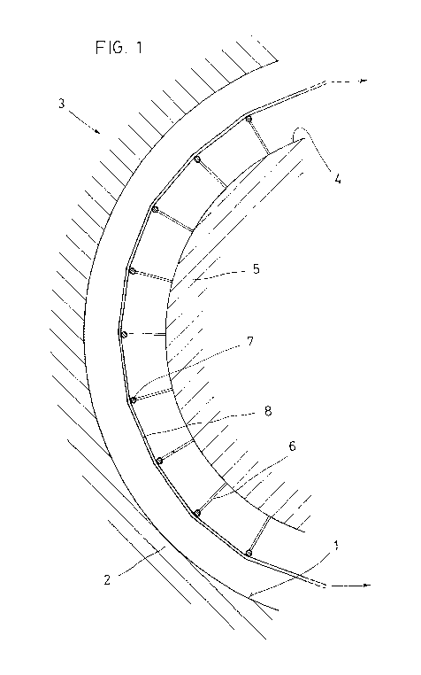
L'invention concerne un procédé pour la fabrication de panneaux et plaques préfabriqués en mortier armé, concrètement un procédé dans lequel on utilise des moules métalliques qui présentent des moyens résistants pour supporter la tension d'armatures biaxiales. Selon le procédé, on utilise un moule (3) qui est formé de deux parois centrales (2, 5) parallèles, qui forment les faces principales du panneau, de deux parois latérales (9), qui relient les côtés des parois centrales (2, 5) et forment les chants latéraux du panneau, et de deux parois d'extrémité, qui relient les bords d'extrémité des parois centrales (2, 5) et latérales (9) et forment les chants d'extrémité du panneau. Entre les parois latérales (9) et les parois d'extrémité, on dispose biaxialement une armature (7, 8) tendue. Enfin, on introduit le mortier à travers un espace adapté prévu dans une des parois centrales (2, 5) latérales (9) et/ou d'extrémité.


Abrégé anglais


A method for the manufacture of prefabricated reinforced mortar panels and
slabs,
particularly one in which metal molds are used that have resistant means to
withstand the stressing of biaxial reinforcement members. According to the
method,
a mold (3) is provided that is formed by two parallel central walls (2, 5),
forming the
major faces of the panel, two sidewalls (9), which connect the sides of the
central
walls (2, 5) and form the lateral edges of the panel, and two end walls which
connect the end edges of the central (2, 5) and sidewalls (9), and form the
end
edges of the panel. A stressed reinforcement member (7, 8) is provided
biaxially
between the sidewalls (9) and the end walls. Finally mortar is introduced
through an
operable space provided in one of the central walls (2, 5), side walls (9)
and/or end
walls.

Revendications

Note : Les revendications sont présentées dans la langue officielle dans laquelle elles ont été soumises.


-7-
CLAIMS
1. - A method for the manufacture of prefabricated reinforced mortar panels
and
slabs, particularly one in which metal molds are used that have resistant
means to
withstand the stressing of biaxial reinforcement members, characterized in
that
there is provided a mold (3) that, being capable of adopting a vertical or
horizontal
position, is formed by two parallel central walls (2, 5), forming the major
faces of the
panel, two sidewalls (9), which connect the sides of the central walls (2, 5)
and form
the lateral edges of said panel, and two upper or front and lower or rear end
walls
depending on the positioning of the mold, which connect the end edges of said
central walls (2, 5) and sidewalls (9), either upper or front and lower or
rear, and
form the end edges of the panel, there being provided biaxially a
reinforcement
member (7, 8) stressed between said sidewalls (9) and said end walls, after
which
mortar is introduced through an operable space provided in one of the central
walls
(2 5), side walls (9) and/or end walls.
2.- The method for the manufacture of prefabricated reinforced mortar panels
and
slabs according to claim 1, characterized in that said parallel central walls
(2, 5),
said sidewalls (9) and said end walls are of flat rectangular configuration.
3. - The method for the manufacture of prefabricated reinforced mortar panels
and
slabs according to claim 1, characterized in that said parallel central walls
(2, 5) are
of curved configuration in only one of their dimensions, said sidewalls (9)
are
rectangular and flat and said end walls are flat with an arcuate
configuration.
4. - The method for the manufacture of prefabricated reinforced mortar panels
and
slabs according to claim 1, characterized in that said parallel central walls
(2, 5),
said sidewalls (9) and said end walls have a Teflon coating on their molding
surface.
5. - The method for the manufacture of prefabricated reinforced mortar panels
and
slabs according to claim 2, characterized in that said reinforcement members
(7, 8)
stressed between said sidewalls (9) and said end walls are in planes parallel
to said

-8-
central walls (2, 5) and constitute two orthogonal groups, in each one of
which said
reinforcement members (7, 8) follow rectilinear trajectories parallel to each
other.
6. - The method for the manufacture of prefabricated reinforced mortar panels
and
slabs according to claim 3, characterized in that said reinforcement members
(7, 8)
stressed between said sidewalls (9) follow uneven parallel trajectories
forming
vertices located on an imaginary arc and supported on support members (6)
inserted perpendicularly in the convex face (4) of the central wall (5) of
smaller
dimension of curvature.
7. - The method for the manufacture of prefabricated reinforced mortar panels
and
slabs according to claim 3, characterized in that said central wall (5) of
smaller
dimension of curvature is provided on the concave face thereof,
perpendicularly to
said concave face, with transverse reinforcement means (10) to withstand the
stresses exerted by said reinforcement members (8) of uneven trajectory due to
the
stressing thereof.
8. - The method for the manufacture of prefabricated reinforced mortar panels
and
slabs according to claim 1, characterized in that said sidewalls (9) and said
end
walls are connected to said central walls (2, 5) through operable closing
means
(12).
9. - The method for the manufacture of prefabricated reinforced mortar panels
and
slabs according to claim 7, characterized in that said transverse
reinforcement
means (10) disposed parallel to each other in said central wall (5) of smaller
curvature are connected by spacer bars (11) perpendicular to said transverse
reinforcement means (10).
10. - The method for the manufacture of prefabricated reinforced mortar panels
and
slabs according to claim 5, characterized in that the support members (6)
comprise
a head (15) provided with two orthogonal grooves (16) for guiding and seating
the
points of intersection of the stressed reinforcement members (7, 8).

-9-
11. - The method for the manufacture of prefabricated reinforced mortar panels
and
slabs according to claim 6, characterized in that the support members (6)
comprise
two diametrical through holes (18), located orthogonally in two adjacent
parallel
planes in the vicinity of the head thereof.
12. - The method for the manufacture of prefabricated reinforced mortar panels
and
slabs according to claim 1, characterized in that the mold may include, in at
least its
central walls (2, 5), a jacket for the circulation of a heat conditioned
fluid.

Description

Note : Les descriptions sont présentées dans la langue officielle dans laquelle elles ont été soumises.


CA 02741344 2011-04-20
-1-
A METHOD FOR THE MANUFACTURE OF PREFABRICATED REINFORCED
MORTAR PANELS AND SLABS
DESCRIPTION
Object of the invention
The present invention relates to a method for the manufacture of prefabricated
reinforced mortar panels and slabs, particularly one in which metal molds are
used
that have resistant means to withstand the stressing of biaxial reinforcement
members and is organized so that both flat and curved panels and slabs,
biaxially
prestressed, can be obtained, as prefabricated items.
Background of the invention
Some patents are known in which shuttering for the construction of walls of
curved
surface are contemplated, such as the patents ES 2 084 868, ES 2 141 010 and
ES
2 178 604, in all of which it is seen that they refer to shuttering
arrangements that
allow the construction of concrete walls "in situ" having a curved surface
and, in all
cases, with the sole possibility of being reinforced with non-prestressed
reinforcement members and only in the sense of the generatrix of the curve.
In these cases it is impossible to obtain prefabricated panels and slabs
having a
curved surface and with biaxially prestressed reinforcement members.
On the other hand, the traditional methods of molding reinforced mortar panels
and
slabs, up to now practically only of flat configuration, use open top
horizontal molds,
which make it difficult to obtain a correct setting because of the evaporation
of the
water from the mortar, and which require their molding surface to be covered
by of
a mold stripping agent.

CA 02741344 2011-04-20
-2-
Description of the invention
With the purpose of being able to manufacture panels and slabs as
prefabricated
items of any configuration, having either a flat, curve, warped or spherical
surface
and with prestressed biaxial reinforcement members, at the same time as to
avoid
an undesired evaporation of the water from the mortar in the setting process,
the
solution has been adopted of molding the said panels and slabs in closed molds
and with guide means for the reinforcement members in curved trajectories.
According to the preceding solution the method for the manufacture of
prefabricated
reinforced mortar panels and slabs has been developed which is the object of
the
invention, which consists of the fact that there is provided a mold that,
being
capable of being placed in the vertical or horizontal position, is formed by
two
parallel central walls, forming the major faces of the panel, two sidewalls,
which
connect the sides of the central walls and form the lateral edges of this
panel, and
two upper or front and lower or rear end walls depending on the positioning of
the
mold, which connect the end edges of the central and sidewalls, either upper
or
front and lower or rear and form the end edges of the panel, there being
provided
biaxially a stressed reinforcement member between the sidewalls and the end
walls,
after which mortar is introduced through an operable space provided in one of
the
central, side and/or end walls.
One feature of the invention consists of, in one embodiment, the parallel
central
walls, the sidewalls and the end walls having a flat rectangular
configuration,
whereas in another embodiment the central walls have a curved configuration
in, at
least, one of their dimensions, the sidewalls are rectangular and
substantially flat,
whereas the end walls are flat and have an arcuate, preferably annular,
configuration.
A further feature of the invention is that the parallel central walls, the
sidewalls and
the end walls have a Teflon coating on their molding face.

CA 02741344 2011-04-20
-3-
Yet another feature of the invention is that, in the case of flat panels and
slabs, the
stressed reinforcement members between the sidewalls and the end walls are in
planes parallel to the central walls and form two orthogonal groups, in each
one of
which the reinforcement members follow rectilinear trajectories parallel to
each
other, whereas, in the case of curved panels and slabs, the stressed
reinforcement
members between the sidewalls follow uneven parallel trajectories forming
vertices
located on an imaginary arc and supported on support members inserted
perpendicularly in the convex face of the central wall having the smaller
dimension
of curvature.
Another feature of the invention is that the central wall having the smaller
dimension
of curvature has on its concave face, perpendicularly thereto, transverse
reinforcement means to withstand the stresses exerted by the uneven trajectory
reinforcement members due to the stressing thereof, at the same time as the
transverse reinforcement means, which are disposed parallel to each other, in
the
central wall having smaller curvature, are connected by means of spacer bars
perpendicular thereto.
Finally, other features that constitute details of the invention will be
disclosed
throughout the description thereof that will be developed below.
Brief description of the drawings
In order to facilitate the understanding of the foregoing ideas, there is
described
hereinafter the method for the manufacture of prefabricated reinforced mortar
panels and slabs using preferred means for obtaining them, with reference to
the
illustrative drawings attached hereto. In the drawings:
Figure 1 schematically shows the functional principle of a mold for the
manufacture
of an arcuate panel with the installation of the prestressed biaxial
reinforcement
members.
Figure 2 is a top view of a central portion of an embodiment of a mold made
according to the scheme of the previous Figure.

CA 02741344 2011-04-20
-4-
Figure 3 is a perspective view of the mold of the previous Figure seen from
its face
having the smaller radius of curvature, in which the transverse reinforcement
means
are to be seen.
Figure 4, is a perspective view of an embodiment of a support member for a
point of
intersection of the reinforcement members.
Figure 5, is a perspective view of another embodiment of a support member for
a
point of intersection of the reinforcement members that is functionally
equivalent to
that of the previous Figure.
Figure 6, is a perspective view of a variant of the embodiment of the support
member of the previous Figure.
Figure 7 is a top view, partly in cross section, of a possible embodiment of
the
operable closing means that join the central walls to the sidewalls during the
molding operation.
Description of an embodiment of the invention
In Figure 1 there is shown the functional principle of the invention applied
to the
case in which the method of the invention is for obtaining a curved panel or
slab.
Thus, there is shown the concave face 1 of a major central wall 2 of a mold 3
for
curved panels that is parallel to the convex face 4 of a minor central wall 5,
in which
there are installed support members 6 for the longitudinal 7 and transverse 8
prestressed reinforcement members.
The space between these central major 2 and minor 5 walls, in which the
longitudinal 7 and transverse 8 reinforcement members with their support
members
6 are incorporated, is for receiving the mass of mortar to be molded. The said
longitudinal 7 and transverse 8 reinforcement members 7 will be embedded in
said
mass with their support members 6 that will be unattached to the minor central
wall
5.
In order to reduce the method of the invention to practice, it is necessary to
have a
mold 3, capable of being placed in the vertical or horizontal position, which
is

CA 02741344 2011-04-20
-5-
formed by two central major 2 and minor 5 walls which, being parallel, will
form the
major faces of the panel and two sidewalls 9, that connect the sides of
central major
2 and minor 5 walls and form the side edges of the panel. The mold 3 is also
formed by two end walls, not shown in the drawings as being expected, that are
upper or front, and lower or rear, according to the positioning of the mold.
These,
two end walls connect the end edges of central walls 2 and 5 and sidewalls 9,
as
being upper or front and lower or rear, and form the end edges of the panel.
Finally,
the longitudinal 7 and transverse 8 reinforcement members are arranged
biaxially,
stressed between the sidewalls 9 and the end walls, after which mortar is
poured
through a operable space provided in one of the central walls 2, 5, sidewalls
9
and/or end walls, which have not been shown either as in the previous case.
The invention contemplates the cases in which the parallel central walls 2, 5,
the
sidewalls 9 and end walls are of flat rectangular configuration, as well as
the cases
currently treated in which the said parallel central major 2 and minor 5 walls
have a
curved configuration in only one of their dimensions, the sidewalls 9 are
rectangular
and flat and the end walls are flat with an arcuate configuration.
In Figures 1, 2 and 3 it is to be seen that longitudinal 7 and transverse 8
reinforcement members stressed between the sidewalls 9 and end walls are in
surfaces parallel to the central major 2 and minor 5 walls and form two
orthogonal
groups, in each of which the reinforcement members 7, 8 follow rectilinear
trajectories parallel to each other, in the case where said central walls are
flat,
whereas the longitudinal7 and transverse 8 reinforcement members stressed
between the sidewalls 9 follow uneven parallel trajectories forming vertices
located
in an imaginary arc and supported on support members 6 inserted
perpendicularly
in the convex face 4 of the minor central wall 5.
In Figures 2 and 3, it is to be seen that the minor central wall 5 has in its
concavity
and perpendicularly thereto transverse reinforcement means 10 to withstand the
stresses exerted by the reinforcement members of uneven trajectory due to the
stressing thereof. These transverse reinforcement means 10 are disposed
parallel

CA 02741344 2011-04-20
-6-
to each other in the minor central wall 5 and are connected by means of spacer
bars 11 perpendicular thereto.
On the other hand, as shown in Figure 7, the sidewalls 9, and also the end
walls, in
a case not shown, are connected to the central major 2 and minor 5 walls by
operable closing means 12.
Figure 4 shows a variant of the support member 6 that is formed by a forked
rod 13.
Other embodiments of the support members 6 comprise, in Figure 5, a body 14
with
a head 15 provided with two orthogonal grooves 16 for guiding and seating the
points of intersection of the stressed longitudinal 7 and transverse 8
reinforcement
members and, in Figure 6, they comprise a body 17 provided with two
diametrical
through holes 18, located orthogonally in two adjacent parallel planes, in the
vicinity
of a head 19 through which the longitudinal 7 and transverse 8 reinforcement
members pass.
In all the cases it is contemplated that mold 3, both in its curved version
and in the
not shown flat version, may comprise, in at least its central major 2 and
minor 5
walls, a jacket for the circulation of a heat conditioned fluid.

Dessin représentatif
Une figure unique qui représente un dessin illustrant l'invention.
États administratifs

2024-08-01 : Dans le cadre de la transition vers les Brevets de nouvelle génération (BNG), la base de données sur les brevets canadiens (BDBC) contient désormais un Historique d'événement plus détaillé, qui reproduit le Journal des événements de notre nouvelle solution interne.

Veuillez noter que les événements débutant par « Inactive : » se réfèrent à des événements qui ne sont plus utilisés dans notre nouvelle solution interne.

Pour une meilleure compréhension de l'état de la demande ou brevet qui figure sur cette page, la rubrique Mise en garde , et les descriptions de Brevet , Historique d'événement , Taxes périodiques et Historique des paiements devraient être consultées.

Historique d'événement

Description Date
Le délai pour l'annulation est expiré 2015-10-28
Demande non rétablie avant l'échéance 2015-10-28
Inactive : Abandon. - Aucune rép dem par.30(2) Règles 2015-03-16
Réputée abandonnée - omission de répondre à un avis sur les taxes pour le maintien en état 2014-10-28
Inactive : Dem. de l'examinateur par.30(2) Règles 2014-09-16
Inactive : Rapport - Aucun CQ 2014-09-10
Lettre envoyée 2013-10-03
Requête d'examen reçue 2013-09-25
Toutes les exigences pour l'examen - jugée conforme 2013-09-25
Exigences pour une requête d'examen - jugée conforme 2013-09-25
Inactive : Page couverture publiée 2011-06-22
Inactive : Notice - Entrée phase nat. - Pas de RE 2011-06-10
Inactive : Inventeur supprimé 2011-06-10
Inactive : CIB attribuée 2011-06-09
Inactive : CIB en 1re position 2011-06-09
Inactive : CIB attribuée 2011-06-09
Demande reçue - PCT 2011-06-09
Inactive : CIB attribuée 2011-06-09
Exigences pour l'entrée dans la phase nationale - jugée conforme 2011-04-20
Demande publiée (accessible au public) 2010-05-06

Historique d'abandonnement

Date d'abandonnement Raison Date de rétablissement
2014-10-28

Taxes périodiques

Le dernier paiement a été reçu le 2013-10-07

Avis : Si le paiement en totalité n'a pas été reçu au plus tard à la date indiquée, une taxe supplémentaire peut être imposée, soit une des taxes suivantes :

  • taxe de rétablissement ;
  • taxe pour paiement en souffrance ; ou
  • taxe additionnelle pour le renversement d'une péremption réputée.

Les taxes sur les brevets sont ajustées au 1er janvier de chaque année. Les montants ci-dessus sont les montants actuels s'ils sont reçus au plus tard le 31 décembre de l'année en cours.
Veuillez vous référer à la page web des taxes sur les brevets de l'OPIC pour voir tous les montants actuels des taxes.

Historique des taxes

Type de taxes Anniversaire Échéance Date payée
TM (demande, 2e anniv.) - générale 02 2010-10-28 2011-04-20
Taxe nationale de base - générale 2011-04-20
TM (demande, 3e anniv.) - générale 03 2011-10-28 2011-09-02
TM (demande, 4e anniv.) - générale 04 2012-10-29 2012-10-10
Requête d'examen - générale 2013-09-25
TM (demande, 5e anniv.) - générale 05 2013-10-28 2013-10-07
Titulaires au dossier

Les titulaires actuels et antérieures au dossier sont affichés en ordre alphabétique.

Titulaires actuels au dossier
CARLOS FRADERA PELLICER
Titulaires antérieures au dossier
S.O.
Les propriétaires antérieurs qui ne figurent pas dans la liste des « Propriétaires au dossier » apparaîtront dans d'autres documents au dossier.
Documents

Pour visionner les fichiers sélectionnés, entrer le code reCAPTCHA :


Pour visualiser une image, cliquer sur un lien dans la colonne description du document. Pour télécharger l'image (les images), cliquer l'une ou plusieurs cases à cocher dans la première colonne et ensuite cliquer sur le bouton "Télécharger sélection en format PDF (archive Zip)" ou le bouton "Télécharger sélection (en un fichier PDF fusionné)".

Liste des documents de brevet publiés et non publiés sur la BDBC .

Si vous avez des difficultés à accéder au contenu, veuillez communiquer avec le Centre de services à la clientèle au 1-866-997-1936, ou envoyer un courriel au Centre de service à la clientèle de l'OPIC.


Description du
Document 
Date
(aaaa-mm-jj) 
Nombre de pages   Taille de l'image (Ko) 
Description 2011-04-19 6 231
Dessins 2011-04-19 4 155
Abrégé 2011-04-19 1 21
Dessin représentatif 2011-04-19 1 20
Revendications 2011-04-19 3 100
Avis d'entree dans la phase nationale 2011-06-09 1 196
Rappel - requête d'examen 2013-07-01 1 118
Accusé de réception de la requête d'examen 2013-10-02 1 176
Courtoisie - Lettre d'abandon (taxe de maintien en état) 2014-12-22 1 171
Courtoisie - Lettre d'abandon (R30(2)) 2015-05-10 1 164
PCT 2011-04-19 6 190