Note : Les descriptions sont présentées dans la langue officielle dans laquelle elles ont été soumises.
CA 02741370 2014-11-05
CONNECTION DEVICE
Technical Field
This disclosure relates to connection devices for expanded cellular
confinement
structures for the confinement of infill material. In particular, this
disclosure relates to
connectors and methods used for fastening together at least two expanded
cellular
confinement structures.
Background
A cellular confinement structure serves to increase the load bearing capacity,
stability,
and erosion resistance of infill materials which are placed within the cells
of the system. A
commercially available system is Geoweb plastic web confinement structure
sold by Presto
Products, Inc., Appleton, Wisconsin. Geoweb cells are made from high density
polyethylene
strips that are joined by welds on their faces in a side-by-side relationship
at alternating spaces
so that when the strips are stretched out in a direction perpendicular to the
faces of the strips,
the resulting web section is honeycomb-like in appearance, with sinusoidal or
undulated-
shaped cells. Geoweb sections are lightweight and are shipped in their
collapsed form for
ease in handling and installation. Geoweb systems have been described in U.S.
Pat.
6,395,372; 4,778,309; 4,965,097; and 5,449,543.
The cellular confinement structures are typically arranged adjacent to each
other and
then connected together. In the past, these sections have been connected
together by using
staples, wires, cable ties, etc. These devices are labor-intensive and consume
excessive
construction time. In many implementations, these types of connections are
difficult to use
because of the particular situation or terrain. Most often, these types of
connection systems
require power from generators and air actuation from compressors. The
requirement for
power can add to the difficulty, given the particular environment or terrain
that such cellular
confinement systems are typically placed. The unit cost per connection can be
quite high on
smaller projects as the fixed costs for supply of generators and air
compressors are similar to a
small installation as would be required for a large installation. Moreover,
some of these
connection devices provide relatively weak structural connections and are non-
durable. In
1
CA 02741370 2014-11-05
some implementations, these are not problems. In many applications, however,
speed is
important and the availability of power equipment is challenging. In many
implementations,
long-term durability is mandatory. Improvements are desirable.
Summary of the Disclosure
According to the present invention, there is provided a connection device for
fastening
two expanded cellular confinement structures; the connection device
comprising:
(a) an insertion member having first and second opposite insertion ends and
an
insertion member extension therebetween;
(i) the insertion member having a first length between the
first and second
insertion ends;
(b) an integral shank extending generally perpendicular from the insertion
member
extension and being spaced from each of the first and second insertion ends;
and
(c) an integral handle member extending generally perpendicular from the
shank at
an end of the shank remote from the insertion member; the handle member having
first and
second handle ends and a handle member extension therebetween;
(i) the shank being spaced from each of the first and second handle ends;
(ii) the handle member having a second length between the first and second
handle ends;
(iii) the shank having a third length between the insertion member and the
handle member;
wherein:
the second length is greater than the first length; and
the third length is less than half of the first and second lengths.
Preferably, a connection device for fastening two expanded cellular
confinement
structures is provided. In general, the connection device includes an
insertion member having
first and second opposite insertion ends and an insertion member extension
therebetween. An
integral shank extends from the insertion member extension and is spaced from
each of the
first and second insertion ends. A handle member extends generally from the
shank at an end
of the shank that is remote from the insertion member. The handle member has
first and
2
CA 02741370 2014-11-05
second handle ends and a handle member extension therebetween. The shank is
spaced from
each of the first and second handle ends.
According to the present invention, there is also provided a cellular
confinement
system comprising the connection device as described above, the system
comprising:
(a) a first unitary web of cells made from elongated plastic strips bonded
together
in spaced apart areas; the strips forming walls of the cells; at least some of
the cells defining
open slots;
(b) a second unitary web of cells made from elongated plastic strips bonded
together in spaced apart areas; the strips forming walls of the cells; at
least some of the cells
defining open slots;
(0 at least one open slot of the first unitary web of cells
being aligned with
at least one open slot of the second unitary web of cells to result in a cell
overlap region; the
cell overlap region having opposite first and second sides; and
(c) at least one of the connection device, fastening the first unitary web
of cells and
the second unitary web of cells together;
(i) the insertion member being located on the first side of the cell
overlap
region;
(ii) the shank extending through the cell overlap region by extending
through both of the aligned one open slot of the first unitary web of cells
and the one open
slot of the second unitary web of cells;
(iii) the handle member being located the second side of the cell overlap
region.
Preferably, in another aspect, a cellular confinement system is provided. The
cellular
confinement system includes first and second unitary webs of cells made from
elongated
plastic strips bonded together in spaced apart areas. The strips form walls of
the cells and at
least some of the cells define open slots. At least one open slot of a first
unitary web of cells is
aligned with at least one open slot of a second unitary web of cells to result
in a cell overlap
region. The cell overlap region has opposite first and second sides. At least
one connection
3
CA 02741370 2014-11-05
device fastens the first unitary web of cells and the second unitary web of
cells together. The
connection device can be the type as characterized above. When used, the
insertion member
is located on the first side of the cell overlap region. The shank extends
through the cell
overlap region by extending through both of the aligned slots of the first and
second unitary
web of cells. The handle member is located on the second side of the cell
overlap region.
According to the present invention, there is also provided a method of
fastening two
expanded cellular confinement structures together using the connection device
as described
above, the method comprising:
(a)
aligning two expanded cell confinement structures so that at least one open
slot
defined by a first unitary web of cells is aligned with at least one open slot
defined by a second
unitary web of cells to form an overlap region having opposite first and
second sides;
(b)
inserting the insertion member of the connection device, from the second
side
of the overlap region through the aligned open slots of the overlap region to
provide:
(i) the insertion member on the first side of the overlap region;
(ii) the handle member of the connection device on the second side of the
overlap region; and
(iii) the shank between the insert member and the handle member
extending through the overlap region; and
(c)
rotating the handle member to rotate the connection device within the
overlap
region.
Preferably, in another aspect, a method of fastening two expanded cellular
confinement structures together is provided. The method includes aligning two
expanded
cellular confinement structures so that at least one open slot defined by a
first unitary web of
cells is aligned with at least one open slot defined by a second unitary web
of cells to form an
overlap region having first and second sides. The method includes inserting an
insertion
member of a connection device from the second side of the overlap region
through the aligned
open slots of the overlap region to provide: the insertion member on the first
side of the
overlap region; a handle member of the connection device on the second side of
the overlap
3a
CA 02741370 2014-11-05
region; and a shank member between the insert member and the handle member
extending
through the overlap region.
In some implementations, the method further includes rotating the handle to
rotate
the connection device within the overlap region.
Brief Description of the Drawings
FIG. 1 is a schematic, exploded perspective view of a cellular confinement
system and
connection devices, prior to assembly end-to-end, utilizing principles in
accordance with this
disclosure;
FIG. 1A is a schematic, exploded perspective view of a cellular confinement
system and
connection devices, prior to lateral assembly, utilizing principles in
accordance with this
disclosure;
FIG. 2 is a perspective view of two cells that are part of an expanded
cellular
confinement structure prior to being connected together;
FIG. 3 is a perspective view of two expanded cellular confinement structures
connected
together utilizing connection devices constructed in accordance with
principles of this
disclosure;
FIG. 4 is a perspective view of one embodiment of a connection device,
constructed in
accordance to principles of this disclosure;
FIG. 5 is another perspective view of the connection device of FIG. 4;
3b
CA 02741370 2011-04-20
WO 2010/053783 PCT/US2009/062359
FIG. 6 is a top plan view of the connection device of FIGS. 4 and 5;
FIG. 7 is an end view of the connection device of FIG. 6;
FIG. 8 is another end view of the connection device of FIG. 6,
depicting the opposite end of that shown in FIG. 7;
FIG. 9 is a top plan view of a second embodiment of connection
device constructed in accordance with principles of this disclosure;
FIG. 10 is a perspective view of the connection device of FIG. 9;
FIG. 11 is a top plan view of the connection device of FIG. 9;
FIG. 12 is a perspective, top view of the connection device of FIGS.
9-11;
FIG. 13 is a schematic, perspective view of a step of using the
connection device along with a tendon;
FIG. 14 is a schematic, perspective view of another step of using the
connection device with a tendon; and
FIG. 15 is a schematic, perspective view of another step of using the
connection device with a tendon.
Detailed Description
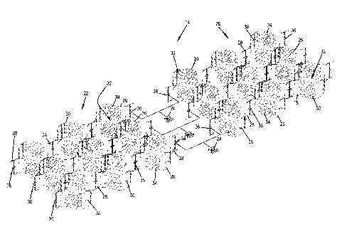
In FIGS. 1 and 1A, there is depicted a cellular confinement system
14. In the particular implementation shown, the cellular confinement system 14
includes first and second unitary webs of cells 18. The first web of cells is
shown at
20, while the second web of cells is shown at 22. In the embodiment shown, the
cellular confinement system 14 further includes at least one connection device
24 for
fastening together the first web 20 and second web 22.
FIG. 1 shows the system 14 before the first and second webs 20, 22
are connected together in an end-to-end manner. FIG. 1A shows the system 14
before the first and second webs 20, 22 are connected together side-by-side
(laterally). Each of the expanded cellular confinement structures 18 has a
plurality
of strips of plastic 26 that are bonded together, one strip to the next at
alternating and
equally spaced bonding areas 28 to form cell walls 30 of individual cells 32.
When
the plurality of strips 26 are stretched in a direction perpendicular to the
face of the
strips, the strips 26 bend in a sinusoidal manner and form webs 20, 22 of
cells 32 in
4
CA 02741370 2016-02-17
,
, .
a repeating cell pattern. Each cell 32 has a cell wall 30 that is made up from
one strip
26 and a cell wall 30 made from a different strip 26.
In this embodiment, the strips 26 define apertures 34. The apertures 34
can be used to accommodate tendons to reinforce the webs 20, 22 and improve
the
stability of web installations by acting as continuous, integral anchoring
members to
prevent unwanted displacement of the webs 20, 22. The apertures 34 also help
to allow
for aggregate interlock while maintaining sufficient wall stiffness for
construction site
infilling. Optimized aperture sizes and patterns are described in U.S. Pat.
6,395,372.
FIG. 2 shows two cells 32. The cells 32 in FIG. 2 differ somewhat from the
depiction in FIG. 1, in that the strips 26 do not contain all of the apertures
34 as
depicted in FIG. 1. The apertures 34 can be used optionally, depending upon
the
implementation. The option depicted in FIG. 2 does not show apertures 34 in
the strips
26. FIG. 2 does depict, however, open slots 36 defined by the cell walls 30 in
the strips
26. The slots 36 are utilized to cooperate with connection device 24 in order
to fasten
together adjacent webs 20, 22.
FIG. 3 shows the cellular confinement system 14 with the first web 20 and
the second web 22 fastened together by connection device 24. In the embodiment
of
FIG. 3, at least one connection device 24 is used, and as shown, a plurality
of
connection devices 24 is used. FIG. 3 shows specifically two connection
devices 24.
Still in reference to FIG. 3, a cell overlap region 38 is depicted. In
particular, there are two cell overlap regions 38 depicted. The cell overlap
region, as
shown, includes an open slot 36 of the first unitary web of cells 20 aligned
with open
slot 36 of the second unitary web of cells 22. The cell overlap region 38
defines a first
side 40 and an opposite second side 42. The connection device 24 can be seen
penetrating or passing through the overlap region 38 with part of the
connection device
24 on the first side of the overlap region 38, while another portion of the
connection
device 24 can be seen in phantom on the second side 42 of the overlap region
38. An
example of this will be described further below.
Attention is directed to FIGS. 4-8. FIGS. 4-8 depict one example
embodiment of connection device 24. In the embodiment depicted, the connection
device 24 includes an insertion member 44. The insertion member 44 has first
and
5
CA 02741370 2011-04-20
WO 2010/053783
PCT/US2009/062359
second opposite insertion ends 46, 47 and an insertion member extension 48
between the first insertion member end 46 and second insertion member end 47.
A
first length is defined by the distance between the first insertion member end
46 and
second insertion member end 47.
In one embodiment, the first insertion member end 46 is tapered, by
having a generally rounded triangular shape 50. This shape is required to
provide a
convenient and expedited use of the connection device 24 allowing for maximum
width of the insertion member and therefore maximum load distribution of the
forces upon the insertion member once placed in use.
In this embodiment, the second insertion end 47 is depicted as having
a tapered end. As can be seen in FIG. 4, in this embodiment, the second
insertion
end 47 has a rounded triangular shape 52. This shape can help provide a fast
and
convenient use of the connection device 24 when connecting together and first
and
second webs 20, 22.
In the example embodiment shown, the insertion member 44 includes
a pair of insertion member plates 54, 55. In the example shown, the insertion
member plates 54, 55 are parallel to each other. In the example shown, the
plates
54, 55 are joined by a bight section 56. In the example shown, the insertion
member
plates 54, 55 are spaced apart from each other and define a volume 58
therebetween.
In one embodiment, the insertion member 44 has a size selected to cooperate
with
the size of the slot 36. Useable lengths for the insertion member 44 is less
than 70
mm, for example, 20-60 mm, and in particular, 35-50 mm. The width of the
insertion member 44 from an exterior of the insertion member plate 54 to the
exterior of the insertion member plate 55 is also selected to cooperate with
the
dimension of the slots 36. In this embodiment, the width will be less than 20
mm,
for example, 4-12 mm.
At an end of the insertion member plates 54, 55 opposite of the bight
section 56 are a pair of bridges 61, 62 that blocks access to the volume 58
from the
region above the insertion member 44. For example, if the connection device 24
is
accommodating a tendon in a portion of the connection device above the
insertion
member 44, the bridges 61, 62 will prevent the tendon from sliding within the
volume 58.
6
CA 02741370 2011-04-20
WO 2010/053783 PCT/US2009/062359
Still in reference to FIGS. 4-8, one example connection device 24
includes an integral shank 64 extending from the insertion member extension
member 48 and being spaced from each of the first and second insertion member
ends 46, 47. A variety of implementations are possible. In the embodiment
depicted, the shank 64 extends generally perpendicular from the insertion
member
extension 48.
In one example, the shank 64 includes a pair of shank plates 66, 67.
In the embodiment shown, the shank plates 66, 67 are parallel to each other
and
spaced apart to define an open volume 68 therebetween.
The shank 64 has a length that is defined as being between the
insertion member 44 and a handle member 70, described below. The length of the
shank 64 is less than the length of the insertion member 44, in one example.
In the embodiment shown, the connection device 24 includes handle
member 70. Preferably, the handle member 70 is integral with the shank 64. The
handle member 70 extends from the shank 64 at an end of the shank 64 remote
from
the insertion member 44.
In the example depicted, the handle member 70 has first and second
handle ends 72, 73. Between the first handle end 72 and the second end 73 is a
handle member extension 74.
In the embodiment shown, the shank 64 is spaced from each of the
first and second handle ends 72, 73.
The handle member 70 has a length defined between the first handle
end 72 and the second handle end 73. While many designs are contemplated, in
the
particular embodiment illustrated, the length of the handle member 70 is
greater than
the length of the insertion member 44. In one example, the length of the shank
64 is
less than half of the length of the handle member 70 and insertion member 44.
These relative dimensions cooperate with the slot 36 and allow for quick,
convenient
fastening of the first and second webs 20, 22.
In example embodiments, the length of the handle member 70 is not
greater than 100 mm, typically, 30-80 mm, for example, 45-55 mm.
In the embodiment shown, the length of the handle member 70 is at
least 10 percent greater than the length of the insertion member 44. This
relative
7
CA 02741370 2011-04-20
WO 2010/053783
PCT/US2009/062359
geometry helps to ensure that the connection device 24 will stay in place
within the
slot 36 and not work its way out.
In the embodiment shown, the handle member extension 74 includes
first and second ears 76, 77 projecting therefrom. The ears 76, 77 are
projecting
away from the insertion member 44. In the embodiment shown, the first and
second
ears 76, 77 are rounded and are even with the first and second handle ends 72,
73.
Still in reference to FIGS. 4-8, the handle member 70 further includes
a base plate 80 and angled handle plate 81 extending from the base plate 80.
The
angled handle plate 81 joins the base plate 80 at an intersection 82. From the
intersection 82, the angled handle plate 81 extends at an angle from the base
plate 82
until reaching the shank plate 66 of the shank 64. The angled handle plate 81
and
the base plate 80 define a volume 84 therebetween. A pair of handle bridges
86, 87
extend between the angled handle plate 81 and base plate 80 at a portion of
the
handle member extension 74 that is opposite of the ears 76, 77. The bridges
86, 87
can help prevent a tendon that is accommodated within the volume 68 of the
shank
plates 66, 67 from passing into the volume 84 of the handle member 70.
Turning again to FIG. 3, it can be seen that in use, the connection
device 24 will have the insertion member 44011 one side 40 of the overlap
region
and the handle member 70 on second side 42 of the overlap region 38. The shank
64 extends through the overlap region 38. Methods of using the connection
device
24 are described further below. The connection device 24 can also be made from
a
single, solid piece of material, such as being cast in solid plastic.
A second embodiment of connection device 24 is depicted in FIGS.
9-12. The connection device 24 depicted in FIGS. 9-12 includes an insertion
member 90, a shank 92, and a handle member 94. In this embodiment of
connection
device 24, there is further included a bearing member 96. The bearing member
96
extends from the shank 92 and is spaced from each of the insertion member 90
and
handle member 94.
In the embodiment shown, the beating member 96 includes a pair of
arms 98, 99 extending from the shank 92. As can be seen in FIGS. 11 and 12,
each
of the arms 98, 99 has a width that is greater than a width of the insertion
member 90
and handle member 94. The bearing member 96 is shaped for surface contact and
8
CA 02741370 2011-04-20
WO 2010/053783
PCT/US2009/062359
load transfer with the strip 26. In use, the bearing member 96 will be on the
same
side 42 of the cell overlap region 38 as handle member 94.
In this embodiment, the handle member 94 has first and second ears
101, 102 that project toward the insertion member 90.
In use, the connection device 24 can be utilized to fasten two
expanded cell confinement structures together. The method includes aligning
two
expanded cell confinement structures 18 so that at least one open slot 36
defined by
first web 20 is aligned with at least one slot 36 defined by second web 22 to
form
overlap region 38.
Connection device 24 is provided. Connection device 24 is used by
inserting the insertion member 44, 90 from the second side 42 of the overlap
region
38 through the aligned open slots 36 of the overlap region 38. This provides
the
insertion member 44, 90 on the first side 40 of the overlap region 38. It
provides the
handle member 70, 94 on the second side 42 of the overlap region 38. It
provides
the shank 64, 92 to extend through the overlap region 38.
The method also includes rotating the handle member 70, 94 to rotate
the connection device 24 within the overlap region 38. This helps to lock the
connection device 24 within the slots 36.
In some implementations, the method can further include a step of
orienting a tendon to pass through volume 68 defined by the shank 64 and
through
the overlap region 38.
An example of use of a tendon 110 is shown in connection with the
connector device 24 of FIGS. 9-12 as shown in FIGS. 13-15. In FIG. 13, the
tendon
110 is illustrated as wrapped around the handle member 94 at wrap 112. The
tendon
110 is positioned under the handle member 94 and wrapped up and over one side
of
the handle 94. The tendon continues wrapping around the upper portion of the
handle 94 to form a cross-wrap. In FIG. 13, it can be seen how the insertion
member 90 is inserted or engaged into the slots 36 of two adjacent webs 20,
22,
either end-to-end or edge-to-edge. The tendon 110 can also be seen extending
through the slots 36 of the webs 20, 22, although the slots 36 are not visible
in FIG.
13. FIG. 14 shows full engagement of the connector device 24 through the slots
36.
In FIG. 14, the final step of rotating the connector device 24 to lock the
connector
9
CA 02741370 2011-04-20
WO 2010/053783
PCT/US2009/062359
device 24 within the slots 36 is illustrated. By comparing FIGS. 14 and 15, it
can be
seen that the connector device 24 is rotated about 90 degrees.
Preferably, the step of rotating includes rotating the handle member
70, 94 about 90 degrees.
In use, the slots 36 will be non-circular, for example, elliptical, or
elongated-circular, or racetrack-shaped. In one embodiment, the slots 36 are
shaped
like two semi-circles separated by a rectangle of which one side of the
rectangle is
equal to the diameter of the semi-circle. When used, this shape will have a
major
axis and a minor axis. The aspect ratio of useable slots 36 as a ratio of the
minor
axis compared to the major axis is about 3:11. When compared to the dimensions
of
the connection device 24, the major axis of the slot 36 has a length that is
85-95%,
for example, 92%, of the length of the insertion member 44, 90. The minor axis
of
the slot 36 will be 20-30%, for example, about 25%, of the length of the
insertion
member 44, 90. Further, the minor axis of the slot 36 will be about 101% of
the
width or thickness of the connection device 24.
The above provides a complete description. Many embodiments can
be made.