Note : Les descriptions sont présentées dans la langue officielle dans laquelle elles ont été soumises.
CA 02742591 2013-05-08
1
ENHANCED PNEUMATIC TOOL ACTUATION DEVICE
BACKGROUND OF THE INVENTION
[00021 The present invention relates to pneumatic tools.
Specifically, the present
invention is directed to a pneumatic tool actuation device.
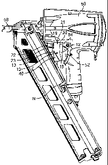
[0003] Pneumatic tools are becoming increasingly common in many
industries, including
the construction industry. Examples of pneumatic tools include pneumatic
nailers, jackhammers, riveters,
staplers, and the like. The operation of most pneumatically-operated tools is
relatively simple:
compressed air flows through a tube into the housing of the pneumatic tool and
the pressure of the
compressed air is used to force movement of a piston or other mechanism in the
tool to do work.
[0004] A pneumatic tool typically is activated by depressing a
trigger to drive the nails,
rivets, staples, or similar fasteners from the tool. In automated
applications, actuation devices are used
to depress the trigger of the pneumatic tool. These actuation devices, though,
can be large and involve
complicated assembly. For example, known actuation devices use elaborate
pulley systems; these
devices, however, can be heavy and sometimes interfere with the use of the
tool. In cases where the tool
is relatively small, no comparably small automatic actuation devices are
available.
[00051 Accordingly, there is a need for a simple, easy to use,
lightweight pneumatic tool
actuation device. Desirably, such an actuator is made of a lightweight
material and is able to withstand
fast, repetitive use. More desirably, such an actuator is readily made and
usable, and has a high degree
of integrity at minimal cost.
CA 02742591 2011-05-03
WO 2010/053640 PCT/US2009/059183
2
BRIEF SUMMARY OF THE INVENTION
[0006] The present
invention is directed to a pneumatic tool actuation
device. The device comprises a housing configured to attach to a pneumatic
tool, a
piston slidably moveable within a drive chamber formed within the housing, and
an 0-
ring disposed in a groove formed in the piston and forming a seal between the
piston
and the drive chamber. The housing has a gas inlet/outlet which is configured
to be
connected to a hose through which a gas travels and enters the drive chamber
to
slidably move the piston within the drive chamber. The movement of the piston
directly
actuates a trigger valve pin on the pneumatic tool.
BRIEF DESCRIPTION OF THE SEVERAL VIEWS OF THE DRAWINGS
[0007] The benefits and
advantages of the present invention will become
more readily apparent to those of ordinary skill in the relevant art after
reviewing the
following detailed description and accompanying drawings, wherein:
[0008] FIG. 1 is a left
side view of the pneumatic tool actuation device
in the preferred embodiment of the present invention shown attached to a
pneumatic
tool;
[0009] FIG. 2 is a right
side view of the actuation device of the present
invention attached to a pneumatic tool;
[0010] FIG. 3 is a bottom
perspective view of the actuation device of the
present invention attached to a pneumatic tool;
[0011] FIG. 4 is a top
perspective view of the actuation device of the
present invention;
[0012] FIGS. 4A and 4B are
perspective views of the actuation device
of the present invention;
[0013] FIG. 5 is a top plan
view of the actuation device of the present
invention;
[0014] FIG. 6 is a right
side plan view of the actuation device of the
present invention;
CA 02742591 2013-05-08
=
3
[00151 FIGS. 6A and 6B are right and left side views, respectively,
of the actuation
device of the present invention;
[00161 FIG. 7 is a side view of the piston element of the present
invention;
[00171 FIG. 8 is a perspective view of first and second embodiments
of the activation
device in accordance with the present invention;
[00181 FIG. 9 is a side view of the second embodiment of the
activation device illustrated
in FIG. 8;
[00191 FIG. 10 is a top view of the second embodiment of the
activation device
illustrated in FIG. 8;
[00201 FIG. 11 is a side view of the second embodiment of the
activation device
illustrated in FIG. 8 mounted to a small tool;
[00211 FIG. 12 is a perspective view of the piston element of the
second embodiment
of the actuation device actuating the trigger valve pin on a pneumatic tool;
[0022] FIGS. 13-15 are various views of the second embodiment of the
actuation device
showing interior portions in phantom lines.
DETAILED DESCRIPTION OF THE INVENTION
[00231 While the present invention is susceptible of embodiment in
various forms, there
is shown in the drawings and will hereinafter be described a presently
preferred embodiment with the
understanding that the present disclosure is to be considered an
exemplification of the invention and is
not intended to limit the invention to the specific embodiment illustrated.
[00241 It should be further understood that the title of this
section of this specification,
namely, "Detailed Description Of The Invention," relates to a preferred format
for patent applications,
and does not imply, nor should be inferred to limit the subject matter
disclosed herein.
CA 02742591 2013-05-08
4
[0025] In the present disclosure, the words "a" or "an" are to be
taken to include both
the singular and the plural. Conversely, any reference to plural items shall,
where appropriate, include
the singular.
100261 The present invention pertains to an actuation device or
actuator configured to
depress a trigger on a pneumatically driven tool as illustrated in the
figures. The actuator can be used
on a pneumatic nailer as shown; however, it is also contemplated that the
actuator can be used on other
pneumatic tools and such uses should be considered to be within the scope of
this invention. The actuator
is configured to depress a trigger on the pneumatic tool when the actuator is
actuated, thereby actuating
the pneumatic tool.
[0027] In a broad aspect, the invention provides a pneumatic tool
actuation device for
use in an associated pneumatic tool having a naked trigger valve pin
comprising a housing having a piston
drive chamber and an air inlet chamber formed therein, the housing having a
fastener receiving opening,
wherein the fastener receiving opening is configured to attach the actuation
device to the pneumatic tool.
A piston is disposed within the piston drive chamber and configured to
slidably move within the piston
drive chamber. The piston has a piston head and a support plate, a shaft and
an annular groove formed
between the piston head and the support plate, and an 0-ring. The 0-ring is
disposed in the annular
groove and the 0-ring forms a seal between the piston and the piston drive
chamber. Movement of the
piston actuates the trigger valve pin directly, without contact with a trigger
of the pneumatic tool and the
piston drive chamber and the air inlet chamber are contiguous.
[0028] Turning now to the figures and in particular FIGS. 1-6, the
actuator 10 includes
a housing 12 having a piston 14 disposed therein. The actuator housing 12 is a
one-piece unit composed
of a main body 13 and integral actuator attachment arms 22, 23 as seen in
FIGS. 5 and 6. In one
embodiment, as shown in FIG. 1, the housing 12 is configured to be used with a
pneumatic nailer, such
as a nailer available from ITW Industrial Fastening of Elgin, Illinois, an
Illinois Tool Works company.
Preferably, the housing 12 is formed of a strong, durable, lightweight
material, such as aluminum.
CA 02742591 2013-05-08
= =
4a
[0029] As the nail count in a magazine in the tool 50 is depleted, a
nail follower (nail
pusher) N moves toward the front or disbursal section of the nailer 50. Thus,
in a preferred embodiment,
the main body 13 of the housing 12 has a triangular-shaped clearance cutout 40
formed on an outer
surface of the actuator housing 12 to accommodate a follower N on a pneumatic
nailer 50.
[0030] A drive chamber 42 is formed as a cylindrical bore extending
partially through
the main body 13 of the actuator housing 12, as shown in FIGS. 4-7. A piston
14 is disposed and
slidably movable within the cylindrical drive chamber 42. The piston 14 is
made from brass in the
present embodiment, but other materials such as steel or plastics or
composites thereof are also
contemplated. The material of the piston 14 should be capable of withstanding
continuous and repetitive
strikes/stresses, as well as stresses due to friction.
CA 02742591 2011-05-03
WO 2010/053640 PCT/US2009/059183
[0031] Actuator attachment
arms 22, 23 are integral with the main body
13 of the actuator housing 12. The actuator arms 22, 23 are spaced apart,
allowing for
the attachment arms 22, 23 to straddle the trigger housing 54 of the tool 50.
[0032] The piston 14
comprises a piston head 15, a groove G, a support
plate P, and a shaft S. An 0-ring 16 is disposed in the groove G of the piston
14. The
0-ring 16 acts as a seal or gasket to prevent air from escaping up along the
sides of the
drive chamber 42, between the piston 14 and the drive chamber 42. It is
contemplated
that the material used for the 0-ring is suitable for extremes in temperature
and capable
of withstanding repetitive movement and/or vibration, such as a rubber 0-ring
as is
known in the art.
[0033] The piston head 15
is configured to extend outwardly from
actuator housing 12 through an opening formed by drive chamber 42. In its non-
actuated state, the piston head 15 is configured to lie adjacent to or in
close proximity
of the trigger 52 when the actuator 10 is attached to the pneumatic tool 50.
[0034] An air inlet chamber
34 is formed as a cylindrical bore extending
partially through the main body 13 of the actuator housing 12, contiguous with
and
generally normal to drive chamber 42. The air inlet chamber 34 is configured
to accept
and direct a pressurized gas to the drive chamber 42, as discussed below.
[0035] The actuator 10 is
attached to the pneumatic tool 50 by pins 18,
19. The pins 18, 19 attach the actuator housing 12 to the trigger housing 54
through pin
holes 20, 21 in the actuator housing 12 and through the trigger housing holes
56, 57 on
the tool 50. It is anticipated that the pneumatic tool 50 has pre-formed holes
in the
trigger housing 54 to accept pins 18. However, those skilled in the art will
recognized
that holes may need to be formed in other pneumatic tools to attach the
actuator 10 or
that other attachment methods may be required depending on the design of the
particular pneumatic tool.
[0036] Looking to FIGS. 2
through 4, the actuator 10 is shown with a
hose 26 that carries air from a compressor (not shown) to the actuator 10. The
hose 26
has two ends, a compressor end 28 that connects the hose 26 to the air
compressor, and
an actuator end 30, which comprises a brass elbow connector connecting the
hose 26 to
CA 02742591 2011-05-03
WO 2010/053640 PCT/US2009/059183
6
the actuator 10 at opening 30b formed by the air inlet chamber 34 (FIG. 6) on
the main
body 13 of the actuator housing 12.
[0037] Air from a compressor is pressurized; therefore, when a control
valve is opened, or when a signal from a control system activates, air flows
from the
compressor through the hose 26, through air inlet chamber 34 and into the
drive
chamber 42 of the actuator 10. The pressurized air in the drive chamber 42
pushes
against the support plate P of the piston 14, forcing the piston 14 to move
slidably
within the drive chamber 42 and toward the trigger 52 of the pneumatic tool
50. The
piston 14 then contacts the trigger 52 of the pneumatic tool 50 and depresses
the trigger
52, thereby actuating pneumatic tool 50.
[0038] After the pneumatic tool 50 is actuated, the air is released from
hose 26, and the trigger 52, which is spring-loaded in most pneumatic tools,
returns to
its original position, forcing the piston 14 to retract and slidably move
within the drive
chamber 42 toward the housing 12 in preparation for the next actuation. As
will be
appreciated by those skilled in the art, a shuttle valve may be used in
conjunction with
the compressor to control the flow of air to and from the actuator 10.
[0039] An alternate embodiment of a pneumatic tool actuation device
that can be used for smaller pneumatic tools is illustrated in FIGS. 8-15. In
FIG. 8, the
embodiment 10 described above is shown side-by-side with the alternate
embodiment
100.
[0040] The actuator 100 can be used for smaller devices configured for
driving staples, wires, and other like fasteners. The actuator 100 can be used
to directly
actuate a trigger valve pin. Actuator 100 is comprised of a housing 112 having
a piston
114 disposed therein. The actuator housing 112 is a one-piece unit having a
main body
113 and integral actuator attachment points 120, 122 as seen in FIG. 9.
Preferably, the
housing 112 is formed of a strong, durable, lightweight material, such as
aluminum.
[0041] In this embodiment, the relatively smaller size (as seen in FIG. 8)
of the main body 113 precludes the need for a clearance cutout to accommodate
a
follower (nail pusher) on the pneumatic nailer 150. The follower moves toward
the
front or disbursal section of the nailer 150 as the nail count in the magazine
is depleted
and easily bypasses the housing 112 of the pneumatic actuator 100.
CA 02742591 2013-05-08
7
[0042] A drive chamber 142 is formed as a cylindrical bore extending
partially through
the main body 113 of the actuator housing 112, as shown in FIGS. 13-15. A
piston 114 is disposed and
slidably movable within the cylindrical drive chamber 142. The piston 114 is
made from brass in the
present embodiment, but other materials such as steel or plastics or
composites thereof are also
contemplated. The material of the piston 114 should be capable of withstanding
continuous and repetitive
strikes/stresses as well as stresses due to friction.
[0043] Actuator attachment points 120, 122 allow the main body 113
of the actuator
housing 112 to be integrated to the pneumatic tool 150. The actuator
attachment points 120, 122 in this
embodiment are positioned in and secured to the interior of the trigger
housing 154 of the pneumatic tool
150, as shown in FIG. 11.
[0044] The piston 114 comprises a piston head, a groove, a support
plate, and a shaft
similar to or the same as previously described. As 0-ring 141 is disposed in
the groove of the piston
114. The 0-ring 141 acts as a seal or gasket to prevent air from escaping up
along the sides of the drive
chamber 142, between the piston 114 and the drive chamber 142. It is
contemplated that the material
used for the 0-ring 141 is suitable for extremes in temperature and capable of
withstanding repetitive
movement and/or vibration.
[0045] As shown in FIG. 12, the piston head 115 is configured to
extend outwardly from
the actuator housing 112 through an opening formed by drive chamber 142. In
its non-actuated state,
the piston head 115 is configured to lie adjacent to or in close proximity of
the trigger valve pin 152
when the actuator 100 is attached to the pneumatic tool 150.
[0046] As shown in FIGS. 13-15, an air inlet chamber 134 is formed
as a cylindrical
bore extending partially through the main body 113 of the actuator housing
112, contiguous with and
generally normal to the drive chamber 142, and is configured to accept and
direct a pressurized gas via
hose 126 to the drive chamber 142.
[0047] The actuator 100 is attached to the pneumatic tool 150 by
pins 118, 119. The
pins 118, 119 attach the actuator housing 12 to the trigger housing 154
through fastener receiving
openings or pin holes 120, 122 in the actuator housing 112 and through the
trigger housing holes 156,
157. It is anticipated that the pneumatic tool 150 has pre-formed holes in the
trigger housing 154
CA 02742591 2013-05-08
8
to accept pins 118. However, those skilled in the art will recognize that
holes may need to be formed
in other pneumatic tools to attach the actuator 100 or that other attachment
methods may be required
depending on the design of the particular pneumatic tool. In this embodiment,
the actual trigger of the
tool need not be present. The trigger valve pin may be directly actuated by
the piston.
[00481 When a control valve is opened, or when a signal from a
control system activates,
air flows from the compressor through a hose and through though the air inlet
chamber 134 and into the
drive chamber 142 of the actuator 100. The pressurized air in the drive
chamber 142 pushes against the
piston 114, forcing the piston 114 to move slidably within the drive chamber
142 and toward the trigger
valve pin 152 of the pneumatic tool 150. The piston 114 then contacts the
trigger valve pin 152 of the
pneumatic tool 150 and depresses the trigger valve pin 152, thereby actuating
pneumatic tool 150.
[00491 After the pneumatic tool 150 is actuated, the air is
released, and the trigger valve
pin 152, which is spring-loaded in most pneumatic tools, returns to its
original position, forcing the piston
114 to retract and slidably move within the drive chamber 142 toward the
housing 112 in preparation for
the next actuation. As will be appreciated by those skilled in the art, a
shuttle valve may be used in
conjunction with the compressor to control the flow of air to and from the
actuator 100.
[0050] The scope of the claims should not be limited by the
preferred embodiments set
forth in the description, but should be given the broadest interpretation
consistent with the description as
a whole.