Sélection de la langue

Search

Sommaire du brevet 2743298 

Énoncé de désistement de responsabilité concernant l'information provenant de tiers

Une partie des informations de ce site Web a été fournie par des sources externes. Le gouvernement du Canada n'assume aucune responsabilité concernant la précision, l'actualité ou la fiabilité des informations fournies par les sources externes. Les utilisateurs qui désirent employer cette information devraient consulter directement la source des informations. Le contenu fourni par les sources externes n'est pas assujetti aux exigences sur les langues officielles, la protection des renseignements personnels et l'accessibilité.

Disponibilité de l'Abrégé et des Revendications

L'apparition de différences dans le texte et l'image des Revendications et de l'Abrégé dépend du moment auquel le document est publié. Les textes des Revendications et de l'Abrégé sont affichés :

  • lorsque la demande peut être examinée par le public;
  • lorsque le brevet est émis (délivrance).
(12) Brevet: (11) CA 2743298
(54) Titre français: RECUPERATION DE LA CHALEUR UTILISEE POUR LA STERILISATION DES DECHETS BIOLOGIQUES
(54) Titre anglais: HEAT RECOVERY IN BIOWASTE STERILIZATION
Statut: Périmé et au-delà du délai pour l’annulation
Données bibliographiques
(51) Classification internationale des brevets (CIB):
  • A61L 11/00 (2006.01)
  • F28D 19/00 (2006.01)
(72) Inventeurs :
  • MATTILA, JUHA (Finlande)
(73) Titulaires :
  • STERIS EUROPE, INC. SUOMEN SIVULIIKE
(71) Demandeurs :
  • STERIS EUROPE, INC. SUOMEN SIVULIIKE (Finlande)
(74) Agent: NORTON ROSE FULBRIGHT CANADA LLP/S.E.N.C.R.L., S.R.L.
(74) Co-agent:
(45) Délivré: 2012-12-04
(22) Date de dépôt: 2011-06-15
(41) Mise à la disponibilité du public: 2012-01-02
Requête d'examen: 2011-06-15
Licence disponible: S.O.
Cédé au domaine public: S.O.
(25) Langue des documents déposés: Anglais

Traité de coopération en matière de brevets (PCT): Non

(30) Données de priorité de la demande:
Numéro de la demande Pays / territoire Date
20105757 (Finlande) 2010-07-02

Abrégés

Abrégé français

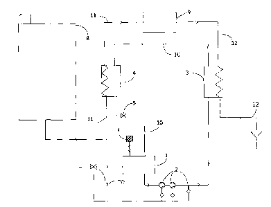
La présente invention vise une méthode de récupération de la chaleur utilisée dans un dispositif pour stériliser des déchets biologiques. Cette méthode élimine le risque de contaminer l'effluent stérilisé avec des matières biologiques non stérilisées via le système de récupération de la chaleur. En vertu de la présente invention, le circuit de récupération de la chaleur d'un dispositif permet d'acheminer la chaleur émanant du courant de l'effluent stérilisé vers le courant d'alimentation des produits biologiquement dangereux. Pour éviter toute contamination due à une fuite, il suffit de maintenir une différence de pression en tout temps afin d'empêcher les matières biologiquement dangereuses de contourner le traitement thermique et de couler en direction des matières stérilisées.


Abrégé anglais

According to the present invention a method for heat recovery in a device for the sterilization of biological material is provided. The present method eliminates the risk of contaminating the sterilized effluent with unsterilized biological material via the heat recovery system. In a device according to the invention, a heat recovery circuit is provided for transferring heat from the sterilized effluent stream to the biologically hazardous feed stream. Protection against contamination through leaks is obtained by maintaining at all times a pressure difference preventing biologically hazardous material from bypassing the heat treatment and flowing in the direction of the sterilized material.

Revendications

Note : Les revendications sont présentées dans la langue officielle dans laquelle elles ont été soumises.


6
Claims
1. A method for recovering heat in a device for the sterilization of
biological material,
comprising
- transferring heat from a sterilized effluent stream (12) to a stream (10) in
a heat recovery
circuit
- transferring heat from the stream (10) in the heat recovery circuit to a
stream of
biologically contaminated feed (11)
- while maintaining the pressure (p12) in the sterilized effluent stream (12)
higher than the
pressure (p10) in the heat recovery circuit, which is maintained higher than
the pressure
(p11) in the stream of biologically contaminated feed (11).
2. A method according to claim 1, wherein the pressure p12 in the sterilized
effluent stream
is over 6 bar, the pressure p10 in the heat recovery circuit is at minimum 1
bar and at
maximum 3 bar, and the pressure p11 in the stream of biologically contaminated
feed is 0.5
bar or less.
3. A device for the sterilization of biological material, comprising a feed
line (11) for
contaminated material, a unit (4) for heat treatment of said material and an
effluent line
(12) for sterilized material, characterized in that it is provided a heat
recovery circuit for
transferring heat from a stream in said effluent line (12) to a stream in said
feed line (11),
said heat recovery circuit including an effluent heat exchanger (3) having an
effluent side
and a heat recovery circuit side; a feed heat exchanger (4) having a feed side
and a heat
recovery circuit side; piping (10) connecting the heat recovery circuit sides
of said heat
exchangers; at least one pump (2) for circulating a liquid through said heat
recovery
circuit; and means for maintaining a pressure in the heat recovery circuit
side of the
effluent heat exchanger (3) lower than the pressure in the effluent side (12);
and means for
maintaining a pressure in the heat recovery circuit side of the feed heat
exchanger (4)
higher than the pressure in the feed side (11).

Description

Note : Les descriptions sont présentées dans la langue officielle dans laquelle elles ont été soumises.


CA 02743298 2011-06-15
Heat recovery in biowaste sterilization
The invention relates to improvement in heat recovery in a sterilization
process for
biological waste and to a device for implementing the method.
Biological waste is produced e.g. in hospitals, agricultural or biological
research and
production facilities, plasma fractionation facilities, etc. Biological wastes
produced in
such facilities cannot be directly conducted to a sewer system, as these
wastes often
contain micro-organisms, such as bacteria, viruses and other microorganisms,
which are
hazardous to humans and animals. Prior to conducting to a sewer system, such
biowaste
must first be deactivated in a treatment plant designed for this purpose. For
the treatment of
biowaste, different treatment plants have been designed in which biowaste is
sterilized
prior to conducting to the sewer system. The sterilization of biowaste can be
carried out
chemically or by means of heat. The treatment plants can operate continuously
or
batchwise.
In an article by Carl J. Carlson in Pharmaceutical Engineering, May/June 2001,
pages 70
to 82, facilities for the treatment of biowaste are described. The article
deals with biowaste
treatment facilities of different types as well as with dimensioning
principles and problems
relating thereto.
According to said article, a typical thermal continuous biowaste sterilisation
apparatus
comprises a separating unit for solid matter, a storage tank, a heating unit
and a dwell
circuit as well as a circulation circuit for circulating biowaste through said
heating unit and
said dwell circuit. According to the article, a typical continuous apparatus
comprises the
following stages: a heating stage, whereby biowaste is circulated in a heat
exchanger and
in a dwell circuit, until a temperature sufficient to kill the micro-organisms
is reached. This
is followed by an operating stage when the biowaste has reached the required
temperature
over the whole length of the heat exchanger. Thereby the treated biowaste is
conducted
through cooling equipment to a sewer system. If one or several sterilization
parameters
(temperature in the dwell circuit, pressure etc.) go outside the predetermined
value, and the
biowaste is therefore insufficiently sterilized, the process enters a hold
state, where the
biowaste is circulated through the heating unit and the dwell circuit until
the parameter or
parameters in question are again within the given limits. In case of an alarm,
the apparatus

CA 02743298 2011-06-15
2
enters the cooling mode, in which the operation of the heating unit is
stopped, and the
biowaste is recycled back to the pump feed line until the apparatus is again
in working
order. According to the article, provisions for the steam sterilization of the
parts
downstream from the storage tank should be provided, as well as provisions for
preventing
the transfer of the active biowaste to the cooling circuit. In addition, steam
sterilization of
the storage tank, the piping, venting filters, etc. should be provided in the
apparatus.
Biowaste sterilization plants are usually provided with heat exchangers for
cooling the
effluent before it enters the sewer. The heat removed from the effluent stream
is normally
not utilized for feed preheating because of the safety issues involved with
establishing a
heat transfer connection between a sterilized stream and a biologically
hazardous stream. A
leak in a heat transfer loop may cause a serious risk of contamination.
The present invention provides heat recovery from the effluent stream without
jeopardizing
the integrity of the clean, or sterilized, stream and the equipment for
handling it.
Disclosure of the invention
According to an aspect of the present invention, a method is provided for heat
recovery in
a device for the sterilization of biological material, said method eliminating
the risk of
contaminating the sterilized effluent with unsterilized biological material
via the heat
recovery system.
According to another aspect of the present invention, a device for the
sterilization of
biological material is provided comprising means for heat recovery, while
ensuring that
unsterilized biological material cannot enter the sterilized effluent via the
heat recovery
system.
In a device according to the invention, a heat recovery circuit is provided
for transferring
heat from the sterilized effluent stream to the biologically hazardous feed
stream.
Protection against contamination through leaks is obtained by maintaining at
all times a
pressure difference preventing biologically hazardous material from bypassing
the heat
treatment and flowing in the direction of the sterilized material.

CA 02743298 2011-06-15
3
Brief description of the drawing
Figure 1 is a schematic view of a device according to the invention, showing
only the
components required for the understanding of the invention.
Detailed disclosure
An advantageous embodiment of the invention is described below with reference
to the
accompanying drawing.
The figure 1 shows a biowaste treatment apparatus according to the invention.
The main
components provided in the main line of the treatment apparatus in the flow
direction of a
biowaste-containing liquid are a storage tank 8 for the biowaste, a
contaminated-feed line
11, a decontamination unit 9 and an exit line 12 for sterilized effluent. The
decontamination unit comprises an appropriate number of pumps, heat
exchangers,
temperature and pressure sensors, valves and piping, none of which are shown
but can be
arranged as disclosed in e.g. EP 1 440 040. From the decontamination unit 9, a
line 12 for
sterilized effluent leads to the sewer.
In accordance with the present invention, the treatment apparatus comprises a
heat
recovery circuit comprising a break tank 1; at least one circulation pump 2;
at least one
heat recovery exchanger or effluent heat exchanger 3 for transferring heat
from the effluent
line 12 to the heat recovery circuit; at least one heat delivery exchanger or
feed heat
exchanger 4 for transferring heat from the heat recovery circuit to the
contaminated-feed
line 11; and interconnecting piping 10. The reference numeral 10 can be used
in the
following to refer either to the interconnecting piping or to the stream
within the heat
recovery circuit.
According to the invention, the pressure p12 in the sterilized effluent line
12 is at all times
higher than the pressure plo in the heat recovery circuit, and the pressure p
1 o in the heat
recovery circuit is at all times higher than the pressure p11 in the
contaminated-feed line 11.
Thus, any movement of contaminated feed towards the sterilized effluent
conduit is made
impossible.
In principal the sterilization operation of biological material comprises
three process
stages; heating stage or start-up, operating i.e. sterilization stage and
shutting down. In the

CA 02743298 2011-06-15
4
context of this invention the term "all times" means these three process
stages; start-up,
sterilization and shut-down. In case one or several sterilization parameters
go outside the
predetermined value and the biowaste is therefore insufficiently sterilized,
the process
enters a hold state. During the operating stage the treated biowaste is
conducted through
cooling equipment to a sewer system. The most critical process stages as
regards the risk of
contamination through leaks, between the contaminated and sterilized water,
are the start
up and shut down. Therefore special care is taken during these stages. The
sterilization
process is started up as a closed system, during which the operability and
safety of the
process is ensured, especially the sufficiency of the decontamination and the
critical
pressures (p10, p11 and p12) are determined and adjusted. The arrangement
according to the
present invention, shown in Figure 1, i.e. the independent pressurized and
pressure
controlled heat transfer water loop ensures that the incoming contaminated
feed cannot be
in contact, not even indirectly, with the decontaminated effluent.
Additionally, such
pressure differential situations between these media are also avoided during
the
decontamination process. Further, the internal circulation (water loop) is
protected by the
pressure switch and pressure alarm and e.g. HEPA filter in the break tank 1.
Water enters the heat recovery circulation process from the break tank 1,
which is
preferably at atmospheric pressure. Air exchange from the break tank 1 is
protected by, for
example, a HEPA filter 6. The circulation pump 2a raises the pressure in the
initial part of
the heat recovery circuit to, for example, 3 bar. As shown in the figure, a
backup pump 2b
is provided in case the first pump would fail or not produce the required
pressure. The
circulation pump 2a and the back-up pump 2b are shown in figure 1 with
reference number
2. Preferably, the pumps are multistage centrifugal pumps, e.g. displacement
pumps.
Preferably, only one pump is used at a time.
In the heat recovery exchanger 3, having an effluent side and a heat recovery
circuit side,
the pressure P12 on the effluent side 12 is kept at a higher level than in the
heat recovery
circuit, for example at 7 bar at the inlet, decreasing to for example 6 bar at
the outlet
assuming the pressure drop across the exchanger is of the order 1 bar.
Correspondingly, the
pressure p10 on the heat recovery circuit side decreases to 2 bar in this
example. The
pressure P12 on the effluent side 12 is typically kept at a minimum of 6 bar.
The pressure
p10 on the heat recovery circuit side is kept at a minimum of 1 bar and at a
maximum of 3

CA 02743298 2011-06-15
bar. Any internal leak in the exchanger would lead to sterilized effluent
entering the heat
recovery circuit, but not to heat recovery circuit water entering the
sterilized effluent line.
In the heat delivery exchanger 4, having a feed side and a heat recovery
circuit side, the
5 pressure plo in the recovery circuit typically falls below 2 bar but is kept
at a minimum of 1
bar, while the pressure p> > on the side of the contaminated feed is no higher
than 0.5 bar.
Thus, at all times, the pressure p10 in the heat recovery circuit is higher
than the pressure
p> > in the contaminated feed line 11 and no contaminated feed will enter the
heat recovery
circuit in case of a leak within the heat delivery exchanger 4.
The pressure and flow rate in the heat recovery loop are determined by a fixed
orifice 5, in
addition to the pressure drops characteristic to the heat exchangers. Thus,
when the
performance of the pump 2 is according to specifications, the various pressure
ratios within
the heat recovery circuit remain permanent. After passing the fixed orifice 5,
the water in
the heat recovery circuit returns to the break tank 1. The water level of the
break tank is
maintained by means of valve 7, connected to a level sensor. If the pressure
in the heat
recovery circuit falls below the set lower limit e.g. 0.8 bar, the pressure
switch will alert
and stop the process. Thus, the means for maintaining the pressure in the heat
recovery
circuit side of the effluent heat exchanger (3) lower than the pressure in the
effluent side
(12); and the means for maintaining a pressure in the heat recovery circuit
side of the feed
heat exchanger (4) higher than the pressure in the feed side (11) comprise the
pump (2),
which induces the pressure, and the fixed orifice (5), which is used to
determine the stream
and by that way the counter pressure of the system; thus no other adjusting
devices are
needed.
The above described method for heat recovery in biowaste sterilization can be
applied to
both continuously and batchwise operating sterilization processes.
In the above example, water is used as a heat transfer medium, but other heat
transfer
liquids are also possible. An indicator substance may be added to the heat
recovery circuit
to reveal leaks for example by a color change in the effluent.

Dessin représentatif
Une figure unique qui représente un dessin illustrant l'invention.
États administratifs

2024-08-01 : Dans le cadre de la transition vers les Brevets de nouvelle génération (BNG), la base de données sur les brevets canadiens (BDBC) contient désormais un Historique d'événement plus détaillé, qui reproduit le Journal des événements de notre nouvelle solution interne.

Veuillez noter que les événements débutant par « Inactive : » se réfèrent à des événements qui ne sont plus utilisés dans notre nouvelle solution interne.

Pour une meilleure compréhension de l'état de la demande ou brevet qui figure sur cette page, la rubrique Mise en garde , et les descriptions de Brevet , Historique d'événement , Taxes périodiques et Historique des paiements devraient être consultées.

Historique d'événement

Description Date
Le délai pour l'annulation est expiré 2020-08-31
Inactive : COVID 19 - Délai prolongé 2020-08-19
Inactive : COVID 19 - Délai prolongé 2020-08-06
Inactive : COVID 19 - Délai prolongé 2020-07-16
Inactive : COVID 19 - Délai prolongé 2020-07-02
Inactive : COVID 19 - Délai prolongé 2020-06-10
Représentant commun nommé 2019-10-30
Lettre envoyée 2019-06-17
Accordé par délivrance 2012-12-04
Inactive : Page couverture publiée 2012-12-03
Préoctroi 2012-09-12
Inactive : Taxe finale reçue 2012-09-12
Lettre envoyée 2012-08-15
Un avis d'acceptation est envoyé 2012-08-15
Inactive : Approuvée aux fins d'acceptation (AFA) 2012-08-09
Demande publiée (accessible au public) 2012-01-02
Inactive : Page couverture publiée 2012-01-01
Inactive : CIB attribuée 2011-10-07
Inactive : CIB en 1re position 2011-10-07
Inactive : CIB attribuée 2011-08-05
Inactive : Certificat de dépôt - RE (Anglais) 2011-06-30
Lettre envoyée 2011-06-30
Demande reçue - nationale ordinaire 2011-06-30
Modification reçue - modification volontaire 2011-06-15
Exigences pour une requête d'examen - jugée conforme 2011-06-15
Toutes les exigences pour l'examen - jugée conforme 2011-06-15

Historique d'abandonnement

Il n'y a pas d'historique d'abandonnement

Historique des taxes

Type de taxes Anniversaire Échéance Date payée
Taxe pour le dépôt - générale 2011-06-15
Requête d'examen - générale 2011-06-15
Taxe finale - générale 2012-09-12
TM (brevet, 2e anniv.) - générale 2013-06-17 2013-05-17
TM (brevet, 3e anniv.) - générale 2014-06-16 2014-06-09
TM (brevet, 4e anniv.) - générale 2015-06-15 2015-06-08
TM (brevet, 5e anniv.) - générale 2016-06-15 2016-06-13
TM (brevet, 6e anniv.) - générale 2017-06-15 2017-06-12
TM (brevet, 7e anniv.) - générale 2018-06-15 2018-06-11
Titulaires au dossier

Les titulaires actuels et antérieures au dossier sont affichés en ordre alphabétique.

Titulaires actuels au dossier
STERIS EUROPE, INC. SUOMEN SIVULIIKE
Titulaires antérieures au dossier
JUHA MATTILA
Les propriétaires antérieurs qui ne figurent pas dans la liste des « Propriétaires au dossier » apparaîtront dans d'autres documents au dossier.
Documents

Pour visionner les fichiers sélectionnés, entrer le code reCAPTCHA :


Pour visualiser une image, cliquer sur un lien dans la colonne description du document. Pour télécharger l'image (les images), cliquer l'une ou plusieurs cases à cocher dans la première colonne et ensuite cliquer sur le bouton "Télécharger sélection en format PDF (archive Zip)" ou le bouton "Télécharger sélection (en un fichier PDF fusionné)".

Liste des documents de brevet publiés et non publiés sur la BDBC .

Si vous avez des difficultés à accéder au contenu, veuillez communiquer avec le Centre de services à la clientèle au 1-866-997-1936, ou envoyer un courriel au Centre de service à la clientèle de l'OPIC.


Description du
Document 
Date
(aaaa-mm-jj) 
Nombre de pages   Taille de l'image (Ko) 
Description 2011-06-14 5 251
Abrégé 2011-06-14 1 16
Revendications 2011-06-14 1 40
Dessins 2011-06-14 1 8
Dessin représentatif 2011-10-25 1 5
Dessin représentatif 2012-11-07 1 5
Accusé de réception de la requête d'examen 2011-06-29 1 178
Certificat de dépôt (anglais) 2011-06-29 1 157
Avis du commissaire - Demande jugée acceptable 2012-08-14 1 162
Rappel de taxe de maintien due 2013-02-17 1 112
Avis concernant la taxe de maintien 2019-07-28 1 183
Correspondance 2012-09-11 2 66