Note : Les descriptions sont présentées dans la langue officielle dans laquelle elles ont été soumises.
CA 02743798 2011-05-16
WO 2010/055435 PCT/1B2009/054831
1
APPLIANCE FOR DELIVERING LIQUID TO A GAS STREAM
FOR CREATING DROPLETS IN A DENTAL CLEANER
This invention relates generally to liquid droplet cleaning systems for dental
cleaning, and more specifically concerns a system for delivering liquid into a
fast-moving gas
stream to create the liquid droplets.
In general, cleaning of dental (teeth) surfaces with a stream of high-velocity
liquid droplets is known. Such systems are particularly useful for cleaning of
interproximal
spaces. One system for generating the liquid droplets involves merging liquid
flowing from
a reservoir into a fast-moving gas stream, such as provided by a source of
compressed gas.
Dental appliances using such systems are activated by a user operating a
button or the like,
releasing successive bursts of compressed gas, which results in a high
velocity gas stream.
When this high velocity gas stream comes into contact with a flow of liquid
from the
reservoir, liquid droplets are produced.
The velocity and size of the droplets can vary, but typically the droplets
will
have a size in the range of 5-500 microns, and a velocity within a range of 10-
200 meters per
second. The velocity of the gas stream will also vary; however, a typical
range would be
30-600 meters per second. In many cases, liquid is drawn from the liquid
reservoir and
delivered into the gas stream by a mechanism separate from the flow of gas
itself. This
results in a higher-cost appliance. It is desirable to have an appliance which
produces liquid
droplets for cleaning where multiple functions, including the liquid flow and
the creation of
droplets, can be accomplished by a single, relatively simple system.
Accordingly the dental cleaning apparatus using liquid droplets, comprises:
an appliance body, including a nozzle assembly with a pathway through which a
stream of
gas is directed and one or more nozzle exit orifices; a source of compressed
gas; a reservoir
for liquid; and one or more liquid connecting pathways from the liquid
reservoir through
which liquid in the reservoir can be moved into the stream of gas in the
nozzle pathway,
wherein the liquid connecting pathways are so configured and have an exit
point relative to
the stream of gas through the nozzle pathway, that gas moving through the
nozzle pathway
draws liquid from the liquid reservoir into the stream of gas, resulting in
the creation of liquid
droplets which then move out through the exit orifice toward the dental
regions to be cleaned.
CA 02743798 2016-05-02
64869-1582
la
According to one aspect of the present invention, there is provided a dental
cleaning apparatus using liquid droplets, comprising: an appliance body
including a nozzle
assembly with an interior pathway through which a stream of gas is directed,
and one or more
nozzle exit orifices; a source of compressed gas; a reservoir for liquid; a
liquid chamber
separate from the nozzle assembly and one or more connecting lines between the
reservoir for
liquid and the liquid chamber; and one or more liquid connecting pathways
between the liquid
chamber and the nozzle assembly interior pathway or from the liquid chamber
into the stream
of gas in the nozzle assembly, wherein the one or more liquid connecting
pathways are so
configured and have an exit point in the nozzle assembly that gas moving
through the nozzle
assembly interior pathway draws liquid from the liquid reservoir into the
liquid chamber and
from there into the stream of gas, resulting in the creation of liquid
droplets which then move
out through the at least one nozzle exit orifice toward the dental regions to
be cleaned,
wherein the appliance body includes a base portion containing the liquid
reservoir and the
source of compressed gas and wherein the liquid chamber defines a sleeve
including a wall
portion and a central open portion, the wall portion having a plurality of
longitudinal openings
therethrough, wherein liquid is drawn from the liquid reservoir into the
longitudinal openings
by differential pressure created by a flow of gas through the central open
portion of the sleeve.
CA 02743798 2011-05-16
WO 2010/055435 PCT/1B2009/054831
2
Figure 1 is a simple schematic view of one embodiment of the present
invention.
Figure 2 is a schematic view of another embodiment of the present invention
Figure 2A is a schematic view of a portion of the embodiment of Figure 2.
Figure 2 Figure 3 is a cross-sectional view of still another embodiment of the
present invention.
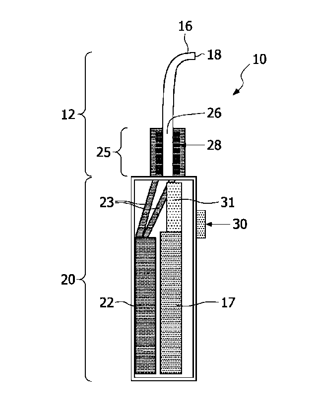
Figure 1 shows a first embodiment of an interdental cleaner with a passive
liquid delivery system. The interdental cleaner, shown generally at 10,
includes a nozzle
assembly 12 through which fast-moving gas is directed. The appliance includes
a power
source 17. The gas in the embodiment shown is compressed gas, usually from a
cylinder
source thereof. Gas volume ranges from 40-650 mm3 at a pressure between 20-900
psi. The
nozzle 12 can be shaped at its proximal end portion 16, such as a curve as
shown, so as to
more conveniently fit into the mouth of a user. The nozzle 12 ends at an exit
aperture or
apertures 18. Typically, the nozzle opening will be 0.5-2 mm in diameter.
Positioned in a
base portion 20 of the cleaning appliance assembly is a liquid reservoir
member 22, for water
or other liquid, including dentifrices. Liquid reservoir 22 is connected by
liquid lines 23-23
to a liquid chamber assembly 25 positioned around a lower end portion of
nozzle 12. The
liquid chamber assembly 25 can have various configurations; for instance, it
could be a single
member, a plurality of members or can substantially surround the nozzle 12.
The length of
the liquid reservoir can vary, but typically will be in the range of 2-30 mm.
The liquid chamber assembly includes a plurality of capillary tubes 28,
generally positioned horizontally, which connect the liquid chamber assembly
25 to the
interior 26 of the nozzle. The capillary tubes 28 will vary in size between
0.25-1 mm in
diameter. There could be a single capillary opening or a plurality thereof,
all connecting the
liquid chamber assembly to the interior 26 of the nozzle. The size of the
capillaries must be
sufficient to enable liquid to get through during operation of the appliance,
but narrow
enough to prevent the liquid from leaking out into the nozzle when not in use.
In operation, a single burst of gas will be produced, in response to the
operation by the user, of a button 30 or the like, which allows a burst of gas
from a source 31
thereof to move into the interior 26 of the nozzle. The movement of gas in the
nozzle draws
liquid present in the capillaries 28 into the interior 26 of the nozzle.
CA 02743798 2011-05-16
WO 2010/055435 PCT/1B2009/054831
3
As the gas moves through the nozzle, past the capillary tube openings, liquid
moves into the interior of the nozzle. Typically, approximately 0.02-0.20 ml
of liquid will be
drawn into interior 26 of the nozzle for a single burst of gas from source 31.
Contact between
the liquid entering the nozzle from the capillaries with the fast-flowing gas
stream will result
in the creation of liquid droplets, which move through the forward end of the
nozzle and out
exit opening 18. Sufficient liquid is drawn from the liquid reservoir with
each burst of gas to
produce an effective cleansing action on the teeth by the liquid droplets.
The advantage to the arrangement of Figure 1 is that the delivery of liquid to
the gas stream is passive, i.e. there is no separate structure or mechanism
for moving liquid
from the liquid reservoir into the gas stream other than by the movement of
the gas stream
itself through the nozzle, with liquid moving into the nozzle by capillary
action.
Figure 2 shows another passive fluid-delivery interdental system utilizing
capillary action. In this arrangement, the appliance includes a base or body
portion 32 in
which is positioned a liquid reservoir 33. The liquid reservoir in one
embodiment is a
flexible membrane which allows the reservoir to change volume as liquid is
moved from the
reservoir into the nozzle portion of the appliance. Also positioned in base
portion 32 is a
source of compressed gas 34, e.g. a cylinder of CO2 and a power source 35.
Positioned within a mid-portion of the appliance is a hollow sleeve member
36, shown in more detail in Figure 2A. Sleeve member 36 in the embodiment
shown fits in a
fluid-tight relationship within the appliance, with a diameter within the
range of 1-3 mm and
a length of 1-6 mm. The sleeve has a wall thickness of approximately 0.2-1.2
mm.
Positioned lengthwise through the sleeve wall is a series of capillary
openings 38-38 which,
like the previous embodiment, can be within the range of 0.1-1 mm in diameter.
Alternatively, there could be a single capillary, although multiple capillary
openings are
preferred, spaced evenly around the circumference of the sleeve. The spacing
can be varied,
however. Extending forward from the mid-portion of the appliance is a nozzle
portion 39,
typically curved at its proximal region, to readily fit within the mouth. The
nozzle terminates
in an exit opening 42 having a diameter of 0.5-2 mm.
The user will initiate operation of the appliance by a button switch 38 or the
like to actuate bursts of CO2 gas from gas cylinder 34. The resulting gas flow
through the
open center 43 of sleeve 36 will create a gas flow in nozzle 39, producing a
pressure
differential within the appliance and pulling liquid from reservoir 33. When
the liquid
CA 02743798 2011-05-16
WO 2010/055435 PCT/1B2009/054831
4
contacts the fast-moving gas, typically moving in the range of 30-60 m/s,
liquid droplets are
produced, and then accelerated out through exit opening 42 of the nozzle. The
droplets, as
with the above embodiment, will typically have a size range of 5-500 microns,
and a velocity
in the range of 10-200 m/s.
Although a compressed CO2 source for the gas stream is shown, it should be
understood that other means for producing the gas flow are possible, including
a
piston/cylinder arrangement or other means, such as a pump to compress air
into a valve
which is then released, as well as other types of gas, such as nitrogen or
air.
The embodiments of both Figures 1 and 2 can typically be made from a plastic
material such as a polycarbonate, although other materials can be used.
Figure 3 shows another embodiment of the appliance, referred to generally at
48, which includes an appliance chamber 50. Chamber 50 has a typical diameter
of
approximately 20 mm, which can be varied, and a length which can vary within
the range of
2-25 mm. Positioned within the chamber 50 is a plunger head portion 52 of a
plunger
assembly, the plunger head portion positioned in a generally fluid-tight
arrangement with the
internal surface of the chamber 50. A plunger arm 53 extends from a rear end
of the plunger
head out through a rear opening in chamber 50. The head plunger can move
through
substantially the length of the chamber. A liquid reservoir 54 is connected by
a line 55 to the
vicinity of the forward end of chamber 50. A check valve 57 is positioned in
the connecting
line 55, permitting a flow of liquid in one direction only, i.e. from the
reservoir 54 to the
chamber 50.
To the rear of chamber 50 in the appliance is a drive assembly 56, which
includes a battery 58, as well as control elements 59 and a display 60.
Battery 58 powers a
motor 61 which drives a drive member 62 which is part of the plunger assembly
and is
connected to plunger arm 53.
Extending from forward end 62 of chamber 50 is a nozzle 66 which is shaped
conveniently to fit within the mouth of a user for dental cleaning. In the
embodiment shown,
the nozzle is slightly curved. At the distal end of nozzle 66 is an exit
opening 68, through
which liquid droplets created by action of the gas stream move.
Extending into chamber 50 near the forward end 62 thereof is an air inlet line
70 for entry of atmospheric air. Air inlet line 70 includes a one-way check
valve 71, which
CA 02743798 2015-08-18
,
' 64869-1582
allows air to proceed only into the chamber. Alternatively, air under some
small amount of
pressure could be used as well. Positioned at the forward end of chamber 50 at
the entrance to
the nozzle is a disc member 76 having a number of openings therein. The
openings will vary
from 0.25-5 mm in diameter. There is also a one-way check valve illustrated
generally at 75
5 between chamber 50 and disc member 76, to prevent air from moving back
into the chamber.
In operation, the plunger assembly, including the plunger head, is first
withdrawn toward the rear of chamber 50 by action of motor 60, which results
in liquid from
reservoir 54 being drawn into the chamber and air being drawn into the chamber
through inlet
70. Approximately 0.25-2 ml of liquid is drawn from the reservoir upon
actuation of the
appliance. The plunger is then actuated in the opposing direction to force
liquid and air in the
chamber through the openings in disc member 76. This action creates droplets
at the proximal
(base) end of the nozzle 12. The disc 76 can be positioned at the base end of
the nozzle or
further along the nozzle. The gas pressure created by the action of the
plunger also
accelerates the droplets once they have been created through the nozzle and
out the exit
opening 68.
Accordingly, several embodiments of a dental appliance have been disclosed
which produce a spray of liquid droplets for use in interdental cleaning,
using passive
arrangements to draw liquid from a liquid reservoir and to form liquid
droplets of desirable
size and velocity.
Although a preferred embodiment of the invention has been disclosed for
purposes of illustration, it should be understood that various changes,
modifications and
substitutions may be incorporated in the embodiment without departing from the
scope of the
invention which is defined by the claims which follow.