Note : Les descriptions sont présentées dans la langue officielle dans laquelle elles ont été soumises.
CA 02743973 2011-05-17
WO 2010/057914 PCT/EP2009/065383
-1-
HARD DISC DRIVE COUNTER-VIBRATION SYSTEM
The present invention relates generally to disc drives storage devices,
and more particularly to a storage device counter-vibration system.
A hard disc drive (HDD) is a non-volatile storage device which may store
digital data. HDDs are most commonly used in personal and laptop computers,
as well as other electronic devices, such as digital video recorders (DVRs),
cell
phones, personal digital assistants, digital cameras, home video game
consoles and digital audio devices. These devices utilize the HDD to store and
retrieve digital information during operation of the devices. Generally, the
HDD
of an electronic device is contained within the device for ease of use and
access to the digital information.
To access or store digital information, the HDD may read or write to a
rotating magnetic platter using an HDD head. However, many HDDs have an
imperfect platter balance, resulting in a rotational vibration or gyration in
the
HDD as the platter spins. For example, an imbalanced platter assembly
spinning at 5400 rotations per minute (rpm) may cause a rotational vibration
or
gyration of the HDD unit at 90 hertz (Hz). Similarly, an imbalanced assembly
spinning at 7200 rpm may vibrate the HDD unit at 120 Hz. This mechanical
movement may be transferred through the case of the HDD to the electronic
device itself, resulting in a vibration-induced noise associated with the
device.
For electronic devices intended for noiseless or quiet environments, such as a
set-top box of a television system, the vibration or gyration of the HDD
within
the electronic device may produce an unintended acoustic annoyance.
To counteract the vibration or gyration of an imbalanced HDD module,
manufacturers have developed techniques in an attempt to absorb the
rotational vibration or gyration of an imbalanced HDD module. One common
solution places a series of soft grommets between the HDD and a mounting
bracket to absorb vibration or gyration and prevent it from being transferred
to
the device chassis. However, the extreme softness of grommets capable of
absorbing 90-120 Hz makes them vulnerable to damage if the HDD is ever
dropped or knocked.
CA 02743973 2011-05-17
WO 2010/057914 PCT/EP2009/065383
-2-
The invention seeks to provide a method and system for absorbing
rotational vibration of an imbalanced platter assembly of a HDD module that
allows for more durability during movement of the device.
According to a first aspect of the present invention there is provided a
storage device mounting assembly comprising: a mounting frame defining an
upper surface and a lower surface, the upper surface arranged to couple to a
storage device; at least one upper concave surface coupled to the mounting
frame, the upper concave surface oriented away from the mounting frame; at
least one sphere; and at least one lower concave surface oriented at least
partially beneath the at least one upper concave surface, wherein the at least
one sphere is oriented between the at least one upper concave surface and the
at least one lower concave surface such that the at least one sphere is at
least
partially enclosed within the at least one upper concave surface and the at
least
one lower concave surface and supports the at least one upper concave
surface.
Preferably, a mounting bracket is coupled to the at least one lower
concave surface.
In an embodiment, a cover is releasably coupled to the mounting
bracket, such that the cover and the mounting bracket form a box-like
structure,
and the hard disc drive is encased within the box-like structure.
Preferably, at least one bumper assembly is coupled to an inside surface
of the cover, the at least one bumper assembly cushioning the storage device
from impacting the inside surface of the cover.
The storage mounting assembly may further comprise a snap device
releasably coupled to the mounting frame.
In an embodiment, the assembly comprises three additional upper
concave surfaces coupled to the mounting frame; three additional spheres; and
three additional lower concave surfaces such that each upper concave surface
is associated with one of the lower concave surfaces and a sphere is oriented
between the associated upper and lower concave surfaces.
CA 02743973 2011-05-17
WO 2010/057914 PCT/EP2009/065383
-3-
The four upper concave surfaces may be located at four comers of the
mounting frame.
Preferably, the or each sphere is constructed from a vibration absorption
material.
The present invention also extends to an apparatus for absorbing
vibrations of a storage device comprising: a lower mounting frame coupled to a
bottom surface of a storage device; an upper mounting frame coupled to a top
surface of the storage device; and at least one vibration-absorbing assembly
comprising: a first concave surface coupled to the lower mounting frame or the
upper mounting frame; a sphere; and a second concave surface coupled to a
storage device housing, wherein the sphere is oriented between the first
concave surface and the second concave surface such that the sphere is at
least partially enclosed within the first concave surface and the second
concave
surface.
In an embodiment, the apparatus further comprises a cover; and a
mounting bracket configured to mount the storage device in an electronic
device, the cover being releasably coupled to the mounting bracket, such that
the cover and the mounting bracket form a box-like structure encasing the
storage device within the box-like structure.
Preferably, at least four upper vibration-absorbing assemblies and four
lower vibration-absorbing assemblies support the storage device.
The second concave surface of each of the upper vibration-absorbing
assemblies may be coupled to the upper mounting frame, and the second
concave surface of each of the lower vibration-absorbing assemblies is coupled
to the lower mounting frame.
In an embodiment, the first concave surface of each of the upper
vibration-absorbing assemblies is coupled to the cover and the first concave
surface of each of the lower vibration-absorbing assemblies is coupled to the
mounting bracket, such that the four upper vibration-absorbing assemblies and
CA 02743973 2011-05-17
WO 2010/057914 PCT/EP2009/065383
-4-
four lower vibration-absorbing assemblies absorb the vibrations of the storage
device.
Preferably, the sphere is constructed from an elastomer gel material.
The apparatus may further comprise at least one bumper assembly
coupled to the inside surface of the cover, the at least one bumper assembly
configured to cushion the storage device from impacting the inside surface of
the cover.
According to a further aspect of the invention there is provided a method
for absorbing vibrations of a storage device comprising: mounting the storage
device on a mounting frame, the mounting frame including a first concave
surface oriented away from the storage device; orienting the first concave
surface over a sphere constructed of vibration-absorbing material; orienting
the
sphere within a second concave surface, the second concave surface
associated with a mounting bracket, such that the sphere is at least partially
enclosed within the first concave surface and the second concave surface and
supports the mounting bracket.
The method may further comprise encasing the storage device within a
box-like structure, the box-like structure comprising a top piece and the
mounting bracket.
Preferably, vibrations of the hard disc drive are translated through the
first concave surface to the sphere, such that the sphere at least partially
absorbs the vibrations.
In an embodiment, at least one bumper device is attached to an inside
surface of the top piece, the at least one bumper device being arranged to
cushion the storage device from impacting the inside surface of the top piece.
Preferably, the sphere is constructed from an elastomer gel material.
Embodiments of the present invention will hereinafter be described, by
way of example, with reference to the accompanying drawings, in which:
CA 02743973 2011-05-17
WO 2010/057914 PCT/EP2009/065383
-5-
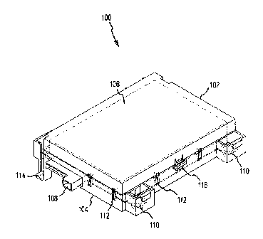
Figure 1 depicts an isometric view of an embodiment of a hard drive
disc housing assembly including a counter-vibration mounting assembly,
Figure 2 shows a front view of the embodiment of Figure 1,
Figure 3 shows a side view of the embodiment of Figure 1,
Figure 4 shows a top view of the embodiment of Figure 1,
Figure 5 shows a bottom view of the embodiment of Figure 1, and
Figure 6 shows a side view of a second embodiment of a hard drive disc
housing assembly including a counter-vibration mounting assembly.
One implementation of the present invention may take the form of a
system for a storage device counter-vibration device that may absorb
rotational
vibration or gyration of the hard disc drive module or other storage device.
This
mounting device may incorporate at least one soft, plastic sphere and a pair
of
concave dished surfaces, configured to face each other and maintain the
sphere between them. The sphere of the counter-vibration assembly may
support the hard disc drive (HDD) while the weight of the HDD may align the
dishes with each other and over the sphere. In this manner, the sphere may
act as a spring and allow the HDD to vibrate or gyrate thus minimizing the
physical movement transmittance to the rest of the HDD assembly or electronic
device. While the examples and figures below describe a counter-vibration
mechanism in relation to a HDD, it should be appreciated that the described
embodiments may provide vibration absorption for any data storage device that
may vibrate or gyrate during operation.
Figure 1 shows an isometric view of an embodiment of a hard drive disc
housing assembly which includes a counter-vibration mounting system
incorporating spheres. The housing assembly may encase an HDD and
include at least one sphere and concave surface to absorb the rotational
vibration or gyration of the HDD module. Further, the housing assembly may
also include bumper features to protect the HDD from damage if the assembly
is dropped or knocked. Such a structure may also act as a barrier to direct
acoustic noise generated by the HDD.
The housing assembly 100 of Figure 1 may include a mounting bracket
104 and an HDD cover 102, such that the mounting bracket and HDD cover
CA 02743973 2011-05-17
WO 2010/057914 PCT/EP2009/065383
-6-
may form a box-like structure to house and encase an HDD 106. The HDD
cover 102 and mounting bracket 104 may be constructed of any material that
may support and protect the HDD 106. For example, the HDD cover 102 and
mounting bracket 104 may be constructed from a rigid plastic or sheet metal.
Further, the HDD cover 102 may attach to, or otherwise be associated
with, the mounting bracket 104 and thereby encase the HDD 106 within the
box-like structure. For example, the HDD cover 102 may include a snap or
other similar structure to secure the HDD cover to the mounting bracket 104.
In
the particular implementation set forth herein, the housing assembly 100
contains at least one tab and slot snap assembly 116, with the HDD cover 102
containing a tab that engages a slot located on the mounting bracket 104 such
that the tab is locked in place when engaged. The housing assembly 100 may
include any number of snap assemblies 116 to hold the HDD cover 102 and the
mounting bracket 104 together. Further, it should be appreciated that any
device that holds the HDD cover 102 to the mounting bracket 104 may be
implemented with the embodiments described herein.
When the HDD cover 102 and mounting bracket 104 are engaged, the
HDD 106 may be contained within the housing assembly 100. To read from
and write to the .memory device, an interface opening 108 may be included in
the housing assembly 100. The interface opening 108 may provide access into
the box-like structure created by the HDD cover 102 and mounting bracket 104
through which the HDD 106 may be accessed. For example, a communication
cable may be connected to the HDD 106 through the opening 108 such that the
electronic device accessing the HDD may communicate with the drive. For
example, a Small Computer System Interface (SCSI), Enhanced Small Disk
Interface (ESDI), Advanced Technology Attachment (ATA) or similar cable may
be connected to the HDD 106 for communication with the drive. This cable
may pass through the box-like structure created by the HDD cover 102 and
mounting bracket 104 through the interface opening 108.
As mentioned above, HDDs may be incorporated within an electronic
device to store digital data accessed or utilized by the device. To facilitate
such
incorporation, the housing assembly 100 may be mounted within the electronic
device using mounting posts 114 included with the mounting bracket 104. For
CA 02743973 2011-05-17
WO 2010/057914 PCT/EP2009/065383
-7-
example, a screw may pass through the mounting post 114 and attach to the
electronic device to secure the housing assembly 100 thereto. Generally, the
mounting bracket 104 may take any form that facilitates the inclusion of the
HDD 106 within an electronic device. For example, the mounting bracket 104
may have mounting posts 114 of varying size to fit the electronic device.
Other
examples may not utilize mounting posts at all. In other embodiments, the
HDD 106 may be separate from an electronic device. In these embodiments,
the mounting bracket 104 may take any form that houses the HDD 106, for
example, within a durable box-like structure to protect the HDD within.
As explained in more detail below, the housing assembly 100 may
include at one or more counter-vibration assemblies 110. The counter-vibration
assemblies may include at least one sphere and a pair of concave dished
surfaces, configured to face each other and maintain the sphere between them.
The physical dimensions and characteristics of the dished surfaces and the
sphere may be dependent on the physical characteristics of the housing
assembly 100. The upper dish may be associated with the HDD 106 through a
mounting frame while the lower dish may be associated with the mounting
bracket 104. In this manner, the HDD 106 coupled to the mounting bracket 104
may be supported by the sphere located between the upper dish and the lower
dish. The housing assembly 100 may also include several bumpers 112
located along the outer edge of the housing assembly. As further explained
below, the bumpers 112 may prevent the HDD 106 from impacting the side
walls of the box-like structure when the assembly is dropped or knocked.
Figure 2 depicts a front view of an embodiment of a hard drive disc
housing assembly including a counter-vibration mounting system incorporating
one or more spheres. The housing assembly shown in Figure 2 is similar to the
housing assembly shown in Figure 1. This view, however, depicts.the counter-
vibration mounting assembly in more detail.
Similar to Figure 1, the housing assembly 200 shown in this figure may
include an HDD cover 202 and a mounting bracket 204 encasing an HDD 206.
As explained above, the mounting bracket 204 may mount the housing
assembly 200 to an electronic device. The electronic device may then access
the HDD 206 encased within the housing assembly 200 to store and read
CA 02743973 2011-05-17
WO 2010/057914 PCT/EP2009/065353
digital information during operation of the device.
The housing assembly 200 may also include one or more counter-
vibration assemblies 210 to absorb the rotational vibration or gyration of the
HDD module 206 during operation. The counter-vibration assemblies 210 may
include a sphere 220 to at least partially absorb the rotational vibration or
gyration of the HDD module 206 and thus reduce transfer of the mechanical
movement to the mounting bracket 204. To absorb the vibration or gyration of
the HDD module 206, the sphere 220 may be constructed of a vibration
i o absorption material, such as a soft silicone-free elastomer gel material.
Further, the sphere 220 of the counter-vibration assembly 210 may be rigid
enough to support the weight of the mounting frame 226 and HDD 206 such
that the HDD does not contact or rest on the mounting bracket 204, but rather
the sphere 220 itself. Generally, however, the sphere 220 may be constructed
from any soft material that may absorb vibration or gyration caused by the HDD
module 206 while also preventing the HDD 206 from contact with the rest of the
housing assembly 200.
The one or more counter-vibration assemblies 210 may also include an
upper dish 222 and a lower dish 224 defining two concave surfaces. The upper
dish 222 and the lower dish 224 may be configured to face each other, such
that the center of each concave surface is axially aligned when the counter-
vibration assemblies 210 are in an opposing and inverted position. Further,
the
sphere 220 of the counter-vibration assembly 210 may be placed between the
upper dish 222 and the lower dish 224 such that the dish assemblies hold the
sphere 220 between, or within, the concave surfaces. As explained in more
detail below, the interaction of the sphere 220 and the two dish surfaces
provide support for the HDD 206 while allowing lateral rotational or
gyrational
movement of the HDD during operation, without significant mechanical
transmission.
As shown in Figure 2, the lower dish 224 surface may be attached to or
otherwise associated with the mounting bracket 204 of the housing assembly
200. Further, the sphere 220 may be located within the concave surface of the
lower dish 224 of the mounting bracket 204. Generally, the force of gravity
acting on the sphere will centralize the sphere 220 in the middle of the lower
CA 02743973 2011-05-17
WO 2010/057914 PCT/EP2009/065383
-9-
dish 224. The upper dish 222 surface of the counter-vibration assemblies 210
may be attached or otherwise associated with a mounting frame 226. The
upper dish 222, and thus the mounting frame 226, may rest on top of the
sphere 220, opposite the lower dish 224, such that the sphere may be rest
between the two concave surfaces of the dishes. Thus, in this configuration,
the mounting frame 226 may be fully supported within the housing assembly
200 by the sphere 220. Further, as described in more detail below, several
sphere and dish assemblies may be included such that the mounting frame 226
is supported at several points by the several sphere and dish assemblies.
The HDD 206 may be mounted on one side of the mounting frame 226
such that the mounting frame 226 is coupled to the HDD. For example, the
HDD 206 may be attached to the mounting frame 226 using screws, an
adhesive, or other suitable attachments. Once attached to the mounting frame
226, the HOD may be fully supported by the spheres of the one or more
counter-vibration assemblies 210 of the housing assembly 200. As explained
in more detail below, in this configuration some or all rotational vibration
or
gyration generated by the HOD module 206 during operation may be
transferred to the counter-vibration assemblies 210.
When the HOD 206 is coupled to the mounting frame 226, any rotational
vibration or gyration of the HDD module 206 may be transferred to the
mounting frame, including the upper dish 222 surface of the counter-vibration
assembly 210. Thus, as the HOD 206 vibrates or gyrates, the mounting frame
226 and upper dish 222 associated with the mounting frame may move with the
HDD, predominantly in a lateral movement. The movement of the upper dish
222 upon the sphere 220 may cause the sphere to rotate hence depress within
the counter-vibration assembly. However, the weight of the HDD 206 and the
shape of the dish surfaces may exert sufficient force on the sphere 220 to
recenter the sphere within the upper and lower dish surfaces. Thus, the sphere
220 may act in a manner similar to a spring assembly to absorb lateral
movement of the HDD 206 and mounting frame 226 and return the sphere back
to the center location of the dish surfaces. Further, the general softness of
the
sphere 220 may absorb a portion of the vertical movement of the HDD due to
the rotational vibration or gyration of the HDD. In this manner, the counter-
vibration assembly 210 may facilitate lateral and vertical movement of the HDD
CA 02743973 2011-05-17
WO 2010/057914 PCT/EP2009/065383
-10-
206 due to the rotational vibration of an imbalanced platter without
transferring
the mechanical movement to the rest of the housing assembly.
Generally, the radius of the sphere 220 and the upper and lower dish
surfaces may vary with physical characteristics of the embodiment, such as the
weight of the HDD 206 and the rigidity of the sphere 220. In one example, the
radius of the sphere may be 8 mm while the radius of the upper and lower dish
surfaces may be 12 mm. These dimensions of the sphere 220 and the upper
and lower dish surfaces provide one example of dimensions that may allow the
HDD 206 to move laterally in response to the rotational vibration or gyration
of
the HDD module while adequately supporting the HOD from coming into
contact with the rest of the housing assembly 200 during vibration.
Figure 3 depicts a side view of an embodiment of a hard drive disc
housing assembly including a counter-vibration mounting assembly
incorporating spheres. The housing assembly 300 shown in Figure 3 is similar
to the housing assemblies shown in Figures 1 and 2. Thus, the housing
assembly 300 may include an HDD cover 302 and a mounting bracket 304
encasing an HDD 306. Further, the housing assembly 300 may include one or
more sphere and dish surface counter-vibration assemblies as explained above
with reference to Figure 2.
In addition to the features explained above, the housing assembly may
also include one or more bumper 312 devices configured to cushion the HDD
306 in the event that the housing assembly 300 is dropped or knocked. For
example, as explained above, the HDD 306 and mounting frame 326 may be
fully supported by the spheres 320 of the counter-vibration assembly. Thus,
the HDD 306 may not be in contact with any other part of the housing
assembly, essentially creating a clearance space between the HDD and the
rest of the housing assembly 300. This clearance space may provide room for
the HDD 306 to vibrate or gyration within the housing assembly 300 without
transferring the mechanical movement to the housing assembly. However, a
bumper 312 device may be implemented within the box-like housing to cushion
the HDD 306 from impacting the sides or top of the housing assembly 300,
thereby possibly damaging the HDD.
CA 02743973 2011-05-17
WO 2010/057914 PCT/EP2009/065383
-11-
In one embodiment, the bumper device 312 may include one or more
protrusions extending into the box-like interior of the housing assembly 300.
The protrusions 312 may be biased such that they act as springs when
compressed from the inside of the housing assembly. For example, the
bumper 312 of Figure 3 may be a small, rectangular protrusion attached to or
otherwise associated with the mounting bracket 304. The protrusion 312 may
be attached to the mounting bracket 304 at one end and biased such that when
pressed from the inside of the housing assembly, the protrusion may exert a
counter-force against the pressure. Thus, if the HDD 306 within the housing
assembly were to press against the protrusion 312, the bumper may cushion
the force with which the HDD may exert on the side of the housing assembly
300. This cushion may protect the HDD 306 from violently impacting the
interior of the housing assembly 300 box. Further, several protrusions 312 may
be located on each side and on the top of the box-like interior of the housing
assembly to protect the HDD 306 from every direction.
Other bumper devices may also be used with the described
implementations. For example, metal springs may be used to cushion the HDD
306 from impacting the interior of the housing assembly. Other
implementations may take the form of, but are not limited to, a protective
cover
placed over the HDD 306 itself, a set of rubber stoppers and a foam padding
placed on the inside surface of the housing assembly to cushion any impact.
Generally, any device that may cushion the impact between the HDD 306 and
the inside surfaces of the housing assembly when the device is dropped or
knocked may be used with the present implementations.
Figure 4 depicts a top view of an embodiment of a hard drive disc
housing assembly including a counter-vibration mounting system incorporating
spheres.. The housing assembly shown in Figure 4 is similar to the housing
assembly shown in Figures 1 through 3.
The embodiment shown in Figure 4 may include a HDD cover 402 as
part of the HDD housing assembly 400 and an interface opening 408 as
described above with reference to Figure 1. Further, this embodiment may
include four counter-vibration assemblies 410 to support an HDD and absorb
the rotational vibration or gyration caused by an imbalanced platter of the
HDD.
CA 02743973 2011-05-17
WO 2010/057914 PCT/EP2009/065383
-12-
The four counter-vibration assemblies 410 of the embodiment may be
placed on the corners of the housing assembly 400 on each side, or otherwise
positioned as necessary. Thus, the HDD may be fully supported by the
spheres of the counter-vibration assemblies 410 at each corner of the HDD
device. The support and vibration absorption may be provided by the counter-
vibration assemblies 410 in a similar manner as described above with
reference to Figure 2.
It should be appreciated that the different embodiments of the housing
assembly 400 may include any number of counter-vibration assemblies 410 to
support and absorb rotational vibration or gyration from the HDD. For example,
one embodiment may include eight counter-vibration assemblies 410, one on
each corner and one on each side of the HDD. In another embodiment, only
one counter-vibration assembly 410 may be included, with the HOD resting on
the counter-vibration assembly such that the assembly may absorb the HDD
vibration or gyration.
Figure 5 depicts a bottom view of an embodiment of a hard drive disc
housing assembly including a counter-vibration mounting system incorporating
spheres. The housing assembly 500 shown in Figure 5 is similar to the housing
assembly shown in Figures 1 through 4.
The embodiment shown in Figure 5 may include a mounting bracket 504
including four counter-vibration assemblies 510 located at the corners of the
housing assembly 500. An HDD 506 may be attached or otherwise associated
with a mounting frame 526. The mounting frame 526 may also include an
upper dish surface while the mounting bracket 504 may include a lower dish
surface as described above with reference to Figure 2. Further, the mounting
frame 526 and HDD 506 may be supported by a sphere of the counter-vibration
assemblies 510 such that the sphere may absorb the vibration or gyration
caused by the HDD module during operation. Further, several bumper devices
512 may protrude into the clearance space between the HDD 506 and the
inside surface of the housing assembly. The bumper devices may cushion the
HDD 506 from coming into contact with the housing assembly as described
above with reference to Figure 3. Each of the features shown in Figure 5 may
CA 02743973 2011-05-17
WO 2010/057914 PCT/EP2009/065383
-13-
be similar to the features described above with reference to Figures 1-4.
Figure 6 depicts a side view of a second embodiment of a hard drive
disc housing assembly including a counter-vibration mounting assembly
incorporating spheres located above and below the hard disc drive. The
counter-vibration assemblies of the embodiment may support the HDD and
absorb the rotational vibration or gyration of the HDD module in electronic
devices that may operate in several different orientations.
The embodiment of Figure 6 may include a similar housing assembly as
described above, including a HDD cover 602 and a mounting bracket 604
coupled to create a box-like structure to encase an HDD. The embodiment
may further include bumpers 612 located within the interior of the box-like
structure to cushion the HDD as described above.
The embodiment may also include a lower set of counter-vibration
assemblies supporting the bottom of the HDD in a similar manner described
above. For example, four counter-vibration assemblies may be located at the
corners of the HDD to support the HDD module and absorb the rotational
vibrations of the platter or platters. These counter-vibration mounting
assemblies may include a sphere 620 located between an upper dish 622
surface and a lower dish surface 624. The upper dish 622 may be coupled to a
lower mounting frame which, in turn, may be coupled to the bottom of the HDD.
The lower dish 624 may be coupled to the mounting bracket 604 of the housing
assembly 600. As described above, the counter-vibration assemblies may
support the HDD when the HDD is in an upright position and absorb the
vibration or gyration caused by an imbalanced platter assembly of the HDD
module.
The embodiment may also include a second set of counter-vibration
assemblies located at the top of the HDD. These counter-vibration assemblies
may be similar to the assemblies that support the HDD from the bottom. Thus,
the upper counter-vibration mounting assemblies may include a sphere 620
located between an upper dish 634 surface and a lower dish surface 632. The
upper dish 634 may be coupled to the HDD cover 602. The lower dish 632
may be coupled to an upper mounting frame which, in turn, may be coupled to
CA 02743973 2011-05-17
\VO 2010/057914 PCT/EP2009/065383
-14-
the top of the HDD. In alternative embodiments, the HDD may be coupled to a
single mounting frame that provides the upper dish 622 of the lower counter-
vibration assemblies and the lower dish 632 of the upper counter-vibration
assemblies. Generally, the location and number of top and bottom counter-
vibration assemblies may vary.
The upper and lower set of counter-vibration mounting assemblies may
provide support to the HDD and absorption of the HDD vibration. Thus, if the
HDD housing assembly is turned upside down, the upper set of counter-
vibration assemblies may now support the HDD and absorb the vibration or
gyration of the HDD module in a similar manner as described above in relation
to the bottom set of counter-vibration assemblies. Thus, the HDD device may
operate in either the upright orientation or the upside down orientation with
the
vibration or gyration of the HDD module being absorbed by the counter-
vibration assemblies.
It will be appreciated that various modifications and alterations may be
made to the described embodiments within the scope of the accompanying
claims.