Note : Les descriptions sont présentées dans la langue officielle dans laquelle elles ont été soumises.
CA 02744200 2011-05-19
SYSTEMS AND METHODS FOR OPERATING A PLURALITY OF WELLS
THROUGH A SINGLE BORE
FIELD
[0001] The present invention relates, generally, to systems and methods
usable to
perform operations on a plurality of wells through a single main bore having
one
or more conduits within, including batch drilling and completion operations.
BACKGROUND
[0002] Conventional methods for performing operations on multiple wells
within a
region require numerous bores and conduits, coupled with associated valve
trees, wellheads, and other equipment. Typically, above-ground conduits or
above mudline-conduits and related pieces of production and/or injection
equipment are used to communicate with each well. As a result, performing
drilling, completion, and other similar operations within a region having
numerous wells can be extremely costly and time-consuming, as it is often
necessary to install above-ground or above-mudline equipment to interact with
each well, or to erect a rig, then after use, disassemble, jack down and/or
retrieve anchors, and move the rig to each successive well.
[0003] Significant hazards and costs exist for performing these same
drilling,
completion, and other similar operations for numerous wells, and the hazards
and costs increase in harsh environments, such as those beneath the surface of
the ocean, arctic regions, or situations in which space is limited, such as
when
operating from an offshore platform or artificial island. Additionally, the
cost of
above-ground or above-mudline valve trees and related equipment can be
economically disadvantageous, and the use of such above-ground or above-
mudline equipment can be subject to numerous environmental or other industry
regulations that limit the number of wells, due to significant negative
environmental impact.
1
CA 02744200 2011-05-19
[0004] A need exists for systems and methods usable to produce and/or
inject through a
plurality of independent well bores and/or perform other operations on
multiple
wells in a region through a single main bore.
[0005] A further need exists for systems and methods usable to operate on
multiple
wells through a single main bore, including laterally spaced wells within a
region, in excess of distances achievable using conventional multilateral
branches, having batch operations capabilities across a plurality of wells
without
requiring movement of the rig.
[0006] A need also exists for systems and methods to produce and/or inject
through a
plurality of wells within a region, usable within near surface strata, to
minimize
surface based equipment and the costs and negative environmental impacts
associated therewith.
[0007] The present invention meets these needs.
BRIEF DESCRIPTION OF THE DRAWINGS
[0008] In the detailed description of various embodiments of the present
invention
presented below, reference is made to the accompanying drawings, in which:
[0009] Figure 1 depicts a diagram of a prior art embodiment of multilateral
well bores
beneath an offshore drilling rig.
[00010] Figure 2 depicts a prior art arrangement of multiple onshore valve
trees within a
region.
[00011] Figure 2A depicts a cross-sectional elevation view of an embodiment
of the
present system that includes a riser, that is connected to a wellhead housing
that
is connected to the conductor casing chamber, which communicates with
multiple well bores below.
[00012] Figure 2B depicts a cross-sectional view of an embodiment of the
present
system in which a subsea wellhead connector and environmental riser for taking
2
CA 02744200 2011-05-19
fluids to the surface are attached to a subsea wellhead, with an attached
differential pressure containment chamber engaged with a conductor casing
chamber.
[00013] Figure 3 depicts a cross-sectional view of multiple laterally
separated well bores
engaged with an embodiment of the present system, such as that depicted in
Figures 41, 42, and/or 67.
[00014] Figures 4-7 depict cross-sectional diagrams of various embodiments
of the
present system engaged with differing types and orientations of laterally
spaced
well bores.
[00015] Figures 8-17 depict an embodiment of a multi-part chamber junction
of the
present system during various stages of providing communication with a
plurality of well bores through formation of the chamber junction and
segregating the chamber junction into installable parts with an associated
bore
selector, with Figures 8, 10, 12, 14, and 16 depicting elevational isometric
views
of the chamber junction and bore selector, and Figures 9, 11, 13, 15, and 17
depicting plan views of Figures 8, 10, 12, 14, and 16, respectively.
[00016] Figure 18 depicts a top plan view of an embodiment of a double-
walled chamber
junction.
[00017] Figure 19 depicts a cross-sectional view of the chamber junction of
Figure 18
along line E-E.
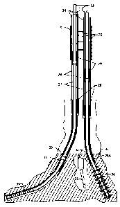
[00018] Figure 20 depicts a bottom plan view of the chamber junction of
Figure 18.
[00019] Figure 21 depicts an isometric view of the cross section shown in
Figure 19.
[00020] Figure 22 depicts a top plan view of an embodiment of a bore
selection tool
usable with the chamber junction of Figure 18.
[00021] Figure 23 depicts a cross-sectional view of the bore selection tool
of Figure 22 a
long line F-F.
3
CA 02744200 2011-05-19
[00022] Figure 24 depicts an isometric view of the cross sections of
Figures 19 and 23,
showing the bore selection tool disposed within the chamber junction.
[00023] Figure 25 depicts a top plan view of an alternate embodiment of a
double walled
chamber junction.
[00024] Figure 26 depicts a cross-sectional view of the chamber junction of
Figure 25
along line G-G.
[00025] Figure 27 depicts a bottom plan view of the chamber junction of
Figure 25.
[00026] Figure 28 depicts an isometric view of the cross section shown in
Figure 26.
[00027] Figure 29 depicts an isometric cross-sectional view of the chamber
junction of
Figure 25 engaged with an additional double walled chamber junction.
[00028] Figure 30 depicts a top plan view of an embodiment of a bore
selection tool
usable for insertion into the chamber junction of Figure 25.
[00029] Figure 31 depicts a cross-sectional view of the bore selection tool
of Figure 30.
[00030] Figure 32 depicts an isometric cross-sectional view of the chamber
junction of
Figure 25 engaged with the bore selection tool of Figure 30.
[00031] Figure 33 depicts a top plan view of another embodiment of a series
of chamber
junctions.
[00032] Figure 34 depicts a cross-sectional view of the chamber junctions
of Figure 33
along line I-I.
[00033] Figure 35 depicts an isometric view of the cross section of Figure
31, depicting a
bore selection tool.
[00034] Figure 36 depicts an isometric view of the cross section of Figure
34, depicting a
series of chamber junctions.
[00035] Figure 37 depicts an isometric view of the cross section of Figure
23, depicting a
bore selection tool.
4
CA 02744200 2011-05-19
[00036] Figure 38 depicts an isometric view of the cross sections of
Figures 31 and 34,
depicting the bore selection tool of Figure 31 disposed within the chamber
junction of Figure 34.
[00037] Figure 39 depicts an isometric view of the cross sections of
Figures 34 and 37,
depicting the bore selection tool of Figure 37 disposed within the chamber
junction of Figure 34.
[00038] Figure 40 depicts an isometric view of an embodiment of a bore
selection tool
usable for insertion into the chamber junction of Figure 41.
[00039] Figure 41 depicts an isometric view of an embodiment of a chamber
junction
secured to the upper end of conduits, such as those depicted in Figure 3.
[00040] Figure 42 depicts an isometric view an embodiment of a chamber
junction
usable for insertion into the chamber junction of Figure 41 to create a series
of
chamber junctions.
[00041] Figure 43 depicts an isometric view of an embodiment of a bore
selection tool
usable for insertion into the chamber junction of Figure 42.
[00042] Figure 44 depicts a diagrammatic elevation plan view illustrating
an
embodiment of a method for configuring additional orifices to respective
chambers in the chamber junctions of Figures 41 and 42.
[00043] Figure 45 depicts a partial diagrammatic view of the chamber
junction of Figure
44 along line A-A illustrating the shape of the interface between the chamber
and the additional orifices.
[00044] Figure 46 depicts a partial diagrammatic view of the chamber
junction of Figure
44 along line B-B illustrating the shape of the interface between the chamber
and the additional orifices.
[00045] Figure 47 depicts an elevation isometric view of an embodiment of a
bore
selection tool.
CA 02744200 2011-05-19
[00046] Figure 48 depicts an elevation isometric view of an embodiment of a
chamber
junction with an outer wall encircling conduits in communication with the
additional orificies
[00047] Figures 49-50 depict isometric plan views of an embodiment of a
chamber
junction usable with the bore selection tool of Figure 47.
[00048] Figure 51 depicts the bore selection tool of Figure 47 inserted
within the
chamber junction of Figure 48.
[00049] Figure 52 depicts an isometric view of an embodiment of a chamber
junction
having flexible connector arrangements to facilitate installation.
[00050] Figure 53 depicts an elevation view of an embodiment of a chamber
junction
having secured valves for controlling communication between the chamber and
associated conduits.
[00051] Figures 54-57 depict diagrammatic views of the installation of
conduits secured
to the lower end of the chamber junction of Figure 53, with Figures 55 and 57
depicting top plan views of Figures 54 and 56, respectively.
[00052] Figure 58 depicts a top plan view of an embodiment of a double
walled chamber
junction with multiple conduit orficies contained within an outermost orifice.
[00053] Figure 59 depicts a cross-sectional view of the chamber junction of
Figure 58
along line J-J.
[00054] Figure 60 depicts a top plan view of a bore selection tool usable
with the
chamber junction of Figure 58.
[00055] Figure 61 depicts a cross-sectional view of the bore selection tool
of Figure 60
along line K-K.
[00056] Figure 62 depicts an isometric cross-sectional view of the bore
selection tool of
Figure 60 inserted within the chamber junction of Figure 58.
6
CA 02744200 2011-05-19
[00057] Figure 63 depicts a top plan view of an embodiment of a double
walled chamber
junction with a conduit having a plurality of additional orifices and a
condiuit
having a single additional orifice within an outermost orifice.
[00058] Figure 64 depicts an isometric view of a bore selection tool usable
with the
chamber junction of Figure 63.
[00059] Figure 65 depicts a sectional view of the chamber junction of
Figure 63 along
line L-L.
[00060] Figure 66 depicts the sectional view of the chamber junction of
Figure 65 with
the bore selection tool of Figure 64 inserted therein.
[00061] Figure 67 depicts an isometric view of an embodiment of a chamber
junction
having secured valves for controlling communication between the chamber and
conduits, with an installation apparatus for insertion into well bores or
other
chamber junctions.
[00062] Figure 68 depicts an alternate embodiment of the chamber junction
of Figure 67
having an alternative configuration replacing the upper end along line M-M.
[00063] Figure 69 depicts a top plan view of the chamber junction of Figure
68.
[00064] Figure 70 depicts a top plan view of an alternate embodiment of a
chamber
junction having a wear protection apparatus.
[00065] Figure 71 depicts an isometric elevation view of a portion of the
chamber
junction of Figure 67 with the addition of cross-over communication between
conduits to create a by-pass manifold.
[00066] Figure 72 depicts an elevation view of a bore selection tool usable
with the
chamber junction of Figure 70.
[00067] Figure 73 depicts a partial plan view of the bore selector of
Figure 72.
[00068] Figure 74 depicts an elevation view of the partial bore selection
tool of Figure
73.
7
CA 02744200 2011-05-19
[00069] Figure 75 depicts a top plan view of an embodiment of a multi-part
chamber
junction prior to performing the method of installation depicted in Figure 12
through Figure 15.
[00070] Figures 76 depicts a partial isometric view along line N-N,
depicting portions of
the smaller chamber junction of Figure 75 contained within the larger chamber
junction.
[00071] Figure 77 depicts a partial isometric view of portions of the
larger chamber
junction of Figure 76.
[00072] Figure 78 depicts a partial view of the isometric sectional view of
the larger
chamber junction of Figure 77, within line 0.
[00073] Figure 79 depicts an isometric sectional view of a portion of the
smaller
chamber junction of Figure 76, with the chamber separated along line C between
the conduits of the additional orifices
[00074] Figure 80 depicts an isometric sectional view of the multi-part
chamber junction
created by sequentially inserting and securing the smaller chamber parts of
Figure 79 into the larger chamber junction of Figure 78.
[00075] Figures 81 and 82 depict an embodiment of a multi-part chamber
junction, with
Figure 81 depicting the individual parts of the chamber junction and Figure 82
depicting the parts of Figure 81 assembled.
[00076] Figure 83 depicts a top plan view of a securing tool usable to
secure a multi-part
chamber junction.
[00077] Figure 84 depicts a cross-sectional view of the securing tool of
Figure 83 along
line P-P.
[00078] Figures 85 and 86 depict magnified views of portions of the
securing tool of
Figure 84 within lines Q and R, respectively.
[00079] Figure 87 depicts an isometric view of an embodiment of a multi-
part chamber
junction including securing apparatuses.
8
CA 02744200 2011-05-19
[00080] Figures 88-91 depict magnified views of portions of the chamber
junction of
Figure 87, with Figures 88, 90, and 91 depicting the portions of Figure 87
within
lines S, T, and U, respectively, and Figure 89 depicting an embodiment of a
securing apparatus usable with the chamber junction of Figure 87.
[00081] Figure 92 depicts a top plan view of an embodiment of a chamber
junction.
[00082] Figure 93 depicts a cross-sectional view of the chamber junction of
Figure 92
along line V-V.
[00083] Figures 94 and 95 depict magnified views of portions of the chamber
junction of
Figure 93, within lines W and X, respectively.
[00084] Figures 96 and 97 depict an embodiment of a multi-part and multi-
walled
chamber junction, with Figure 96 depicting the individual parts of the chamber
junction and Figure 97 depicting the parts of Figure 96 assembled.
[00085] Embodiments of the present invention are described below with
reference to the
listed Figures.
DETAILED DESCRIPTION OF THE EMBODIMENTS
[00086] Before explaining selected embodiments of the present invention in
detail, it is
to be understood that the present invention is not limited to the particular
embodiments described herein and that the present invention can be practiced
or
carried out in various ways.
[00087] The present invention relates, generally, to systems and methods
usable to
produce, inject, and/or perform operations on a plurality of wells, including
multiple, laterally spaced wells, through a single main bore. To provide
access
to each of a desired selection of wells, one or more chamber junctions are
provided in fluid communication with one or more conduits within the single
main bore. The chamber junction is a construction having a chamber and
plurality of orifices that intersect the chamber. A first of the orifices is
used to
communicate with the surface through subterranean strata, via one or more
conduits within the main bore, while one or more additional orifices within
the
9
CA 02744200 2011-05-19
chamber junction are usable to communicate with any number of well bores
through associated conduits. Thus, a chamber junction can have any shape or
arrangement of orifices necessary to engage a desired configuration of
conduits.
[00088] Any number and any arrangement of chamber junctions and/or
communicating
conduits can be inserted or urged through the single main bore and assembled,
in series or in parallel, to accommodate any configuration of wells. Chamber
junctions and conduits can also be assembled concentrically or eccentrically
about one another, which both defines annuli usable to flow substances into or
from selected wells, and provides multiple barriers between the surrounding
environment and the interior of the chambers and conduits. A composite
structure is thereby formed, which can include any number of communicating or
separated conduits and chambers, with or without annuli, each conduit and/or
annulus usable to communicate substances into or from a selected well.
[00089] Each of the wells can be individually or simultaneously accessed,
produced,
injected, and/or otherwise operated upon by inserting a bore selection tool
into
the chamber junction. The bore selection tool can include an exterior wall, an
upper opening that is aligned with the first orifice when inserted, and one or
more lower openings, each aligned with an additional orifice of the chamber
junction to enable communication with the associated well bores. Use of a bore
selection tool enables selective isolation and/or communication with
individual
wells or groups of wells, for performing various operations, including
drilling,
completion, intervention operations, and other similar undertakings. Required
tools and equipment, drilling bottom hole assemblies, coiled tubing, wire line
bottom hole assemblies, and similar items for performing an operation on a
selected well bore can be lowered through the conduit, into the upper opening
of
the bore selection tool disposed within the chamber junction, then guided by
the
bore selection tool through a lower opening in the bore selection tool to
enter the
selected well bore. In one or more embodiments of the invention, the
arrangement of the orifices within each chamber junction, can cause certain
orifices to have an incomplete circumference. In such an embodiment, the bore
selection tool can include an extension member sized and shaped for passage
into one of the orifices, such that the extension member completes the
CA 02744200 2016-05-20
circumference of the selected orifice when the bore selection tool is properly
inserted and oriented, thereby enabling communication with the respective well
through the orifice while isolating other orifices.
[00090] By providing selective access to a plurality of well bores through
a single main
composite bore, the present systems and methods provide greater efficiency and
reduced expense over existing methods by reducing above-ground equipment
requirements and reducing or eliminating the need to move, erect, and
disassemble drilling rigs and similar equipment.
[00091] Conventional methods for reducing the number of conduits and the
quantity of
above-ground equipment used to produce or otherwise operate on a well are
generally limited, the most common of such methods being the drilling of
multilateral wells, which include multiple dependent bores drilled in a
generally
lateral direction from a central, main bore. Various embodiments of
multilateral
well technology are described in U.S. Patent 5,564,503. Figure 1 depicts an
exemplary embodiment of a multilateral configuration, which includes an
offshore
drilling rig (1) having multiple lateral well bores branching from a main well
bore.
Various types of lateral well bores are depicted, including unsealed junctions
(2),
an unsealed series of fish-bone multilateral junctions (3), and mechanically
sealed
junctions (4), each branching from a single main bore.
[00092] To avoid the risk of collapse, lateral completion is typically only
usable within
competent rock formations, and the ability to access or re-enter the lateral
well
bore is limited, as is the ability to isolate production zones within the well
bore.
Further, lateral well bores are limited in their use and placement, being
unsuitable
for use within surface and near-surface regions of strata due to their
generally
open-hole construction.
[00093] The alternative to multilateral wells and similar methods includes
the unrestricted
spacing of single well bores within a region. Figure 2 depicts numerous
onshore
surface production trees (5) spaced from one another to produce a subterranean
reservoir through multiple well bores, each surface
11
CA 02744200 2011-05-19
production tree (5) usable to access a single well bore. Use of this
unrestricted
method is suitable only when the quantity of space occupied by production
equipment is not an economic or environmental concern, and when the
complexity of the production operations is low.
[00094] The present systems and methods overcome the limitations of the
conventional
approaches described above, and are usable to operate on any type or
combination of wells, individually or simultaneously, including but not
limited
to producing hydrocarbons or geothermal energy, injecting water or lift gas to
facilitate production, disposing of waste water or other waste substances into
a
waste well, injecting gas for pressure maintenance within a well or gas
storage
within a storage well, or combinations thereof. Further, the present systems
and
methods provide the ability to access each well, simultaneously or
individually,
for any operations, including batch completion operations, batch drilling
operations, production, injection, waste disposal, or other similar
operations,
while preventing the migration and/or contamination of fluids or other
materials
between well bores and/or the environment.
[00095] Additionally, any number of valves, manifolds, other similar
equipment, or
combinations thereof, can be disposed in communication with the chamber
junction in a subterranean environment within the composite main bore. A
single valve tree or similar apparatus can then be placed in communication
with
the upper end of the main bore, the valve tree being operable for
communicating
with any of the wells. Conventional systems for combining multiple well bore
conduits within a single tree are generally limited to above ground use,
consuming surface space that can be limited and/or costly in certain
applications. Additionally, unlike above-ground conventional systems,
embodiments of the present system are usable in both above ground applications
and subsea applications to reduce the quantity of costly manifolds and
facilities
required.
[00096] The present invention also relates to a method for providing
communication
with a plurality of wells through formation of chamber junctions. A plurality
of
conduits, which can include concentric conduits, can be provided and arranged,
12
CA 02744200 2011-05-19
such that the upper end of each conduit is generally proximate to that of each
other conduit. One or more main conduits, having an open upper end and a
closed lower end, can then be provided, such that the upper ends of the
plurality
of conduits are enclosed by a main conduit. Material from the conduits, which
can include portions of the main conduit, can be removed to form additional
orifices for communication with one or more wells. Similarly, material from
the
main conduit, which can include portions of the conduits used to form the
additional orifices, can be removed to define a chamber, with each of the
conduits intersecting the chamber at one of the additional orifices. A bore
selection tool with an upper orifice corresponding to the chamber upper end
and
one or more lower orifices corresponding to one or more of the additional
orifices can be inserted into the chamber for providing access to one or more
well bores through selected additional orifices while isolating other well
bores.
[00097] The present systems and methods thereby provide the ability to
produce, inject,
and/or perform other operations on any number of wells within a region,
through
one or more conduits within a single bore, while enabling selective isolation
and
selective access to any individual well or combinations of wells. A minimum of
surface equipment is required to access and control operations for each of the
wells placed in communication with the chamber junction, a single valve tree
being sufficient to communicate with each well through one or more conduits
within the single bore.
[00098] Referring now to Figure 2A, an exemplary embodiment of the present
system is
depicted in which an environmental Riser (125) used for taking returns to the
surface during subsea drilling operations is connected with and used to run a
wellhead housing (124), which in turn is connected to a permanent guide base
(122) with subsea posts (123) to facilitate guidelines to surface.
[00099] In the depicted embodiment, a bore hole capable of accepting a
conductor casing
chamber (43) or chamber junction can be urged axially downwards with the
conductor casing chamber (43) attached to the wellhead housing (124),
permanent guide base (122), and subsea posts (123), such that multiple
components can be run as a single unit and cemented in place (121).
13
CA 02744200 2011-05-19
[000100] It should be noted that Figure 2A depicts a single exemplary
embodiment and
that other embodiments of the present system can include the use of a wellhead
housing (124) and conductor casing chamber (43).
[000101] The conductor casing chamber (43) attached to the wellhead housing
(124)
includes a guide template (113) to accept intermediate casing (115) with
polished bore receptacles (112) at the top of each intermediate casing (115).
[000102] To facilitate formation of an outer differential pressure barrier for
the inclusion
of gas lift or other stimulation measures, the space between the subterranean
formation, conductor casing chamber (43), guide template (113), and
intermediate casing (115) can be grouted (114) using a stab-in connector (not
shown in Figure 2A). In this manner, a differential pressure containment
envelope is created around any equipment installed within, which provides a
final barrier against escape of fluids, gas, or vapors from the inner most
tubing.
[000103] Referring now to Figure 2B, an exemplary embodiment of the present
system is
depicted in which a subsea wellhead connector (116) and environmental riser
for
taking fluids to the surface, are attached to a subsea wellhead (117) with a
differential pressure containment chamber (43) or chamber junction attached
below the subsea wellhead (117). Other embodiments of the present system can
also include use of a wellhead and chamber assembly, similar to the depicted
embodiment in an above sea level offshore or an onshore environment.
[000104] The differential pressure containment chamber (43), with connectors
and PBR
mandrels attached below using inclined connectors (120), is run axially
downward and plugged into the polished bore receptacles (112), attached to the
intermediate casing (115) to form a differential pressure control barrier for
preventing the escape of fluids, gas, or vapors, from the production or
injection
tubing, wherein the annulus pressure between the chamber junction (41 of
Figure 2A) and chamber junction (41 of Figure 2B) may be made positive or
negative. In above sea level applications the annulus pressure may be made
positive, negative or generally equal to atmospheric pressure. Inclusion of a
negatively pressured annulus providing thermal insulation has benefits in high
14
CA 02744200 2011-05-19
temperature wells, artic wells through permafrost, and other environmentally
sensitive environments where the differential pressure containment chamber
(43) or chamber junction may be used to reduce both thermal radiation and the
number of wells radiating subterranean heat or cold from gas expansion in gas
storage wells.
[000105] Referring now to Figure 3, a cross-sectional view of multiple,
laterally separated
well bores is shown, engaged with an embodiment of the present system, such as
those depicted in Figures 41, 42, and 67. A composite main bore (6) is
depicted,
secured to an intermediate casing or conduit (29) below, which is shown in
communication with three laterally separated well bores within a reservoir
(33).
Tubing conduits (23) communicate between the composite main bore (6) and
each laterally separated well bore through intermediate conduits (27).
[000106] The first well bore is shown including sand screens (34) for near
horizontal sand
screen completion. The sand screens (34) and tubing conduit are placed in an
unsupported or gravel-packed subterranean bore and tied back with tubing using
a packer (31) to a liner or casing. An upper completion tubing conduit (27)
with
a second packer (30) at its bottom communicates with the well bore and is tied
back to a polished bore receptacle and mandrel seal stack (26), which is
secured
to the tubing conduit (23) extending through the composite main bore (6).
[000107] The second well bore illustrates an open hole completion operation
drilled
underbalanced with coiled tubing (35), which is generally undertaken to
minimize skin damage that occurs when performing through tubing conduit
drilling methods.
[000108] The third well bore illustrates a cement and perforated liner
completion, in
which cement (32) disposed about a conduit or liner (28A) is provided with
perforations (36). A liner hanger and top packer (28) are used to secure the
conduit or liner (28A) to the bottom of the intermediate casing or conduit
(29).
[000109] In situations where a higher pressure bearing capacity is necessary,
additional
conduits (24) can be secured via securing devices (25) to the intermediate
casing
or conduit (29).
CA 02744200 2011-05-19
[000110] Referring now to Figures 4 through 7, a composite main bore (6) is
shown
communicating with multiple laterally separated well bores that would normally
be inaccessible from a single surface location using conventional multilateral
branched methods. Each of the depicted well bores is usable for differing
types
of production and/or injection operations.
[000111] Figure 4 depicts the lower end of the composite main bore (6) engaged
with two
production well bores (7) and a third well bore (8) used for injecting water
into a
subterranean water table (10) to maintain pressure within the reservoir (9)
using
a water flood method.
[000112] Figure 5 depicts the lower end of the composite main bore (6) engaged
with a
first well bore (11) producing from a first geologic fault block, a second
well
bore (12) producing from a second geologic fault block, and a third well bore
(13) producing from a third geologic fault block. Use of three laterally
separated, low inclination well bores, as depicted, to produce from different
fault blocks provides benefits over conventional use of long horizontal wells.
Chokes and/or orifices can be provided to the composite bore design to
regulate
pressure differences and reduce back-out of production when reservoirs having
differing pressures exist, through an intelligent completion method.
[000113] Figure 6 depicts the lower end of the composite main bore (6) engaged
with a
first well bore (14) producing from an intermediate depth (18), a second well
bore (15) producing from a shallow depth (17), and a third well bore (16)
producing from a lower depth (19). Each of the well bores (14, 15, 16) can
produce until the subterranean water level rises past the corresponding depth
(17, 18, 19), at which time production from the respective well bore can then
be
ceased. The ability to prevent the flow of water through the well bores can be
accomplished by the addition of valves to conduits of the composite main bore
(6) below a chamber junction within the composite main bore (6), enabling use
of an intelligent completion method with zonal isolation capabilities.
Placement
of conventional plugs and prongs for zonal isolation is also possible during
well
intervention using a bore selection tool, as described previously. The
addition
of the described flow control capabilities to the depicted composite well
16
CA 02744200 2011-05-19
structure reduces the quantity of water handling equipment with shut-off
protection features necessary during production operations in the presence of
water, providing a significant reduction in the time and expense related to
such
an operation.
[000114] Figure 7 depicts the lower end of the composite main bore (6) engaged
with a
first well bore (21) to a geologic feature, a laterally separated well bore
(22) to a
region of the geologic feature that could not be effectively drained using the
first
well bore (21), and an additional well bore (20) that communicates with a
separate subterranean feature for storage or waste disposal.
[000115] Referring now to Figures 8 through 13, embodiments of stages of a
method
usable to construct a chamber junction for communication between the
composite main bore and multiple well bores are depicted, in successive stages
of construction.
[000116] Figure 8 depicts an elevation isometric view, and Figure 9 depicts a
top plan
view, of a partial chamber junction (37), having overlapping projections of
additional orifices converging, or proximate, to the diameter of a first
orifice
(38), corresponding to cut plane A-A, usable to communicate with a conduit
within the single main bore, and additional orifice conduits (39) with lower
ends
corresponding to cut plane B-B, usable to communicate with differing well
bores. The centerlines of each additional orifice conduit (39) are separated
at
the base of the partial chamber junction (37), but converge at or proximate to
the
first orifice (38), enabling alignment and access to each additional orifice
(39)
when a bore selection tool is placed within the first orifice.
[000117] Figure 10 depicts an elevation isometric view, and Figure 11 a plan
view, of an
assembled chamber junction (40), having a conduit disposed about the partial
chamber junction (37, depicted in Figure 8), defining a chamber (41) above
each
of the additional orifice conduits (39). The conduit is shown having an open
cavity at its upper end (referred to as the first orifice) walls penetrated
only by
the inner diameter of the additional orifice conduits (39), and a closed
bottom
(42) to define the chamber (41).
17
CA 02744200 2011-05-19
[000118] Figure 12 depicts an elevation isometric view, and Figure 13 a plan
view, of a
completed chamber junction (43), with a conduit, having a first orifice at its
upper end and all material removed from the internal diameter of the
additional
orifice conduits (39), creating usable additional orifices extending from the
chamber (41). The additional orifice conduits (39) are shown meeting and
commingling at a securing point (44) within the chamber (41).
[000119] Extending the length of the additional orifice conduits (39) enables
the central
axis of the additional orifice conduits (39) to have a low angle of divergence
from the central axis of the chamber (41), which aids passage of various tools
and apparatuses through a bore selection tool inserted into the chamber (41)
of
the chamber junction (43) and into additional orifice conduits (39). In
various
embodiments of the invention, to maintain small angular deflections from
vertical within the chamber junction (43), long chamber junctions can be
utilized. Long chamber junctions can be split into parts sized for insertion
into
a subterranean bore.
[000120] As shown in Figures 8 and 10, cut planes A-A and B-B demonstrate
potential
split planes for a chamber junction perpendicular to its central axis for
facilitating unitization and insertion of the chamber junction into
subterranean
strata. Cut plane A-A illustrates the upper end of overlapping projections of
additional orifices along their central axis, converging or proximate to the
diameter of the first orifice (38), and is axially above cut plane B-B, which
illustrates the lower end of the additional orifice projections. It should be
noted
that the position of cut planes A-A and B-B are exemplary, and that the any
number of cut planes can be positioned anywhere along the central axis of the
converging projections. The depicted chamber junction (43) is thereby defined
by the additional orifice conduits (39) and the angular orientation between
the
cut planes A-A and B-B, wherein the conduits are secured to a chamber (41)
having a first orifice at its upper end, a closed lower end (42), and an open
cavity capable of accepting a bore selection tool, with chamber walls having
communicating passageways to the internal diameters of the additional orifice
conduits (39).
18
CA 02744200 2011-05-19
[000121] Figure 13 depicts cut plane C-C-C, which demonstrates split planes
for a
chamber junction through its central axis, whereby a smaller unitized or split
chamber junction, such as that shown in Figures 12 and 13 can be unitized,
inserted into and secured to a larger partial chamber junction, such as that
depicted in Figures 14 and 15, to facilitate downhole construction of a
unitized
chamber junction when the diameter of the main bore limits the size of
apparatuses that can be inserted therein.
[000122] Referring now to Figures 14 and 15, Figure 14 depicts an elevated
isometric
view, and Figure 15 a plan view, of a partial chamber junction (45), with a
chamber having a closed lower end (42), with the additional orifice conduits
(39) having portions removed external to a maximum outside diameter, joined
with the chamber at securing points (44), to accommodate downhole
construction of a chamber junction through a bore having a limited maximum
diameter. Additional portions of a chamber junction, such as those formed by
cutting the chamber junction (43) of Figure 13 along cut plane C-C-C can be
inserted into the partial chamber junction (45) to form a complete chamber
junction.
[000123] Referring now to Figures 16 and 17, an elevation isometric view and a
plan
view, respectively, of an embodiment of a bore selection tool usable within
the
chamber junction (43) of Figure 12 is shown. The bore selection tool (47) is
shown having an internal bore (49) extending therethrough, terminating at a
lower orifice and/or selection bore (50), which aligns with an additional
orifice
of the chamber junction when the bore selection tool (47) is inserted into the
chamber therein. Similarly, the upper opening of the internal bore (49)
coincides approximately with the first orifice of the chamber junction when
the
bore selection tool (47) is inserted. The lower end of the bore selection tool
(47)
can be unitized into an extension member (48) using cut plane D-D, which
coincides with cut plane A-A and is relative to the internal bore (49), the
extension member (48) being sized and configured to complete the
circumference of the additional orifice conduit (39) aligned with the internal
bore (49), within the chamber of the chamber junction. In instances where an
extension member (48) formed at the lower end of a bore selection tool is
19
CA 02744200 2011-05-19
inserted into a chamber, the upper end of the bore selection tool can protrude
outside of the chamber, extending into the conduit engaged with the upper end
of the chamber.
[000124] Referring now to Figures 18-21, a junction of wells (51) is depicted,
at which a
plurality of wells can selectively be permitted to commingle. The junction of
wells (51) is defined by a multi-part or double walled chamber junction, which
is depicted including two individual chamber junctions (43) concentrically
disposed about one another, each defining a chamber (41) within. Additional
orifice conduits (39) extend therefrom, which are shown as double-walled
concentric conduits. The resulting double-walled structure, defining an
annular
space, provides two barrier walls and isolation between the innermost cavities
of
the conduits and the subterranean environment in which they are contained.
[000125] Figure 19 depicts a cross-sectional view of the junction of wells
(51) shown in
Figure 18, along line E-E, which more clearly depicts a smaller chamber
junction disposed within a larger chamber junction. The chambers (41) and
additional orifice conduits (39) of the chamber junctions (43) are shown
secured
together at a securing point (44), proximate to the closed chamber bottom (42)
and walls of the chamber junctions (43), such that the bottom of each chamber
junction is generally parallel. The centerline of the chamber (41) and that of
each additional orifice conduit (39) are shown crossing at a junction point
(52),
where the communicating passageways from each additional orifice conduit (39)
commingle within the chamber (41) or conduit engaged at the upper end of the
chamber (41), unless isolated using a bore selection tool or other isolation
devices. Figure 20 depicts a bottom plan view of the junction of wells (51),
which more clearly depicts the concentric additional orifice conduits (39),
secured to the chamber (41) at the securing points (44) proximate to the
bottom
(42) and walls of the chamber (41).
[000126] Referring now to Figures 22 and 23, an embodiment of a bore selection
tool
usable with the chamber junction of Figures 18-21 is shown. The bore selection
tool (47) is depicted as a tubular member sized for insertion within the upper
orifice of the chamber (41) of the innermost chamber junction, the bore
selection
CA 02744200 2011-05-19
tool (47) having an internal bore (49), which extends through the body of the
bore selection tool (47) at an angle, to terminate at a lower orifice and/or
selection bore (50). The internal bore (49) can be concentric, eccentric,
tapered,
angled, straight, or have any other desired shape or angle, depending on the
orientation of the additional orifice conduit to be isolated in relation to
the upper
orifice of the chamber junction. Additional orientation and/or guidance
apparatuses can also be engaged with the upper end of a bore selection tool
and/or an extension member, as described previously, with the upper end of the
extension defined by cut plain D-D, such that an additional apparatus resides
within the conduit engaged to the upper end of the chamber of a chamber
junction.
[000127] Figure 24 depicts an isometric cross-sectional view of the chamber
junction of
Figures 18-21 having the bore selection tool of Figures 22 and 23 inserted
therein. The upper portion of the internal bore (49) is shown in alignment
with
the upper orifice of the chamber junction, within the chamber (41), while the
selection bore (50) of the bore selection tool (47) is oriented to align with
one of
the additional orifice conduits (39) of the chamber junction. It should be
noted
that when the depicted bore selection tool (47) enables access to an
individual
selected additional orifice conduit (39), each other additional orifice
conduit is
isolated by the exterior surface of the bore selection tool (47).
[000128] Referring now to Figures 25 through 28, an alternate embodiment of a
multi-part
chamber junction is depicted, having two concentric chamber junctions (43),
with two concentric additional orifice conduits (39), the first extending
generally
downward opposite the upper first orifice, and the second extending at an
angle
from the central axis of the chamber (41), the depicted structure defining a
junction of wells (51). As described previously, the concentric chamber
junctions (43) are secured at securing point (44) proximate to the bottom (42)
and walls of each chamber (41) of each chamber junction (43). The centerlines
of each additional orifice conduit (39) and the chamber (41) coincide at a
junction point (52).
[000129] Referring now to Figure 29, the chamber junction of Figures 25-28 is
depicted,
21
CA 02744200 2011-05-19
in a vertical engagement with a second chamber junction of similar
construction.
The second chamber junction is shown engaged with the lowermost additional
orifice conduit of the first chamber junction, thereby providing a composite
structure having one additional orifice conduit (39) vertically displaced from
another, and a lower additional orifice conduit (39) extending in a generally
downward direction, defining a junction of wells (51). Any number of chamber
junctions having any configuration of additional orifices can be stacked or
otherwise arranged in series and/or in parallel, enabling provision of
additional
orifice conduits oriented to engage well bores of varying configurations,
rotationally or axially displaced from one another by any distance or angle.
[000130] Referring now to Figures 30 and 31, an embodiment of a bore selection
tool is
shown, the bore selection tool (47) having a generally tubular shape with an
angled internal bore (49) at its upper end that terminates at a selection bore
(50)
along a side of the bore selection tool (47).
[000131] Figure 32 depicts the bore selection tool (47) of Figures 30 and 31
engaged
within the chamber junction (43) of Figures 25-28. As shown, when inserted
within the first orifice at the upper end of the chamber junction, the
selection
bore (50) of the bore selection tool (47) aligns with an additional orifice of
the
chamber junction, enabling operations to be performed on the well that
corresponds to the aligned additional orifice by passing tools, coiled tubing,
and/or other similar objects through the internal bore (49) of the bore
selection
tool, while one or more other wells are isolated, after which the bore
selection
tool (47) can be removed to restore communication between all additional
orifices and the first orifice.
[000132] Referring now to Figures 33, 34, and 36, a junction of wells (51) is
depicted,
defined by two stacked chamber junctions. The upper chamber junction is
shown having two additional orifice conduits (39) a first extending generally
downward opposite the upper first orifice, and a second extending outward at
an
angle from the side of the chamber junction, both additional orifice conduits
(39) intersecting a chamber (41) at a securing point (44). The lower of the
additional orifice conduits (39) is shown in communication with the second
22
CA 02744200 2011-05-19
double walled chamber junction secured below. The lower chamber junction is
shown having two additional orifice conduits (39), each extending outward at
an
angle proximate to the bottom of the lower chamber junction, similarly
intersecting the chamber (41) at a securing point (44).
[000133] Figure 35 depicts an embodiment of a bore selection tool (47), having
an
internal bore (49) that is angled through the body of the bore selection tool
(47)
such that the selection bore (50) at which the internal bore (49) terminates
will
be aligned with an additional orifice of the upper chamber junction of Figures
33, 34, and 36 when the bore selection tool (47) is inserted therein.
[000134] Figure 38 depicts the junction of wells (51), having the bore
selection tool of
Figure 35 inserted within the upper double walled chamber junction of Figures
33, 34, and 36, showing alignment between the selection bore (50) bore of the
bore selection tool and the additional orifice of the upper double walled
chamber
junction.
[000135] Figure 37 depicts an alternate embodiment of a bore selection tool
(47), having
an internal bore (49) that is angled through the body of the bore selection
tool
(47) such that the selection bore (50) at which the internal bore (49)
terminates
will be aligned with an additional orifice of the lower double walled chamber
junction of Figures 33, 34, and 36, when the bore selection tool (47) is
inserted
therein.
[000136] Figure 39 depicts the junction of wells (51), having the bore
selection tool of
Figure 37 inserted within the lower chamber junction of Figures 33, 34, and
36,
showing alignment between the selection bore (50) bore of the bore selection
tool and one of the additional orifices of the lower chamber junction. In an
embodiment of the invention, the lower end of the bore selection tool can
include an extension member, as described previously, enabling additional
apparatuses for guidance and/or orientation to be placed within the conduits
and/or chamber junctions, such as through engagement to the upper end of the
chamber of the innermost chamber junction.
[000137] As demonstrated in Figures 33-39, and in the preceding depicted and
described
23
CA 02744200 2011-05-19
embodiments, any combination and configuration of chamber junctions having
additional orifices, and other communicating conduits, can be constructed
concentrically, in series, and/or in parallel, to accommodate any desired well
bore orientation, and any configuration of additional orifice conduits can be
made accessible and/or isolated using one or more corresponding bore selection
tools.
[000138] Embodiments of the present system can be installed by urging a
subterranean
bore into subterranean strata, then placing the lower end of a chamber
junction
at the lower end of the subterranean bore. A conduit is placed within the
bore,
its lower end connected to the upper end of the chamber junction.
Sequentially,
a series of additional subterranean bores can then be urged through one or
more
additional orifice conduits of the chamber junction, such as by performing
drilling operations through the chamber junction and associated conduits. The
upper ends of the conduits that extend within the additional subterranean
bores
can be secured to the lower ends of the additional orifice conduits. To
sequentially access each additional orifice conduit when urging or interacting
with additional subterranean bores extending to similar depths through similar
geologic conditions, a bore selection tool, as described previously, can be
inserted into the chamber junction to isolate one or more of the additional
orifice
conduits from one or more other additional orifice conduits, while
facilitating
access through the desired additional orifice for interacting with, urging
axially
downward and/or placing conduits or other apparatuses within the bores of the
accessed well.
[000139] The drilling, completion, or intervention of a series of subterranean
bores in this
batch or sequential manner provides the benefit of accelerating application of
knowledge gained before it becomes lost or degraded through conventional
record keeping methods or replacement of personnel, as each of the series of
bores will pass through the same relative geologic conditions of depth,
formation, pressure, and temperature within a relatively condensed period of
time compared to conventional methods, allowing each subsequent bore to be
drilled, completed, or otherwise interacted with more efficiently.
24
CA 02744200 2011-05-19
[000140] Referring now to Figure 41, an isometric view of an embodiment of a
chamber
junction (43) for placement at the lower end of a subterranean bore is
depicted,
having a chamber (41), with three additional orifice conduits (39) shown
disposed proximate to the chamber bottom (42). Each additional orifice conduit
(39) is depicted having a polished bore receptacle (61) or similar connector
for
connection with other apparatuses, such as mandrel seal stacks at the lower
end
of an additional chamber junction, such as that depicted in Figure 42. A key
or
slot, (58) or similar internal protrusion or receptacle is shown, usable to
engage
with bore selection tools and/or other chamber junctions having a
complementary protrusion or receptacle, to cause alignment and orientation of
the objects engaged therewith. The chamber junction (43) is also shown having
a circulating port (59) or bypass conduit, usable to flow fluid between the
chamber (41) and the adjacent annulus, for removing cuttings, placing cement,
and flowing fluids for similar operations. Once the chamber junction is placed
and secured at the lower end of a subterranean bore, batch operations through
the additional orifice conduits (39) can be performed, and the lower end of
the
chamber junction (43) can be engaged with the upper end of conduits
communicating with wells, such as those depicted in Figure 3, while the upper
end of the chamber junction can be engaged with an upper conduit that
communicates with the composite main bore.
[000141] Figure 40 depicts a bore selection tool (47) usable for insertion
into the chamber
junction of Figure 41. The bore selection tool (47) is shown having an index
key or slot (55), which can engage with the key or slot of the chamber
junction
to orient the bore selection tool (47) within the chamber. The bore selection
tool
(47) is shown having an eccentric bore (56) with a lower end (57) that will
align
with one of the additional orifice conduits of the chamber junction of Figure
41
when the bore selection tool (47) is inserted and oriented therein. The bore
selection tool (47) is also shown having a cavity (54) and a groove (53)
proximate to its upper end, for accommodating latching, locking, and/or
securing with a tool usable to insert and retrieve the bore selection tool
(47)
from the chamber junction.
[000142] Figure 42 depicts a smaller chamber junction (43), sized for
insertion into the
CA 02744200 2011-05-19
chamber junction of Figure 41 to form a multi-part, double-walled structure.
The depicted chamber junction (43) of Figure 42 includes a chamber (41) with
additional orifice conduits (39) extending a selected length (64) from the
chamber bottom (42) to engage a lower plate (67). It should be noted that due
to
the position of the cut plane A-A, described in Figure 8 and Figure 10,
applied
to the depicted chamber junction (43), each of the additional orifice conduits
(39) overlaps at their upper ends, such that each additional orifice conduit
(39)
has an incomplete circumference or cloverleaf shape at its upper end, such
that
an appropriately sized and shaped bore selection tool is usable to complete
the
circumference of a selected additional orifice conduit when isolating and
accessing the additional orifice conduit.
[000143] Figure 44 depicts an elevation diagrammatic view of a chamber
junction (43).
Figure 45 depicts a cut view of the chamber junction of Figure 44 along line A-
A, depicting the cloverleaf shape (63) of the overlapping additional orifices
having incomplete circumferences at their upper ends. Figure 46 depicts a cut
view of the chamber junction of Figure 44 along line B-B, depicting the
separation between the circumferences at the lower end of the additional
orifice
conduits (60). The selected length (64) of the additional orifice conduits can
be
represented by the distance between cut plane A-A and cut plane B-B.
[000144] Returning to Figure 42, mandrel seal stacks (66) are shown engaged
with the
lower end of each of the additional orifice conduits (39). When the chamber
junction (43) of Figure 42 is engaged with the chamber junction of Figure 41,
the mandrel seal stacks (66) can be secured within the polished bore
receptacles
(61, depicted in Figure 41), while the lower plate (67) can abut or be
positioned
proximate to the bottom of the chamber of the larger chamber junction. The
lower plate (67) is shown having a slot or key (65) formed therein, for
engagement with a corresponding slot or key within the larger chamber, causing
orientation of the smaller chamber junction (43) such that the additional
orifice
conduits (39) of each chamber junction are aligned.
[000145] Figure 43 depicts a bore selection tool (47) sized for insertion into
the smaller
chamber junction of Figure 42 having an extension member (48) at its lower
26
CA 02744200 2011-05-19
end. After the smaller chamber junction has been inserted within the larger
chamber junction, the depicted bore selection tool (47) is usable to isolate a
selected additional orifice conduit, for enabling communication with a
selected
well bore, by completing the incomplete circumference of the selected
additional orifice conduit. The bore selection tool (47) is depicted having a
groove (53) and a cavity (54) at its upper end, usable for securing and
manipulation of the bore selection tool (47) by an insertion and removal tool.
[000146] The bore selection tool (47) is shown having an eccentric bore (56)
with a lower
end (57) in alignment with the extension member (48), which is shown having a
partial internal bore (68) sized to complete the circumference of a selected
additional orifice conduit of the smaller chamber junction when inserted
therein.
An index key or slot (55) is shown, the key or slot (55) being configured to
engage with a complementary key or slot within the chamber junction, thereby
orienting the bore selection tool (47) to align the eccentric bore (56) with
an
additional orifice conduit.
[000147] When the bore selection tool (47) is inserted into the overlapping,
cloverleaf-
shaped securing point profile of the additional orifices of the chamber
junction
of Figure 42, the partial internal bore (68) of the extension member (48)
completes the circumference of the overlapping portion of the aligned
additional
orifice conduit, thereby providing the aligned additional orifice conduit with
a
full circumference to enable isolation from other additional orifice conduits.
[000148] As demonstrated in Figure 8, Figure 10 and Figures 40-46, and in the
preceding
and subsequent depicted and described embodiments, any angular orientation
and configuration of additional orifice conduits, can be constructed between
cut
plane A-A and cut plane B-B and engaged with a chamber to form a chamber
junction with full or partial circumferences at the securing points, to
accommodate any desired well bore angular orientation, any length, and any
configuration of additional orifices that can be made accessible and/or
isolated
using one or more corresponding bore selection tools with or without an
extension member at its lower end. Generally, the angle of conduits that
extend
from the chamber junction affect the length of apparatuses that can pass
through
27
CA 02744200 2011-05-19
a chamber junction. Such angles generally range from 0 to 3 degrees per 100
feet in normal wells, however deflections of 5 to 15 degrees per 100 feet may
be
necessary, such as within short radius wells, while deflections of 15 to 30
degrees per 100 feet could be necessary if coiled tubing or similar means are
used.
[000149] Referring now to Figure 47, an alternate embodiment of a bore
selection tool is
shown, the bore selection tool (47) having a bore (56) and an extension member
(48) disposed beneath the bore (56) at its lower end, as described previously.
The depicted bore selection tool (47) is shown including one or more
protrusions (69), usable as an alternate method for orienting the bore
selection
tool (47) within a chamber junction, the protrusions (69) being sized and
configured for insertion into circulating ports and/or bypass conduits within
the
chamber.
[000150] Figures 48 through 50 depict an alternate embodiment of a chamber
junction
(43), having fluid bypass conduits, a wall covering the length of the
additional
orifice conduits (64), and seal stacks (66) disposed at its lower end, usable
for
engagement with other tools and/or equipment, including additional chamber
junctions, such as that depicted in Figure 41. The depicted chamber junction
(43) is usable with the bore selection tool of Figure 47. The chamber junction
(43) is depicted having overlapping additional orifices (39) that diverge to
become laterally separated at the lower end of the chamber junction (43). The
chamber junction (43) is further depicted having multiple bypass conduits (59)
extending therethrough, usable to flow fluid slurries, circulate and remove
cuttings, place cement, and perform other similar operations. The bypass
conduits (59) are also able to engage with the protrusions of the bore
selection
tool of Figure 47 to provide orientation of the bore selection tool within the
chamber junction (43). Figure 49 depicts the internal surfaces of the chamber
junction with dashed lines, illustrating the divergence of the additional
orifice
conduits from overlapping circumferences to fully separated conduits. The top
isometric view of the chamber junction (43), depicted in Figure 50, depicts
the
cloverleaf shape provided by the overlapping additional orifice conduits (39),
while showing the full circumference of the upper right additional orifice
28
CA 02744200 2011-05-19
conduit.
[000151] Figure 51 depicts a top view of the chamber junction (43) of Figures
48 through
50 with the bore selection tool of Figure 47 inserted therein. The bore (56)
of
the bore selection tool is shown disposed within the chamber junction (43),
the
bore selection tool having a diameter slightly less than that of the chamber.
The
extension member (48) is shown completing the circumference of the
corresponding additional orifice conduit, thereby isolating the aligned
additional
orifice conduit from each other additional orifice conduit.
[000152] Referring now to Figure 52, an embodiment of a chamber junction (43)
that
utilizes the conduit into which it is inserted as a chamber is depicted,
having
additional orifice conduits (39) that include flexible lower conduits (70)
vertically spaced at their lower ends, having mandrel seal stacks (66)
attached
thereto, and sealing surfaces (61), such as polished bore receptacles,
proximate
to their upper ends. The depicted chamber junction (43) also includes a lower
plate (67) usable to abut against the bottom of a chamber when the depicted
chamber junction (43) is inserted into a larger chamber junction. As the
depicted chamber junction (43) is inserted, the flexible lower conduits (70)
can
be guided and engaged with associated connection apparatuses in laterally
separated well bores.
[000153] Figure 53 depicts an elevation view of an alternate embodiment of the
chamber
junction (43) of Figure 52, with cut plane A-A extended to the intersection
between the centerlines of the additional orifice conduits with that of the
first
orifice of the chamber junction (43). The chamber junction (43) is shown
having valves (74) disposed above the mandrel seal stacks (66) forming a
manifold (43A). The valves (74) and seal stacks (66) are shown having offset
spacing (75), to reduce the effective diameter of the overall construction to
facilitate insertion within previously placed conduits and/or chamber
junctions
having a limited diameter. A lower conduit guide plate (76) engages the lower
conduits (70) to separate bundled conduit strings for facilitating separation
and
connection with polished bore receptacles or other corresponding connectors. A
connector (73) is also shown disposed above the first orifice of the chamber
29
CA 02744200 2011-05-19
engaged to the additional orifice conduits (39), with an additional valve (72)
and
a securing conduit (71) disposed above, that when combined with the lower
valves (74), transform the chamber junction into a header with a downhole
manifold created by the addition of the valves. If the valves are
hydraulically
connected, the downhole manifold can become an intelligent completion
capable of manipulating streams from a plurality of wells through the
additional
orifice conduits of the chamber junction.
[000154] Referring now to Figures 54-57, bundles (77) of smaller flexible
conduits (70),
diagrammatically represented by the flexible lower conduits and valves
depicted
in Figure 53, are depicted with larger diameter apparatuses, such as
subsurface
safety valves (74) secured therein and spaced across the axial length of each
flexible conduit (70). As bundled conduits are urged into a chamber junction,
unbundling can be initiated to separate each flexible conduit (70) into a
respective additional orifice conduit, as shown in Figures 56 and 57.
[000155] Referring now to Figure 58 and 59, an embodiment of a chamber
junction (43)
is shown having a chamber (41) accommodating two parallel additional orifice
conduits (39), each communicating with a well bore, thereby defining a
junction
of wells (51). The additional orifice conduits (39) meet within the chamber
(41)
at securing points (44). The depicted chamber junction (43) can be formed by
concentrically disposing a larger chamber junction about a smaller chamber
junction that includes the two unconnected additional orifice conduits (39).
The
depicted configuration of two unconnected additional orifice conduits (39)
enables simultaneous extraction and injection of substances into and from one
or
more well bores.
[000156] Figures 60 and 61 depict a bore selection tool (47) usable for
insertion within
the chamber junction (43) of Figures 58 and 59, the bore selection tool (47)
having an internal bore (49) extending therethrough that terminates at a
selection
bore (50) positioned to align with an additional orifice of the chamber
junction.
[000157] Figure 62 depicts a junction of wells (51), which includes the
chamber junction
(43) of Figures 58 and 59 having the bore selection tool (47) of Figures 60
and
CA 02744200 2011-05-19
61 disposed therein. The internal bore (49) of the bore selection tool (47) is
shown in alignment with one of the additional orifice conduits (39) proximate
to
the bottom (42) of the chamber junction.
[000158] Referring now to Figures 63 and 65, an embodiment of a chamber
junction (43)
is depicted that includes a large chamber junction disposed about a smaller
chamber junction having three additional orifice conduits (39) accessible
through two differently-sized upper openings, accommodated within a chamber
(41). The additional orifice conduits (39) intersect the chamber (41) at a
securing point (44). Each additional orifice conduit (39) communicates at its
lower end with a differing well, the depicted composite structure thereby
defining a junction of wells (51). The two differently sized upper openings
depicted are usable, among other purposes, for simultaneous extraction and
injection of substances into one or more well bores.
[000159] Figure 64 depicts an embodiment of a bore selection tool (47), sized
for
insertion into the larger upper opening of the chamber junction of Figure 65.
The bore selection tool (47) has an internal bore (49) terminating in a
selection
bore (50), which is aligned with one of the additional orifice conduits of the
chamber junction when the bore selection tool (47) is inserted therein.
[000160] Figure 66 depicts the bore selection tool (47) of Figure 64 inserted
within the
chamber junction (43) of Figure 65, showing the selection bore (50) aligned
with one of the additional orifice conduits, while isolating other additional
orifice conduits.
[000161] As demonstrated in Figures 58 - 66 any configuration of additional
orifice
conduits can be provided to accommodate bi-directional flow through a chamber
junction from any number and configuration of wells.
[000162] Referring now to Figure 67, an embodiment of a chamber junction (43),
having
three additional orifice conduits (39) is shown, each of which are connected
to a
chamber engaged with a connector (73) at the top of the chamber junction (43),
with a securing conduit (71) and a valve (72) disposed above. Lower flexible
conduits (70) are shown secured to the lower end of each additional orifice
31
CA 02744200 2011-05-19
conduit, the lower flexible conduits (70) having valves or chokes (74) in
communication therewith, which are usable to transform the chamber junction
into a header and the assembly into a manifold (43A). Use of valves on either
side of a chamber junction enables the chamber junction to function as a
manifold through hydraulic control of the valves or chokes, thereby
transforming the manifold into an intelligent completion usable to remotely
direct the flow of various streams through the assembly.
[000163] The lower flexible conduits (70) pass through a guide plate (76),
which
facilitates separation and orientation of the lower flexible conduits (70),
and can
abut with the bottom of an adjacent chamber junction if the depicted chamber
junction (43) is inserted therein. The lower flexible conduits (70) are
further
shown including mandrel seal stacks (66), which can engage complementary
receptacles when the chamber junction (43) is inserted into a second chamber
junction.
[000164] In an exemplary operative embodiment of the invention, the chamber
junction of
Figure 67 can be inserted into the chamber junction of Figure 42 which in turn
can be inserted into the chamber junction of Figure 41. The chamber junction
of
Figure 41 can be engaged with the upper end of a configuration of laterally
separated well bores, such as that depicted in Figure 3, with conduits secured
to
the lower end of each chamber junction communicating with differing well
bores.
[000165] Figure 68 depicts an alternate embodiment of a chamber junction (43),
with the
upper end of the chamber junction of Figure 67 removed and replaced by that
shown in Figure 68 at line M-M. The depicted chamber junction (43) is shown
having two additional orifice conduits (39) engaged with a connector (79). Two
conduits (71, 78) are also shown engaged with the connector (79) to
communicate with the additional orifice conduits (39). A valve (72) is shown
disposed in one of the conduits (71), typically used for extraction from one
or
more associated well bores, while a conduit is used for injection from a
surface
injection pump, forming a manifold (43A).
32
CA 02744200 2011-05-19
[000166] Figure 69 depicts a top plan view of an embodiment of a chamber
junction (43)
with the upper end of the chamber junction of Figure 67 removed and replaced
by that shown in Figure 68 at line M-M. The depicted chamber junction
manifold (43A) includes two additional orifices (39) in communication with a
first conduit (71), and one or more other additional orifices in communication
with a second conduit (78). The
depicted embodiment is useful for
simultaneous injection operations alongside production operations, such as
injecting lift gas or water into the second conduit (78) to facilitate
production
through the first conduit (71), or providing waste water, hydrocarbons for
storage, or another type of input into the second conduit (78) while producing
through the first conduit (71).
[000167] Figure 70 depicts an embodiment of a chamber junction (43) that
includes
internal bores of the additional orifice conduits having angled surfaces (82)
that
diverge from the center of the chamber. Rollers (81) are shown disposed within
each additional orifice conduit to serve as wear protection apparatuses during
wire line operations. A receptacle (83) is shown within the approximate center
of the chamber junction (43) for engagement with and orientation of a bore
selection tool. The chamber junction (43) is also shown having multiple pass-
through ports (80) for accommodating control lines during various operations
when there is insufficient space to pass such lines outside of the chamber
junction (43).
[000168] Referring now to Figure 71, an embodiment of a lower portion (84) of
a
chamber junction is shown, having conduits (70) engaged with the lower ends of
each additional orifice conduit. The conduits (70) are shown having numerous
valves (74), including cross-over valves, enabling selective communication and
isolation between selected conduits (70). Mandrel seal stacks (66) are also
shown engaged with the ends of each conduit (70) after each conduit (70)
passes
through a guide plate (76), to facilitate separation and orientation of each
conduit (70). When embodiments of the invention are utilized to produce from
differing isolated fault blocks, such as depicted in Figure 5, higher pressure
production from a first fault block can be cross-flowed into other well bores,
with possible permeable communication between other fault blocks. Production
33
CA 02744200 2011-05-19
and pressure from higher pressure fault blocks can be used to sweep lower
pressure fault blocks, with permeability between fault blocks acting as a
pressure choke to facilitate production. Such embodiments of the invention
have significant value, enabling lower permeability, higher pressure
formations
to be accessed simultaneously with lower pressure formations or higher
pressure
water flows used to flood lower pressure reservoirs, without requiring
expensive
water injection facilities.
[000169] Figures 58 ¨ 71 illustrate that any configuration of additional
orifice conduit
openings can be used to accommodate bi-directional flow through a chamber
junction that in turn can be combined with any configuration of downhole
manifold of valves, chokes or other flow control apparatus, through a chamber
junction acting as a header and/or manifold including crossover valves between
manifold assembly inlet and/or outlet conduits to direct and redirect the flow
of
fluids and/or gases in any direction within the system formed by the junction
of
wells.
[000170] Figure 72 depicts an embodiment of a bore selection tool (47) usable
for
insertion within the chamber junction of Figure 70, or a similar chamber
junction. The bore selection tool (47) is shown including a sleeve (141)
containing an extension member (48, depicted in Figures 73 and 74), and having
a partial circumference selector (68, shown in Figures 73 and 74) disposed
therein, proximate to the selection bore (50), with surrounding wear resistant
material, such as porcelain, for facilitating guidance of tools, tubing, and
other
elements through the selection bore (50) into an aligned well bore conduit.
[000171] Figures 73 and 74 depict the extension member (48) having the partial
circumference selector (68) in greater detail. The partial circumference
selector
(68) can be tapered, eccentric, and/or conical, depending on the orientation
of
the respective additional orifice conduit to be accessed. A receptacle (54) is
shown disposed within the extension member (48), with a groove (53) in the
receptacle (54) usable to secure the extension member (48) to a tool, such as
for
insertion and/or retrieval. The receptacle (54) is shown including a fluid
drain
(85) for preventing hydraulic lock. The extension member (48) also includes
34
CA 02744200 2011-05-19
one or more mandrels (86) and a guidance shoulder (69), such as a helical
shoulder, for orienting the extension member (48).
[000172] Referring now to Figures 75 through 80, successive steps for
constructing an
embodiment of a chamber junction (43) usable with the present system are
depicted.
[000173] Figure 75 depicts a plan view of an embodiment of a chamber junction
(43) that
is formed by placing a larger chamber junction concentrically about a smaller
chamber junction, with a small gap therebetween as a tolerance for fitting the
two pieces together. Figure 76 depicts an isometric sectional view of the
chamber junction (43) of Figure 75 along line N-N.
[000174] Figure 77 depicts an isometric view of the section of Figure 76 with
the smaller
chamber junction removed, such that the larger chamber junction (43) can be
seen including a chamber (41) with a chamber bottom (42), the chamber (41)
being secured to three additional orifice conduits (39) at securing points
(44).
[000175] Figure 78 depicts the larger chamber junction (43) of Figure 77, with
all
portions that extend beyond a selected maximum diameter, shown as line 0 in
Figure 75, removed, forming truncated additional orifice conduits (46) at the
securing points (44).
[000176] Figure 79 depicts an isometric sectional view of the section of
Figure 76, with
the larger chamber junction removed, such that the smaller chamber junction
(43) is shown having a chamber (41) with a bottom (42), the chamber (41) being
secured to additional orifice conduits (39) and unitized or split into parts
along
cut plane C-C-C as shown in Figure 75.
[000177] Figure 80 depicts an isometric sectional view of both chamber
junctions (43),
with material beyond a selected diameter removed from the larger chamber
junction, as described previously. In the manner depicted in Figures 75
through
80, the smaller unitized chamber junction of Figure 79 can be inserted in
parts
through a conduit and assembled by securing the parts to the larger chamber
junction with material beyond a selected diameter removed, shown in Figure 78.
CA 02744200 2011-05-19
Each of the parts of the smaller chamber junction is sized to pass through a
main
composite bore and/or additional orifice conduits secured to said part prior
to
assembly of the chamber junction. A smaller chamber junction sized to fit
within the larger chamber junction can thereby be split and inserted in parts
through the main composite bore, into the larger chamber junction, thereby
completing the additional orifice conduits of the larger chamber junction,
truncated by removal of material beyond the selected diameter, such that parts
of
the smaller chamber juction are usable in a manner similar to conduit hangers
within the larger chamber junction, which acts as a subterranean wellhead.
10001781 Figures 81 through 97 illustrate an embodiment of multi-part chamber
junctions
for downhole assembly. Figure 81 depicts a first chamber junction that has
been
split into three parts for insertion into a larger chamber junction with
additional
orifice conduits truncated by a maximum diameter, as described previously.
Each piece of the smaller chamber junction includes additional orifice
conduits
(39), which intersect a chamber (41) at a securing point (44). The larger
chamber junction is shown having material that exceeds a selected diameter, as
described previously, such that truncated additional orifices (46) remain. The
smaller chamber junction can be secured within the larger chamber junction
through use of securing apparatuses (87, 89) at one or both ends, in
conjunction
with differential pressure sealing apparatuses (88, 91). A mandrel (95) is
shown
disposed at the lower end of the larger chamber junction, proximate to a lower
plate (93), for orienting the chamber junction when inserted into one or more
conduits or other chamber junctions having a complementary receptacle for
receiving the mandrel (96). Circulating ports (94) are also depicted for
permitting circulation of fluid through the chamber junction. A receptacle
(92)
is also shown at the bottom (42) of the chamber junction for further
permitting
circulation of fluid and engagement with a bore selection tool, a chamber
junction secured within, or other apparatuses.
10001791 In an embodiment of the invention, parts of the smaller chamber
junction can be
secured and pressure sealed through the first orifice of the larger chamber
junction having truncated additional orifice conduits, such as by placing
differential pressure bearing seals between chamber junction parts. After
36
CA 02744200 2011-05-19
pressure sealing the smaller chamber junction to the larger chamber junction,
circulation can be accomplished using the circulating ports (94), which are
separated from the remainder of the chamber junction by the lower plate (93),
entering or exiting the chamber through the receptacle (92). After fluid
circulation, the receptacle (92) can be plugged and differentially pressure
sealed
to make the resulting chamber junction pressure bearing. The receptacle (92)
is
also usable to orient bore selection tools and other chamber junctions
inserted
therein by receiving a mandrel or similar orienting member.
[000180] Figure 82 depicts a completed chamber junction (43) after each piece
of the
smaller chamber junction has been inserted into the larger chamber junction
and
secured using an actuating apparatus to activate securing apparatuses (87)
placed within cavities (90) to interact with corresponding securing
apparatuses
(89). The completed chamber junction (43) is shown having the additional
orifice conduits (39) of the smaller chamber junction protruding through the
truncated additional orifices (46) of the larger chamber junction to form
completed additional orifice conduits for communication with selected well
bores. Additional orifice conduits are shown secured at their upper end to a
chamber (41) at a securing point (44) and can have well bore conduits secured
to
their lower end during insertion into the larger chamber junction, effectively
acting as a downhole wellhead, while the inserted portions of the smaller
chamber junction act as a casing or tubing hanger for each additional orifice.
[000181] Figures 83 through 86 depict an embodiment of a securing tool (97)
usable for
insertion into one of the pieces of the split smaller chamber junction to
create an
assembly (96). The securing tool (97) is shown contacting both the upper end
(98) and the lower end (99) of a portion of the split smaller chamber
junction.
[000182] Figure 84 depicts a cross sectional view of the securing tool (97)
along line P-P
of Figure 83. Figures 85 and 86 depict detail views Q and R, respectively, of
the
cross section of Figure 84. Figure 85 depicts the detail view of the securing
tool
(97) and upper end (98) of the contacted portion of the chamber junction,
while
Figure 86 depicts a detail view of the securing tool (97) at the lower end
(99) of
the chamber junction proximate to an additional orifice conduit (39). The
37
CA 02744200 2011-05-19
securing tool (97) is shown providing compression to the upper end (98) at a
sealing apparatus (91), such as a ring groove with an associated ring. The
securing tool (97) is shown having an internal piston (101) secured to a shaft
(102) within a cavity (100), the shaft (102) extending to the lower end (99)
of
the chamber junction, where it can be secured with a securing apparatus (103),
depicted as locking dogs which would correspond to a cavity within an adjacent
chamber junction, conduit, or other generally fixed member. In operation,
pressure within the piston cavity (100) can expand the cavity, moving the
shaft
(102) and internal piston (101) to contact a desired portion of the smaller
chamber junction and urge the portion of the smaller chamber junction toward
the larger chamber junction. Force may be applied through the securing tool
(97), or the securing tool (97) can be rotated to contact against desired
portions
of the chamber junction to create a securing force. The piston (101) can
further
apply compression to any sealing apparatus between the smaller junction parts
and/or the larger chamber junction to secure one to the other and/or to effect
a
differential pressure sealing barrier between the parts.
[000183] Figures 87 through 91 depict embodiments of securing apparatuses used
to
secure parts of a smaller chamber junction within a larger chamber junction. A
split portion of a smaller chamber junction is shown, having an additional
orifice
conduit (39) at its lower end, and a securing surface (89) at its upper end
for
engagement with a securing apparatus (105), shown in Figure 89 as slip
segments placed in cavities (90) at the upper end and actuated by an actuating
apparatus (87). A similar securing surface (89, depicted in Figure 81), is
also
present at the lower end of the smaller chamber junction part for engagement
with a securing apparatus, placed in cavities at the lower end and actuated by
the
actuating apparatus (87). Ring grooves (91) are also usable for containing
rings
or other sealing apparatus (104) to facilitate differential pressure sealing
between the depicted chamber junction portion and adjacent members, such that
compression applied by the securing tool and locked in place by the securing
apparatuses effects a differential pressure seal.
[000184] The actuating apparatus (87) is placed over the securing apparatus
(105), shown
as slip segments (105) depicted in Figure 89, which can be inserted into
cavities
38
CA 02744200 2011-05-19
(90) disposed proximate to the ends of the larger chamber junction, such that
the
slip segments (105) contact the securing surface (89) of the smaller chamber
junction piece when it is inserted within the larger chamber junction.
[000185] Figure 88 depicts a detail view of the upper end of the larger
chamber junction,
proximate to a securing and sealing extension (88) at the upper end of two
installed smaller chamber junction parts usable to secure the smaller chamber
junction parts to the larger chamber junction. Figure 88 shows the cavities
(90)
for receiving slip segments, and a ring or sealing apparatus (104) disposed
within a ring groove for sealing with adjacent members. Figure 90 depicts a
detail view of the upper end of the smaller chamber junction part, having a
securing and sealing extension (88), as described previously, and securing
surface (89) disposed thereon, proximate to ring grooves (91). Figure 91
depicts
a detail view of the lower end of the larger chamber junction, depicting
cavities
(90) where slip segments can be inserted for contact with the securing surface
disposed on the smaller chamber junction part proximate to the additional
orifice
conduit (39). Circulating ports (94) are separated from the securing cavities
(90)
by a separating plate. A receptacle (92) is usable to flow fluid through the
chamber junction past the separating plate (93) from the circulating ports
(94).
A mandrel (95) is also shown, for orienting and securing the chamber junction
during insertion into a larger chamber junction with a corresponding
receptacle
(92), the mandrel (95) including a ring (106) or similar protruding body to
enable securing of the mandrel (95) within a complementary receptacle.
[000186] Referring now to Figure 92, a plan view of the assembled chamber
junction (43)
of Figure 82 is shown, the depicted chamber junction (43) being formed from a
split smaller chamber junction secured within a larger chamber junction.
[000187] Figure 93 depicts an elevated cross sectional view of the chamber
junction (43)
of Figure 92 along line V-V, depicting two additional orifice conduits of the
smaller chamber junction protruding from the truncated additional orifice
conduits (46) of the larger chamber junction.
[000188] Figure 94 depicts a cross sectional elevation detail of the upper
portion of the
39
CA 02744200 2011-05-19
chamber junction of Figure 93, engaged with an actuating apparatus (87) used
to
actuate a slip segment (105), placed within a cavity (90) against a securing
surface (89). Figure 94 illustrates the chamber (41) portion of the split
smaller
chamber junction, within a sealing apparatus (104), which is depicted as a
hexagonal ring within associated grooves between securing and sealing
extensions (88) of the smaller and larger chamber junctions. The chamber
junction is shown having a cavity (90), within which a slip segment (105) is
disposed such that securing of the chamber junction using the actuating
apparatus (87) engages the slip segment (105) with the securing surface (89)
of
the chamber junction, effecting a differential pressure seal between ring
grooves
(91) placed in the chamber (41), the securing and sealing extensions (88), the
chamber bottom (42) of the smaller and larger chambers, and the sealing
apparatus (104).
[000189] Figure 95 depicts a cross sectional elevation detail view of the
lower portion of
the chamber junction of Figure 93, showing circulation porting and hydraulic
actuation porting for the actuating apparatus (87), and the orientation and
securing receptacle (92) in which an additional orifice conduit (39) is
visible. A
sealing apparatus (104), depicted as a hexagonal ring, is shown disposed
intermediate to the bottom (42) of the chamber junctions. A slip segment (105)
is shown disposed within a cavity (90) of the chamber junction, in a manner
similar to that depicted in Figure 94, such that force applied by the securing
apparatus (87) engages the slip segment (105) with the securing surface (89).
The slip segment (105) can thereby be held in place by its shape relative to
the
complementary securing surface (89), once actuated by the actuating apparatus
(87). The actuating apparatus (87) can cause engagement of the slip segment
(105) using a piston (not shown) through use of hydraulic ports (108, 109) for
moving the actuating apparatus (87) to subsequently move the slip segment
(105) to contact the securing surface (89) on the additional orifice conduit
(39),
thus enabling engagement and disengagement of the smaller chamber junction
part from the larger chamber junction. A
mandrel can be placed within the
receptacle to isolate the hydraulic ports (108, 109) and lock hydraulic
pressure
into the pistons as a secondary locking mechanism, for securing the actuating
CA 02744200 2011-05-19
apparatus (87) and preventing unintentional movement of the securing surface
(89) or slip segment (105).
[000190] The mandrel (95) is shown protruding from beneath the chamber
junction,
which is intended for insertion within a corresponding mandrel receptacle
(92),
for providing orientation of the chamber junction through engagement with
another member, facilitated by a ring (106) or similar protruding portion of
the
mandrel (95), adapted to engage and/or lock within a complementary receptacle.
When two chamber junctions are engaged in this manner, the protruding portion
of a first chamber junction mandrel can lock within a cavity (107) of a second
chamber junction.
[000191] Circulation ports (110) between the receptacle (92) and the
circulation ports (94)
proximate to the circulation gap between the additional orifice conduits of
the
smaller chamber junction and the truncated additional orifice conduits of the
larger chamber junction are provided to enable the flow of circulating fluid,
while check valves within the hydraulic ports (108, 109), that can be
disengaged
with a mandrel, can be used to maintain hydraulic fluid separate from
circulated
fluid through the circulation ports (110). Circulating passages (94) are also
shown disposed within the chamber junction, separated from securing
apparatuses by a lower plate (93) to contain the circulation passageways.
[000192] Referring now to Figures 96 and 97, four chamber junctions,
configured as
shown in the embodiments depicted in Figures 81 through 95, of differing sizes
that are comparable to conventional well conduits are shown. Figure 96 depicts
each chamber junction (43) separated from one another, while Figure 97 depicts
an assembled view of a completed chamber junction (51), with each individual
chamber junction (43) concentrically disposed about one another. Each
chamber junction (43) includes a chamber (41) in communication with multiple
additional orifice conduits (39) at securing points (44), as described
previously,
such that when assembled, each additional orifice conduit (39) forms a
concentric conduit with multiple barriers between the conduit and the exterior
environment. Similarly, the chambers (41) of the assembled chamber junction
form a concentric chamber with multiple walls. The additional orifice conduits
41
CA 02744200 2011-05-19
(39) of the smaller chamber junctions protrude through truncated additional
orifices (46) of larger chamber junctions. An actuating apparatus (87) is
usable
to secure the parts of the multiple chamber junctions (43) together in the
manner
described previously. Additionally, each chamber junction (43) is shown having
a securing and sealing extension (88) disposed proximate to its upper end
(155),
usable to secure conduits to the upper ends of the chamber junctions, while
conduits of multiple wells can be secured to the lower end of the additional
orifice conduits (39). As previously described, the larger chamber junction
having truncated additional orifice conduits effectively acts as a downhole
wellhead, while the separated smaller chamber junction parts act as a
complementary casing or tubing hanger, facilitating sizing of conduits within
the
system.
[000193] As shown in Figures 81 through 97, embodiments of the present
invention are
usable to reduce size limitations associated with downhole placement of
chamber junctions to accommodate a range of conduit sizes equal to or greater
than those conventionally used, and to accommodate a wide variety of multiple
well configurations.
[000194] The present invention thereby provides systems and methods that
enable any
configuration or orientation of wells within a region to be operated through a
single main bore, using one or more chamber junctions with associated
conduits.
A minimum of above-ground equipment is thereby required to selectively
operate any number and any type of wells, independently or simultaneously, and
various embodiments of the present systems and methods are usable within near
surface subterranean strata.
[000195] While various embodiments of the present invention have been
described with
emphasis, it should be understood that within the scope of the appended
claims,
the present invention might be practiced other than as specifically described
herein.
42