Note : Les descriptions sont présentées dans la langue officielle dans laquelle elles ont été soumises.
CA 02744983 2014-12-05
I
Apparatus for granulating hot cut
The invention concerns an apparatus for hot cut granulation, in particular of
thermoplastic
resin material, wherein the material strands melted in an extruder are knocked
off into granulate
particles in a granulating housing by rotating knifes that are disposed on a
shaft driven by a motor,
wherein the granulate particles are picked up, cooled, and discharged from the
granulating housing
by a cooling medium flowing in the granulating housing.
Granulating apparatuses for granulating hot cut, wherein the knocked off
granulates are
picked up, cooled and discharged by a quickly flowing fluid film or fluid
ring, for example water,
are known in different embodiment forms. In the case of these apparatuses a
critical area is the
sealing of the knife driving shaft against the water rotating in the
granulating housing. An escape
of the water from the area between the shaft and the granulating housing
should be prevented since
the water otherwise could undesirably reach the area of the motor. For this
purpose different
sealings are known from prior art that seal the shaft that is rotating about
its axis reasonably well.
Still more difficult the situation becomes when the shaft rotates not only
about its own axis
but additionally is also to be axially displaceable in order to adjust the
spacing of the knifes to the
perforated plate and to adjust the cutting pressure of the knifes optimally.
Such granulating
apparatuses, whereby the shaft that supports the knife is adjustable in the
axial direction, are
likewise known in a plurality of implementations. In these cases the sealing
must not only prevent
a water escape and endure the rotation of the shaft in the bearing, but also
assure in a lasting manner
the axial adjustability.
Frequently according to prior art the shaft of the knife head is thereby
supported in an
axially displaceable sleeve. By these means the desired contact pressure of
the knifes against the
perforated plate can also be adjusted. The torque is transmitted to the knife
driving shaft usually by
means of a toothed clutch. If water is utilized as a cooling medium for the
knocked off granulate
particles, which is usually the case, the knife driving shaft has to be sealed
relative to the housing
in order to prevent an escape of water through the bearing Hereby friction-
dependent difficulties
arise. The axial displacement of the knife driving shaft also causes a
displacement of the running
surface of a sealing ring that implements the sealing of the water, so that
the friction conditions
change continuously. In a similar way the friction parameters of the toothed
clutch change also
during the displacement of the knife driving shaft. Furthermore one should
take note that the sleeve
that forms the support runs in a slide bearing that has to be greased. Here
also different friction
CA 02744983 2014-12-05
2
parameters arise at different times because the greasing means (usually oil)
becomes after some
time more or less gummy so that a relatively high breakaway torque is produced
which is in contrast
to the demand that usually only minor axial friction is desired. Beyond that a
sleeve bearing is
contingent on a certain effort. A dragging support of the shaft in the housing
by means of two
sealing rings with an oil film positioned in between also has the disadvantage
that the lifetime of a
seal ends at some point and the sealings become porous and leaking, the oil
film escapes and
subsequently becomes affixed to the shaft and an axial displacement capability
is no longer assured.
For the solution of this problem diverse implementations are known from prior
art, for
example the substitution of a sleeve support of the shaft by means of a motor
bearing. Furthermore
different suspensions of the motors were developed, for example in the DE 10
302 645 or the WO
2006/122340, in order to assure the axial displacement capability of the knife
driving shaft for the
long term.
It is now an object of the invention at issue to create an apparatus of the
type described
above whereby in a constructively simple and cost-efficient manner the seal
tightness in the area
of the shaft is assured.
This object may be met by one or more embodiments of the invention provided
herein.
Some embodiments of the present invention provide that between the shaft and
that area
of the granulating housing in which the shaft penetrates the granulating
housing a flow-through
opening is implemented that establishes a fluid connection between the
interior of the granulating
housing and the outer environment.
This solution is based on the surprising realization that by means of the
discharge of the
flowing cooling medium from the granulating housing or by means of the
relatively quick water
flow, analogous to a water jet pump in the granulating housing, a certain
vacuum forms relative to
the outer environment. By means of this vacuum the surrounding air is drawn
from the outside
through the flow-through opening into the interior of the granulating housing.
By means of the air
current that is directed toward the interior the cooling medium can no longer
escape to the outside
by this path, and namely next to or along the shaft, against the
countervailing air current. It has
surprisingly turned out that this principle functions satisfactorily already
at very low vacuum in the
granulating housing or at very low vacuum differences.
CA 02744983 2014-12-05
3
For this reason or through the conscious implementation of a leakage or a
location that is
not seal-tight or an unobstructed opening, at a position where up until now
always the highest seal
tightness, with at the same time axial mobility, was demanded, a sealing of
the shaft by means of
sealing rings or greasing means for the prevention of the escape of water
between shaft and housing
is now no longer required and one can fall back on not so well-sealing,
harder, but therefore more
long-lived seals or the seal can even be omitted completely. The seal
tightness between the shaft
and the granulating housing is nonetheless assured and no water can escape.
By this constructively very simple method a granulating apparatus can thereby
be created
that is on the one hand seal-tight against the escape of the cooling medium in
the critical area of
the shaft and in addition can do without the application of expensive and
susceptible seals.
According to an aspect of the present invention, there is provided an
apparatus for hot cut
granulation, in particular of thermoplastic resin material, wherein the
material strands melted in an
extruder are knocked off into granulate particles in a granulating housing by
rotating knifes that
are disposed on a shaft driven by a motor, wherein the granulate particles are
picked up, cooled,
and discharged from the granulating housing by a cooling medium flowing in the
granulating
housing, characterized in that between the shaft and that area of the
granulating housing in which
the shaft penetrates the granulating housing a flow-through opening is
implemented that establishes
a fluid connection between the interior of the granulating housing and the
outer environment.
According to a preferred embodiment the shaft is adjustable or displaceable
axially in the
direction of its longitudinal axis so that the knifes knock off the granulate
particles with optimal
cutting pressure. Also in the context of this embodiment form of an apparatus
for granulating hot
cut, whereby the shaft not only rotates about its own axis but additionally is
also axially adjustable,
the apparatus according to the invention offers significant advantages. On the
one hand the seal
tightness remains secure also in the case of a shaft that is axially
adjustable in such a manner. In
addition, as was remarked as part of the introduction, the sealing of an
axially adjustable shaft has
not been satisfactorily solved based on prior art, particularly in regard to
the low service life of the
seals or because of the limited displacement capability. Exactly the fact that
in the case of the
embodiment form according to the invention wear-prone seals are no longer
required provides the
additional advantage that the axial displacement capability of the shaft for
the purpose of the
adjustment of the knife head is permanently assured.
CA 02744983 2014-12-05
4
According to a preferred embodiment form the shaft is completely and on all
sides
encompassed by the flow-through opening in the form of a ring-shaped gap or a
cylinder ring or in
the form of a cylinder casing and the shaft penetrates the granulating housing
without contact or a
ring-shaped open space is recessed. By these means the friction of the now
freely running and no
longer dragging shaft is lowered, which in turn results in a material and
energy saving.
Furthermore it is in this context advantageous if the shaft and/or the motor
are supported
outside of the granulating housing. By these means, while maintaining the seal
tightness and the
service life, the friction of the shaft is minimized and the effectiveness of
the air current is
increased. Alternatively the shaft 9 could, if applicable also, be supported
via a bearing that is
disposed in the interior of the granulating housing I.
In a further embodiment of the invention it can be advantageous if in the area
of the
penetration of the shaft into the granulating housing in the interior of the
granulating housing a
flange element that encompasses the shaft is disposed, whereby the flow-
through opening is
implemented in the flange element and the surrounds the shaft in a cylinder
casing shape or in the
form of a ring gap. By means of the flange element the entrance of cooling
medium is additionally
impeded. In addition the flange element can serve the purpose of being a guide
for the shaft.
According to a preferred embodiment form the flow-through opening is
permanently open
or provides a permanent gas entrance or gas penetration with the result that
possible plug-ups
because of water or granulate particles can be avoided.
Furthermore it is advantageous if the flow-through opening is free of sealing
agents, in
particular free of one or several seal rings and/or a greasing means film. By
means of the complete
omission of such additional sealing means the apparatus - while maintaining
the seal tightness at
the same time - is, while lowering the friction and improving the axial
displacement capability, less
interference prone, more cost effective, as well as simpler to build.
According to an additional preferred embodiment form a back-flow thread that
encompasses the shaft and conveys toward the interior can be supported or
disposed in the flow-
through opening, preferably in the flange element, whereby a certain failover
against possible
escape of water in the case of the plug-up of the flow-through opening or
similar exists and water
entering the gap is again conveyed back into the granulating housing also
without air current.
CA 02744983 2014-12-05
A preferred embodiment of the apparatus is provided when the apparatus is
implemented
as a as such known hot cut granulating apparatus, wherein in the granulating
housing a circulating
fluid ring or fluid casing, for example by water, water-glycol etc. is
implemented, wherein the
velocity of the water current can be adjusted in such a manner that a
sufficiently strong air current
is established through the flow-through opening in order to prevent an escape
or penetration of
water through the flow-through opening. Through the increased flow velocity of
the cooling
medium or during the escape of the cooling medium from the housing an
increased vacuum or an
increased low pressure is generated and the seal tightness of the system is
increased.
Alternatively or additionally a vacuum pump can be provide or be connected to
the
granulating housing that establishes the vacuum in the granulating housing at
least partially.
Therefore even in the case of a water stream that is switched-off or too low
the seal tightness can
be maintained.
In this context it is advantageous if the granulating housing is stable
against vacuum and
if the granulating housing is designed in such a manner that the leaks of the
granulating housing
are so minor that always sufficient air is drawn through the flow-through
opening into the interior
of the granulating housing and a sufficiently strong air current is
established through the flow-
through opening in order to prevent an escape or penetration of water through
the flow-through
opening. In particular it is advantageous if the granulating housing is
implemented during
operation, aside from the flow-through opening and the supply and discharge
lines for the cooling
medium, in a gas tight manner. The effect of the flow through the flow-through
opening is thereby
maximized.
According to an aspect of the invention there is provided a device for hot die
face
pelletising in which the extruded material molten by an extruder is cut into
pellets in a pelletising
housing by rotating knives which are arranged on a shaft which is driven by a
motor, said pellets
are being carried away, cooled and transported out of the pelletising housing
by a cooling medium
flowing through the pelletising housing, a certain negative pressure, compared
to the outside, being
created inside the pelletising housing during operation, wherein a flow-
through opening which
creates a continuous fluid connection between the interior of the pelletising
housing and the outside
of the device is formed between the shaft and the area of the pelletising
housing in which the shaft
extends through the pelletising housing.
CA 02744983 2015-06-26
6
According to another aspect of the invention there is provided a method for
operating a
device as described herein as a hot die face pelletising device, the method
comprising:
introducing a cooling medium into the pelletising housing;
forming a surrounding ring or jacket of cooling medium inside the pelletising
housing; and
adjusting the flow rate of the cooling medium in a way that the airflow
through the flow-
through opening is sufficiently strong to prevent cooling medium from leaking
out of or through
the flow-through opening.
Additional characteristics and advantages of the invention arise from the
description of
advantageous embodiment examples that are schematically represented in the
illustrations.
Figure 1 shows the apparatus according to the invention.
Figure 2 shows an alternative embodiment form of the apparatus.
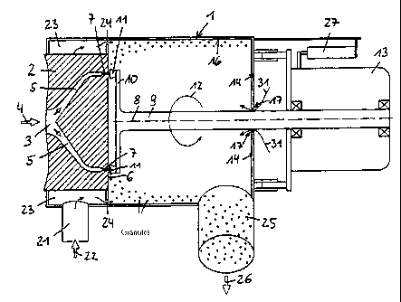
The advantageous embodiment form of an apparatus according to figure 1
features a
cylindrical granulating housing 1 that is delimited on its side, particularly
the one facing an
extruder, by a perforated plate 2 and, on its opposite front face, by an end
wall 14. In the perforated
plate 2 is a supply channel 3 provided for the plasticized material to be
granulated or the melt, in
particular thermoplastic resin material, that flows in the direction of the
arrow 4 from the supply
channel 3 into several distributor channels 5 that end on the front face 6 of
the perforated plate 2
in nozzles 7 that are disposed in a circle and at even spacings around the
central longitudinal axis
8 of the granulating housing 1.
This longitudinal axis 8 forms at the same time the rotation axis of a shaft 9
that supports
on its end that is facing the perforated plate 2 a knife head 10 that is
equipped with a plurality of
knifes 11 that during the rotation of the shaft 9 about its axis in the
direction of the arrow 12 graze
over the openings of the nozzles 7 and thereby knock off to granulate
particles the strand-like
plastic mass that is pressed out of the nozzles 7. The rotation of the shaft 9
is effected by a motor
13 that is disposed outside of the granulating housing 1 behind the end wall
14.
In order to assure that the knifes 11 always graze across the openings of the
nozzles 7 with
the desired contact pressure or the optimal cutting pressure the shaft 9 is in
the case of the present
embodiment form, in particular including the motor 13 that drives it, movable
or adjustable in the
axial direction of the longitudinal axis 8 relative to the granulating housing
1. This purpose in this
case serves an adjustment apparatus 27 that can be implemented by an actuator
of an arbitrary kind,
for example via threads, a magnet, by means of an actuator motor etc. In the
radial direction the
CA 02744983 2014-12-05
7
shaft 9 is not or not significantly movable. The adjustment apparatus in the
case of the embodiment
form according to figure 1 is attached to the granulating housing 1 and
engages the housing of the
motor 13, the axial adjustment capability of the shaft 9 can however also be
implemented
differently.
During operation a cooling medium, in particular cooling water or a mixture of
water and
glycol, is introduced into the interior of the granulating housing 1. This
cooling water is supplied
tangentially via a line 21 in the direction of the arrow 22 and flows into a
ring-shaped space 23 that
surrounds the perforated plate 2, from said space it enters through at least
one opening 24 into the
interior of the granulating housing 1, sweeps along the interior side of the
wall 16 in the form of a
water film or water ring and thereby picks and cools the granulate particles
that were knocked off
by the knifes 11 immediately after their creation, so that a baking-together
of these particles is
prevented. The cooled granulate particles are discharged together with the
cooling water via the
discharge line 25 in the direction of the arrow 26 from the granulating
housing I.
In the case of the apparatus according to figure 1 this concerns primarily a
known
granulating hot cut apparatus wherein the removal of the granulate particles
takes place by means
of the rotating water film.
The shaft 9 penetrates the granulating housing 1 in the central middle area of
the end wall
14. The shaft 9 is not supported in the end wall 14 of the granulating housing
1 but is primarily
supported by the motor 13. The shaft 9 penetrates the granulating housing 1
free of contact and
therefore friction-free or is spaced apart from the granulating housing 1.
The area between the shaft 9 and the granulating housing 1 if free of a
dragging sealing,
meaning no sealing is present in this area and namely neither sealing rings
nor greasing mean films
or such like. Between the interior of the granulating housing 1 and the outer
environment a
permanently open flow-through opening 17 is therefore implemented through
which air can flow
according to arrow 31 from the outside into the interior of the granulating
housing 1. The flow-
through opening 17 abuts immediately against the shaft 9 or leads directly
along the shaft 9 or the
shaft 9 is encompassed by the flow-through opening 17 completely and from all
sides in a cylinder-
casing shape. The flow-through opening 17 features the form of a cylinder ring
or a ring gap or an
open space of such kind is recessed.
CA 02744983 2014-12-05
8
By means of the discharge of the flowing cooling medium out of the granulating
housing
1 (arrow 26) or the relatively quick water flow, in particular at discharge
25, a certain vacuum in
comparison to the outer environment is implemented in the granulating housing
1 analogous to a
water jet pump. The vacuum is also influenced by the design of the discharge
25 and the
conveyance of the cooling medium in a sealed system, for example a hose.
Alternatively or in addition the vacuum could also be at least partially or in
support be
produced via a switchable vacuum pump. The granulating housing 1 therefore has
to exhibit a
certain stability against light to medium vacuum.
By means of this vacuum the surrounding air is drawn according to arrow 31
from the
outside through the flow-through opening 17 along the shaft 9 into the
interior of the granulating
housing 1. By means of this air current 31 that is directed toward the
interior, the cooling medium
cannot escape through the flow-through opening 17 against the air current 31
to the outside. It has
surprisingly turned out that this principle functions satisfactorily already
at very low vacuum in the
granulating housing 1. The area where the shaft 9 penetrates the granulating
housing 1 is therefore
sealed against the escape of cooling medium, whereby in this area the
application of expensive and
failure-prone seals can be omitted.
In figure 2 a further advantageous alternative implementation of the apparatus
is
represented. This one coincides for the most part with the apparatus according
to figure 1. On the
end wall 14 in the interior of the granulating housing 1 in the area of the
penetration of the shaft 9
into the granulating housing 1 is however disposed a flange element 19 that
encompasses the shaft
9 in a ring-shaped manner, wherein the flow-through opening 17 is implemented
in this flange
element 19 and surrounds the shaft 9 in a cylinder casing shape or cylinder-
shaped manner from
all sides. The shaft 9 touches neither the granulating housing 1 nor the
flange element 19 and runs
as such completely contact-less and therefore friction-free and wear-free and
spaced apart from the
granulating housing 1 and/or the flange element 19.
In the flow-through opening 17 and namely surrounded by the flange element 19
a back-
flow thread 30 that encompasses the shaft 9 in a cylinder casing shape or
cylinder-shaped manner
is disposed. This back-flow thread 30 abuts in contact-less manner spaced
apart or at best slightly
dragging against the shaft 9 and conveys toward the interior in the direction
of the granulating
housing 1. By these means residual water can be removed or a type of failure
protection is created,
in case the vacuum in the granulating housing 1 is too low or fails
intermittently. The air through-
CA 02744983 2014-12-05
9
flow is not significantly impeded by the back-flow thread 30 or a permanently
open flow-through
opening 17 is still provided.
The granulating housing 1 is designed in such a manner that possible leaks of
the
granulating housing 1 are so minor that during operation sufficient air is
always drawn into the
interior of the granulating housing 1 and a sufficiently strong air current is
provided through the
flow-through opening 17 in order to prevent an escape or penetration of water
through the flow-
through opening 17. In particular it is advantageous if the granulating
housing I is implemented
during operation, aside from the flow-through opening 17 and the supply and
discharge lines 21,
25 for the cooling medium, in a gas tight manner.