Note : Les descriptions sont présentées dans la langue officielle dans laquelle elles ont été soumises.
CA 02745651 2013-05-29
- 1 -
"PLANT FOR PACKAGING CONFECTIONARY PRODUCTS IN A STERILE
MANNER"
TECHNICAL FIELD
The present invention relates to a plant for packaging
confectionary products in a sterile manner in sterile
containers or packages.
In the foodstuffs industry, in general, and in the field of
packaging of confectionary products in sterile containers, in
particular, there is felt the need to package products in
containers having formats different from one another. For said
purpose, for each format, i.e., for each type of container,
there is currently used a packaging plant "dedicated" to the
specific container.
Each of said plants, commonly known as "form/fill/seal", and
disclosed for example, in US 3,911,640, comprises a plurality
of stations, which are aligned with one another along a
packaging path and are all housed within a common tunnel that
defines a "sterile" area or rather an area controlled in its
degree of bacteriological contamination in order to ensure the
sterility of the packaging. Fed step by step through the
aforesaid stations is a first thermoformable strip, which
defines an end wall of the tunnel and, after being sterilized,
is heated, in a purposely designed station, and then passes
into a thermoforming station for making one or more housings
or compartments designed to receive, each, at least one of the
aforesaid products. The compartments with the products to be
packaged inside are then sealed by means of a second strip
that is also previously sterilized and that delimits at the
top a terminal length of the aforesaid tunnel and is heat-
sealed on the first strip before the various compartments are
physically separated from one another in a dinking station.
CA 02745651 2013-05-29
- 2 -
BACKGROUND ART
Even though the known plants of the type described above are
currently in use, since they are dedicated to a given
container, they present a "rigid" configuration and
consequently cannot be drastically modified for producing
containers that may even be very different from the ones
originally envisaged. It is, however, possible to make partial
modifications to the known plants, said modifications in any
case requiring particularly long adaptation times and
generating unacceptable losses in terms of downtime of the
plant and, hence, of lack of production.
Furthermore, in known plants, precisely because they are
dedicated, the width of the strips and the step of advance of
the strips themselves are already determined in the design
stage and optimized as a function of the dimensions, geometry
and, in general, type of individual format or container
originally conceived so that the change in format inevitably
generates an increase in waste, i.e., in the amount of strips
not used in the processes of thermoforming and/or closing, to
= such an extent as to render production less economically
advantageous given, as is known, the high incidence of the
cost of the strips on the overall cost of the packaged
product.
The use of strips of different width on existing plants is
ruled out by the fact that the strips delimit the sterile area
and for this reason must be constantly coupled in a sealed way
to a wide range of mechanical components of the plant, which
would, in turn, have to undergo modifications or adaptations
that entail insurmountable difficulties. For the reasons set
forth above, each substantial change of format of the
containers requires replacement of the entire packaging plant.
Change of format of the containers is possible using the
adjustable plant disclosed in DE 20305759U1.
CA 02745651 2013-05-29
=
- 3 -
DISCLOSURE OF INVENTION
The aim of the present invention is to provide a plant for
packaging confectionary products in sterile containers, the
constructional characteristics of which enable a simple and
inexpensive solution of the problems set forth above.
According to the present invention a plant for packaging
confectionary products in sterile containers is provided, the
plant comprising, arranged along a packaging path, at least
one first assembly for sterilization and heating of a first
thermoformable strip, a forming assembly for making on said
first strip at least one compartment for housing said
confectionary products, an assembly for feeding a
confectionary product into said compartment, a second assembly
for sterilization and feed of a second closing strip towards
said first strip, a welding sealing assembly for connecting
together said strips and closing said confectionary product
within said housing compartment, a cutting assembly for
cutting said strips and making at least one said container,
and a sterile duct extending along said packaging path and
designed to contain a sterile gas, said duct being common to
said assemblies and being delimited at least partially by said
strips, the plant being characterized in that each said
assembly forms part of a respective operating module that is
independent of the other modules and coupled to the adjacent
modules in a releasable way.
Preferably, in the plant defined above, each said module
comprises a respective supporting frame that is independent of
the supporting frames of the other modules, the frames
supporting respective operating means designed to perform the
specific function of said module and part of the frames
themselves a respective half-shell casing distinct from the
other casings and connected to the adjacent casings via
releasable sealing means; each said casing delimiting a
respective length of said sterile duct.
CA 02745651 2013-05-29
- 4 -
BRIEF DESCRIPTION OF THE DRAWINGS
The invention will now be described with reference to the
attached figures, which illustrate a non-limiting example of
embodiment thereof and in which:
Figure 1 is a schematic perspective view of a preferred
embodiment of the plant according to teachings of the present
invention;
Figure 2 is similar to Figure 1 and illustrates the plant
broken down into some of its constitutive elements;
Figure 3 illustrates, at an enlarged scale, a detail of
Figures 1 and 2; and
Figure 4 illustrates, in perspective view, a component of the
plant of Figures 1 and 2.
BEST MODE FOR CARRYING OUT THE INVENTION
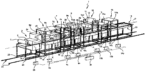
In Figure 1, designated as a whole by 1 is a plant for
packaging confectionary products in sterile containers. Here
and in what follows by the term "confectionary products" is
meant both products in a solid or granular form and products
in the form of a liquid or a cream.
The plant 1 has a modular composition or is made up of units
that are mutually independent, i.e., autonomous from the
mechanical, electrical, electronic, pneumatic, and management
standpoints. In the specific case, the plant 1 comprises, in
succession along a packaging path P, a module 3 for feed and
sterilization of a thermoformable strip 4, which is wound off
a spool 5 and fed step by step along the packaging path P by
drawing devices, which are known and not described in detail.
The plant 1 then comprises a module 6 for heating of the
thermoformable strip 4 and a module 7 for thermoforming of the
thermoformable strip 4 itself. The module 7 provides on the
strip 4 a plurality of housings or compartments 8 having
dimensions and relative positioning determined in the design
stage according to the product, the type of container to be
CA 02745651 2013-05-29
- 5 -
made, and the width of the strip 4 itself.
Downstream of the module 7, in the direction of advance of the
strip 4, the plant 1 further comprises a dispensing module 9
for feeding the product to be packaged into each of the
housings or compartments 8, and a further module 10 for feed
and sterilization of a heat-sealable strip 11 that can be
wound off a spool 12 carried by the module 10 itself.
Downstream of the module 10, the plant 1 further comprises a
welding module 13 for welding the strip 11 onto the portion of
the strip 4 not involved the previous thermoforming process so
as to close in a fluid-tight way each of the housings or
compartments 8, and a dinking module 14 for separating the
various housings or compartments 8 from one another to form a
plurality of sterile containers, which are fed towards an
outlet 15 of the plant 1 by a conveyor belt 16 that forms part
of the dinking module 14 itself.
Each of the modules 3, 6, 7, 9, 10, 13 and 14 comprises a
respective operating assembly, which is in itself known; said
assemblies are designated by 3a, 6a, 7a, 9a, 10a, 13a and 14a,
respectively. The operating assemblies are pneumatically
connected to a pneumatic source via dedicated valve assemblies
of their own (not illustrated) and electrically connected to
respective electronic control units 3b, 6b, 7b, 9b, 10b, 13b
and 14b. The electronic control units 3b, 6b, 7b, 9b, 10b, 13b
and 14b are each dedicated exclusively to the corresponding
operating assembly 3a, 6a, 7a, 9a, 10a, 13a and 14a, are
independent of one another, and are, in turn, electrically
connected and controlled by a general control unit 18 for
managing the entire plant 1.
Each module 3, 6, 7, 9, 10, 13 and 14 further comprises a
respective structure or frame 3c, 6c, 7c, 9c, 10c, 13c and 14c
for supporting the corresponding operating assembly 3a, 6a,
7a, 9a, 10a, 13a and 14a and the various electrical and
CA 02745651 2013-05-29
- 6 -
pneumatic wiring/components; each frame 3c, 6c, 7c, 9c, 10c,
13c and 14c is separate from and independent of the other
frames and is set alongside and coupled to the frames adjacent
thereto in a releasable way, for example via fast-coupling
assemblies (not visible in the attached figures). Each frame
3c, 6c, 7c, 9c, 10c, 13c and 14c is supported by a guide-and-
slide assembly of its own, comprising a slide defined by a
plurality of bottom resting feet or portions 20 (Figures 1 and
3) of the respective frame itself; in the particular example
described, the portions 20 have respective bottom terminal
seats 21 shaped like a U set upside down and engaged by a
corresponding rectilinear guide 22 in a slidable way. The
guide 22 forms part of the aforesaid guide-and-slide assembly
and part of a rail 23 for relative positioning, which is
common to all the modules 3, 6, 7, 9, 10, 13 and 14, extends
parallel to the path P, and is stably fixed on the floor. In
this way, each of the modules 3, 6, 7, 9, 10, 13 and 14 can be
translated along the rail 23 and hence along the aforesaid
packaging path P independently of the other modules and, in
particular, can be uncoupled from the rail 23 itself and moved
away by simple vertical lifting, as illustrated for the module
9 in Figure 2. AlternatiJely, according to a variant not
illustrated, one or more modules have their respective frames
arranged, each, on a respective motor-driven trolley or other
equivalent means for movement of the module, designed to be
controlled in position independently of the other trolleys,
for displacement in a direction transverse to the aforesaid
packaging path P, between an operative advanced position, in
which the corresponding frame extends along the path P in a
pre-determined position, and an extracted position, in which
the frame is set outside of the packaging path P and in which
the module does not take part in the packaging process.
Each of the frames supports an intermediate resting surface K,
which is substantially coplanar to the surfaces K of the other
frames, and on which the thermoformable strip 4 rests during
= CA 02745651 2013-05-29
- 7 -
its advance towards the outlet 15. In this way, the various
surfaces K define at least part of a sliding guide for the
thermoformable strip 4. At output from the dinking assembly
14, the containers are moved away via the conveyor belt 16.
Each of the frames arranged upstream of the sealing assembly
13 moreover supports a respective half-shell 3d, 6d, 7d, 9d
and 10d, which is set only above the corresponding resting
surface K with its concavity facing the corresponding plane
surface K itself and is coupled to the half-shells adjacent to
it in a releasable way via the interposition of respective
gaskets or labyrinth seals designated by 25. In the particular
example described, each half-shell 6d, 7d, 9d and 10d
comprises a corresponding top wall 26 set facing, and
superimposed only on, the corresponding plane resting surface
K and vertically raised with respect to the corresponding
plane surface K itself, and two side walls 27, which face one
another and extend upwards once again starting from the
respective flat resting surface K. Each of the top walls 26
has a size measured parallel to the corresponding surface K
and orthogonal to the path P that can be varied as a function
of the width of the thermoformable strip 4 and of the strip 11
and a through opening traversed by a mobile element of the
respective operating assembly 6a, 7a, 9a, 10a. The side walls
27 terminate, instead, in the direction of the corresponding
resting surface K, with respective portions, which, in the
case in point, are L-shaped (Figures 2 and 4), to which the
opposite longitudinal lateral portions of the thermoformable
strip 4 are coupled in a slidable way so as to guarantee
maintenance of an overpressure of the sterile environment
within the tunnel. In this way, each half-shell 6d, 7d, 9d and
10d delimits, with a corresponding intermediate portion of the
thermoformable strip 4, a respective length of a continuous
tunnel 30 (Figure 4), which is closed upstream by the feed and
sterilization assembly 3 and downstream by the closing strip
11, which progressively converges towards the underlying
CA 02745651 2013-05-29
=
- 8 -
thermoformable strip 4 before being welded to the
thermoformable strip 4 itself. Supplied into the tunnel 30 is
sterile air and, in general, a sterile gas containing nitrogen
at a variable pressure of between 0.01 and 1 bar to create a
sterile environment, in which all the packaging operations are
performed.
From the foregoing description, it is evident how the
constructional characteristics of the plant 1 described and,
in particular, the fact of using a plurality of modules or
units completely independent of one another and autonomous
from the mechanical, electrical, electronic, pneumatic, and
management or control standpoints, but that can be coupled to
one another in a functional way enables, according to the
needs, transformation in an extremely fast way and hence with
reduced downtimes, of an existing packaging plant into a new
plant for packaging a different type of product or for the
production of different containers, maintaining the efficiency
and reliability of the previous plant unvaried but, above
all, reducing to a minimum the machining waste. What has just
been set forth is basically the result of the fact that each
one of the modules that make up the plant 1 is perfectly
interchangeable or replaceable with another functionally
equivalent module, i.e., a module that performs the same
function as the replaced module and can be chosen from among a
plurality of modules having constructional characteristics
different from one another. By the term "constructional
characteristics" is meant the characteristics of the module
that enable variation of the type, i.e., geometry and/or
dimensions, of the containers produced.
Furthermore, other features remaining the same, the fact of
envisaging, for each of the modules 6,7,9 and 10, a
corresponding adjustable half-shell for forming the sterile
environment enables arbitrary variation of the transverse
dimensions of the tunnel 30 and makes it hence possible to use
CA 02745651 2016-02-09
- 9 -
thermoformable and closing strips of different width. In the
particular example described, in fact, the half-shells
provided enable use of thermoformable and closing strips of
widths that vary in a percentage of 15-% with respect to a
given width and hence optimization of the surface of the
thermoformable strip 4, reducing to a minimum the waste
resulting from dinking.
Finally, the fact of using a common guide rail and of coupling
the different modules to the same rail in an axially slidable
way makes it possible, on the one hand, to ensure always a
precise positioning of the modules along the path P of
advance, and on the other, to replace any of the modules by
simply sliding the others along the rail. Furthermore, sliding
along the rail enables replacement of an existing module with
another module having a different longitudinal dimension,
i.e., a dimension measured in the direction of the packaging
path. In other words, the new module may be positioned in a
space not necessarily identical to the one left free by the
previous module. Furthermore, said implementation enables
insertion of additional modules that are able to satisfy
different working processes, e.g., working processes that
comprise a number of a dispensing station.
From the foregoing description it emerges clearly that
modifications and variations may be made to the plant 1
described in the present application.
In particular, the plant 1 could comprise a number of modules
different from the one indicated by way of example, and said
modules could present frames or shapes that differ from the
ones indicated once again by way of example.
Furthermore, the half-shells for obtaining the sterile
environment could be provided in a way different from the one
CA 02745651 2013-05-29
- 10 -
indicated by way of example once again in the perspective of
facilitating transformation of the plant according to the
widths of the strips to be used.