Sélection de la langue

Search

Sommaire du brevet 2746178 

Énoncé de désistement de responsabilité concernant l'information provenant de tiers

Une partie des informations de ce site Web a été fournie par des sources externes. Le gouvernement du Canada n'assume aucune responsabilité concernant la précision, l'actualité ou la fiabilité des informations fournies par les sources externes. Les utilisateurs qui désirent employer cette information devraient consulter directement la source des informations. Le contenu fourni par les sources externes n'est pas assujetti aux exigences sur les langues officielles, la protection des renseignements personnels et l'accessibilité.

Disponibilité de l'Abrégé et des Revendications

L'apparition de différences dans le texte et l'image des Revendications et de l'Abrégé dépend du moment auquel le document est publié. Les textes des Revendications et de l'Abrégé sont affichés :

  • lorsque la demande peut être examinée par le public;
  • lorsque le brevet est émis (délivrance).
(12) Demande de brevet: (11) CA 2746178
(54) Titre français: EXTENSEUR POUR L'INSTALLATION DE L'EMBOUT FIXE D'UN STORE A ROULEAU SUR UN TUBE DE ROULEMENT
(54) Titre anglais: EXPANDER FOR MOUNTING AN IDLE END OF A ROLLER BLIND TO A ROLLER TUBE
Statut: Réputée abandonnée et au-delà du délai pour le rétablissement - en attente de la réponse à l’avis de communication rejetée
Données bibliographiques
Abrégés

Abrégé anglais


There is provided a system for correcting errors in cutting the length of a
roller tube by
effectively expanding the length of the roller tube which is to be mounted to
an idle end to form
a roller blind. The system includes at least one flat disk coaxially mounted
between the idle end
and one end of the roller tube. The flat disk has a thickness equal to a
desired length of
expansion of the roller tube. The flat disk has a central opening dimensioned
to receive the idle
end.

Revendications

Note : Les revendications sont présentées dans la langue officielle dans laquelle elles ont été soumises.


Therefore, what is claimed is:
1. A system for effectively expanding the length of a roller tube mounted to
an idle end,
the system comprising at least one flat disk coaxially mounted between the
idle end
and one end of the roller tube, the flat disk having a thickness equal to a
desired
length of expansion of the roller tube, the flat disk having a central opening
dimensioned to receive the idle end.
2. The system for effectively expanding the length of a roller tube as defined
in claim 1
further comprising a plurality of identical flat disks, each of the flat disks
having a
thickness equal to the desired length of expansion divided by the number of
identical
flat disks.
3. The system for effectively expanding the length of a roller tube as defined
in claim 1
wherein the idle end has a barrel portion, a flange portion and a plurality of
fins
radiating from the barrel portion and wherein the flat disk includes a central
opening
dimensioned and configured to receive the barrel portion, the central opening
further
comprising a plurality of slots configured to receive the fins.
4. The system for effectively expanding the length of a roller tube as defined
in claim 2
wherein the idle end has a barrel portion, a flange portion and a plurality of
fins
radiating from the barrel portion and wherein the flat disk includes a central
opening
dimensioned and configured to receive the barrel portion, the central opening
further
comprising a plurality of slots configured to receive the fins.
6

5. The system for effectively expanding the length of a roller tube as defined
in claim 3
further comprising a plurality of identical flat disks, each of the flat disks
having a
thickness equal to the desired length of expansion divided by the number of
identical
flat disks.
6. The system for effectively expanding the length of a roller tube as defined
in claim 4
wherein the fins have a length which is longer than the combined thicknesses
of the
flat disks.
7. The system for effectively expanding the length of a roller tube as defined
in claim 3
wherein the fins have a length which is longer than the combined thicknesses
of the
flat disks.
7

Description

Note : Les descriptions sont présentées dans la langue officielle dans laquelle elles ont été soumises.

CA 02746178 2011-07-13
TITLE: EXPANDER FOR MOUNTING AN IDLE END OF A ROLLER BLIND TO A
ROLLER TUBE
FIELD OF THE INVENTION
The invention relates generally to roller blinds and in particular idle ends
for mounting an
end of a roller blind tube to a mounting bracket
BACKGROUND OF THE INVENTION
Roller blinds always include an elongated roller tube having opposite ends
which is
mounted between support brackets. The support brackets are generally suspended
at the top of a
window frame so that the roller blind drapes over the window. The roller blind
generally has a
clutch end positioned at one end of the roller tube and an idle end positioned
at the opposite end
of the roller tube. The roller tube is suspended to the support brackets at
the clutch end and idle
end.
Installing a roller blind often starts by measuring the width of the window
and cutting the
roller tube to match the width of the window. The roller tube is generally an
elongated
aluminum tube which can be easily cut at the installation site. It will be
appreciated that given
the long length of the desired roller tube, it is quite possible to make a
small error in the
measuring or cutting of the roller tube. Generally, measuring and cutting
errors range between a
few millimeters to a few centimeters. If the roller tube is accidentally cut
two centimeters too
long, it is a trivial matter to shorten the roller tube. However, if the
roller tube is cut two
centimeters too short, then the wrongly cut piece of roller tube will have to
be discarded. In
addition to wasting the material cost of the discarded section of roller tube,
cutting the roller tube
1

CA 02746178 2011-07-13
too short can seriously decrease the efficiency of the installation because
time will be wasted in
mounting a wrongly sized roller tube. A system which would correct cutting
errors in roller
tubes would therefore decrease costs and increase efficiency.
SUMMARY OF THE INVENTION
In accordance with one aspect of the present invention, there is provided a
system for
correcting errors in cutting the length of a roller tube by effectively
expanding the length of a
roller tube which is to be mounted to an idle end to form a roller blind. The
system includes at
least one flat disk coaxially mounted between the idle end and one end of the
roller tube. The
flat disk has a thickness equal to a desired length of expansion of the roller
tube. The flat disk
has a central opening dimensioned to receive the idle end.
With the foregoing in view, and other advantages as will become apparent to
those
skilled in the art to which this invention relates as this specification
proceeds, the invention is
herein described by reference to the accompanying drawings forming a part
hereof, which
includes a description of the preferred typical embodiment of the principles
of the present
invention.
DESCRIPTION OF THE DRAWINGS
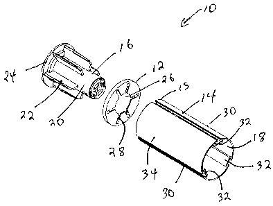
Figure 1 is a perspective view of an idle end expander made in accordance with
the present
invention for use with an idle end and a roller tube.
Figure 2 is a perspective view of two idle end expanders made in accordance
with the present
invention for use with an idle end and a roller tube.
2

CA 02746178 2011-07-13
Figure 3 is a side view of an idle end coupled to a roller tube without the
spacer portion of the
present invention.
Figure 4 is a side view of two idle end expanders made in accordance with the
present invention
and mounted between an idle end and a roller tube.
Figure 5 is a side view of an idle end expander made in accordance with the
present invention for
use with an idle end and a roller tube.
Figure 6 is a side view of two idle end expanders made in accordance with the
present invention
for use with an idle end and a roller tube.
In the drawings like characters of reference indicate corresponding parts in
the different
figures.
DETAILED DESCRIPTION OF THE INVENTION
Referring firstly to figures 1 and 2, an expander system for use with a roller
tube and idle
end is shown generally as item 10 and consists of a flat circular member 12
which is configured
to mount coaxially between idle end 16 and roller tube 14 so as to compensate
for the roller tube
being too short. Roller tube 14 is generally an elongated extruded aluminum
tube having an
interior 18 and an outside surface 34. Grooves 30 are formed on the outside
surface 34 of roller
tube 14 and channels 32 project into interior 18. The length of roller tube 14
is generally several
feet and is cut to suite the length of the desired roller blind (not shown)
which is to be made
using the roller tube. Idle end 16 is dimensioned to fit within end 15 of
roller tube 14. Idle end
16 has barrel portion 20, flange portion 24 and a plurality of fins 22
radiating from barrel portion
20. Fins 22 are dimensioned to permit idle end 16 to fit snuggly within
interior 18 of roller tube
14. Fins 22 are spaced apart such that channels 32 fit between adjacent fins
to permit the idle
3

CA 02746178 2011-07-13
end to fit all the way in roller tube 14 such that flange 24 lies flush
against end 15. Spacer 12 is a
disc shaped plastic member having an external diameter equal to the external
diameters of roller
tube 14 and flange portion 24 of idle end 16. Spacer 12 has central opening 26
which is
dimensioned and configured to fit over and receive barrel portion 20 of idle
end 16. Slots 28 are
formed in spacer 12 and configured such that they can be aligned with and
receive fins 22 of idle
end 16. When idle end 16, spacer 12 and roller tube 18 are coaxially aligned,
spacer 12 can be
snuggly fitted between flange 24 and end 15, thereby effectively lengthening
roller tube 14 by
the thickness of spacer 12. As best seen in figure 2, it is possible to
further increase the effective
length of roller tube 14 by using a plurality of identical spacers. The length
by which roller tube
14 is increased is a sum of the thicknesses of the spacers used.
Referring now to figure 3, without spacer 12, idle end 16 can be mounted to
end 15 of
roller tube 14 such that flange portion 24 of the idle end snuggly abuts end
15. This is the
configuration which is likely to be used in the event that roller tube 14 is
cut to the correct size
and need not be expanded. As best seen in figure 4, each spacer 12 has a
thickness 36. As shall
be discussed below, preferably, thickness 36 is selected to be between 2 mm to
6 mm. Adding
one spacer 12 increases the effective length of roller tube 14 by the amount
of thickness 36.
Adding several spacers increases the effective length of roller tube 14 by the
cumulative total
thicknesses of all the spacers. Hence, in the example shown in figure 4, if
each spacer 12 has a
thickness of 5mm, then the effective length of roller tube 14 will be
increased by 1 cm.
Spacers 12 are intended to be used in order to correct measuring errors when
roller tube
14 is cut. It has been discovered that a majority of cutting/measuring errors
are in the range of
only one or two centimeters. Since the actual cutting error is essentially
random, each spacer is
preferably in the range of between 2 to 6 mm in thickness to enable one or two
standardized
4

CA 02746178 2011-07-13
spacer sizes to be used. This eliminates the need for carrying a plurality of
different sized
spacers. As seen in figures 5 and 6, fins 22 of idle end 16 have a length 38
of over 4 centimeters,
which is significantly longer than similar fins on standard idle end used with
roller blinds. The
increased length of fins 22 is to accommodate a larger number of spacers 12
and therefore enable
several spacers to be mounted to the idle end. It will be appreciated that
spacers 12 do not help
secure end 15 of roller tube 14. Roller tube 14 is supported on fins 22, so
adding several spacers
12 between flange 24 and end 15 actually decreases the amount of contact
between fins 22 and
the roller tube. To compensate for this decreased contact between fins 22 and
roller tube 14, fins
22 are made several centimeters longer to ensure that sufficient contact
between the roller tube
and the idle end is maintained even when several spacers 12 are used.
A specific embodiment of the present invention has been disclosed; however,
several
variations of the disclosed embodiment could be envisioned as within the scope
of this invention.
It is to be understood that the present invention is not limited to the
embodiments described
above, but encompasses any and all embodiments within the scope of the
following claims
5

Dessin représentatif
Une figure unique qui représente un dessin illustrant l'invention.
États administratifs

2024-08-01 : Dans le cadre de la transition vers les Brevets de nouvelle génération (BNG), la base de données sur les brevets canadiens (BDBC) contient désormais un Historique d'événement plus détaillé, qui reproduit le Journal des événements de notre nouvelle solution interne.

Veuillez noter que les événements débutant par « Inactive : » se réfèrent à des événements qui ne sont plus utilisés dans notre nouvelle solution interne.

Pour une meilleure compréhension de l'état de la demande ou brevet qui figure sur cette page, la rubrique Mise en garde , et les descriptions de Brevet , Historique d'événement , Taxes périodiques et Historique des paiements devraient être consultées.

Historique d'événement

Description Date
Demande non rétablie avant l'échéance 2016-07-13
Le délai pour l'annulation est expiré 2016-07-13
Réputée abandonnée - omission de répondre à un avis sur les taxes pour le maintien en état 2015-07-13
Requête visant le maintien en état reçue 2014-07-11
Requête visant le maintien en état reçue 2013-07-03
Inactive : Page couverture publiée 2013-01-22
Demande publiée (accessible au public) 2013-01-13
Inactive : CIB en 1re position 2011-10-24
Inactive : CIB attribuée 2011-10-24
Inactive : Certificat de dépôt - Sans RE (Anglais) 2011-07-28
Demande reçue - nationale ordinaire 2011-07-28
Déclaration du statut de petite entité jugée conforme 2011-07-13

Historique d'abandonnement

Date d'abandonnement Raison Date de rétablissement
2015-07-13

Taxes périodiques

Le dernier paiement a été reçu le 2014-07-11

Avis : Si le paiement en totalité n'a pas été reçu au plus tard à la date indiquée, une taxe supplémentaire peut être imposée, soit une des taxes suivantes :

  • taxe de rétablissement ;
  • taxe pour paiement en souffrance ; ou
  • taxe additionnelle pour le renversement d'une péremption réputée.

Les taxes sur les brevets sont ajustées au 1er janvier de chaque année. Les montants ci-dessus sont les montants actuels s'ils sont reçus au plus tard le 31 décembre de l'année en cours.
Veuillez vous référer à la page web des taxes sur les brevets de l'OPIC pour voir tous les montants actuels des taxes.

Historique des taxes

Type de taxes Anniversaire Échéance Date payée
Taxe pour le dépôt - petite 2011-07-13
TM (demande, 2e anniv.) - petite 02 2013-07-15 2013-07-03
TM (demande, 3e anniv.) - petite 03 2014-07-14 2014-07-11
Titulaires au dossier

Les titulaires actuels et antérieures au dossier sont affichés en ordre alphabétique.

Titulaires actuels au dossier
Z.M.C. METAL COATING INC.
Titulaires antérieures au dossier
NORMAN WILLS
Les propriétaires antérieurs qui ne figurent pas dans la liste des « Propriétaires au dossier » apparaîtront dans d'autres documents au dossier.
Documents

Pour visionner les fichiers sélectionnés, entrer le code reCAPTCHA :


Pour visualiser une image, cliquer sur un lien dans la colonne description du document. Pour télécharger l'image (les images), cliquer l'une ou plusieurs cases à cocher dans la première colonne et ensuite cliquer sur le bouton "Télécharger sélection en format PDF (archive Zip)" ou le bouton "Télécharger sélection (en un fichier PDF fusionné)".

Liste des documents de brevet publiés et non publiés sur la BDBC .

Si vous avez des difficultés à accéder au contenu, veuillez communiquer avec le Centre de services à la clientèle au 1-866-997-1936, ou envoyer un courriel au Centre de service à la clientèle de l'OPIC.


Description du
Document 
Date
(aaaa-mm-jj) 
Nombre de pages   Taille de l'image (Ko) 
Description 2011-07-12 5 176
Dessins 2011-07-12 6 70
Abrégé 2011-07-12 1 11
Revendications 2011-07-12 2 47
Dessin représentatif 2012-03-22 1 13
Certificat de dépôt (anglais) 2011-07-27 1 156
Rappel de taxe de maintien due 2013-03-13 1 112
Courtoisie - Lettre d'abandon (taxe de maintien en état) 2015-09-07 1 172
Rappel - requête d'examen 2016-03-14 1 116
Taxes 2013-07-02 1 31
Correspondance 2014-05-29 1 26
Taxes 2014-07-10 2 60