Note : Les descriptions sont présentées dans la langue officielle dans laquelle elles ont été soumises.
1
HAND CART BRAKING SYSTEM
[0001] Continue to [002].
BACKGROUND OF THE INVENTION
Field of the Invention
[0002] The present invention relates to a hand operated braking system for
a hand
cart. More particularly, the present invention includes a hand cart braking
system
with a single clutch braking system.
Summary of Related Art
[0003] Hand carts are well known in the material handling industry for
loading and
unloading material from trucks and trailers. Hands carts are used not only at
truck
loading docks, but also at retail establishments and other delivery points.
Hand carts
are also essential devices for moving loads within warehouses and production
facilities. The primary construction of a hand cart includes two wheels on a
single
axle, two vertical frame members with cross frame members, a handle at the top
of
the frame, and a load engaging flange plate at the bottom of the frame. A
typical
braking system for a hand cart is a hand operated system positioned on the
handle at
the top of the frame.
[0004] A significant problem which occurs during use of a hand cart is
controlling a
loaded hand cart on an inclined surface. Inclined surfaces are encountered
quite
frequently in many hand cart applications, such as maneuvering hand carts up
and
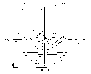
down truck unloading ramps. The inability to control a loaded hand cart on an
inclined surface frequently results in damage to the load being moved and
injury to
CA 2747528 2017-12-18
CA 02747528 2011-07-29
2
the person operating the hand cart.
[0005] When using a hand cart, the operator will frequently use only one
hand to
control the cart and the other hand is used to engage and steady the load
being
carried on the cart. Since the operator utilizes one hand on the load, the
braking
systems on hand carts are generally positioned at the handle and designed for
one
hand operation.
[0006] One of the problems with braking systems on hand carts is that the
braking
force should be applied uniformly to the two wheels. When the braking force is
applied unevenly, the hand cart will not roll in a straight path and will
swing to one
side. When an operator is applying the brake while rolling a loaded hand cart
down a
loading ramp, uniform braking to facilitate straight path operation is
essential.
[0007] Another requirement for hand cart operation is maneuverability.
Since
hand carts must be operable on a non-linear path when moving a load, it is
essential
that the braking system not adversely effect the maneuverability of the hand
cart.
Independent operation of the wheels is required to permit the hand cart to
turn
corners in a controlled manner.
[0008] A majority of hand carts do not have any braking capabilities and
the
person using the hand cart must use their own strength to stop and/or control
a cart
on an inclined surface. Several braking systems for hand carts are disclosed
in the
prior art. The hand carts of the prior art typically include independent
wheels and a
fixed axle which are mounted on a bracket or other mounting means on the lower
corners of the frame. A separate braking mechanism is required for each of the
wheels. One of the problems with the prior art systems has been achieving
uniform
braking force at the two wheels.
[0009] In the prior art, Honeyman (U.S. Patent No. 3,276,550) discloses an
U-
CA 02747528 2011-07-29
3
shaped brake rod mounted between the two wheels. Projecting ends are
positioned
above the wheels to form a braking means. When the handle is pulled, the
projecting
ends are positioned in front of the wheels such that a braking force is
applied to limit
the rotation of the wheels. The forward movement of the wheels tends to cause
greater engagement between the wheels and the projecting ends which creates a
self
actuating feature.
[0010] In attempting to improve the maneuverability of the hand cart during
braking, Malloy (3,486,587) discloses the benefits of having independent
operation of
the brakes with a single operating handle. A special linkage is attached to
the brake
shoes of the wheels to provide independent braking.
[0011] Wetzel (3,368,974) discloses wheels mounted by separate bearings
mounted on a fixed axle to provide for independent rotation. A hydraulic
system is
used to actuate a caliper-type disc brake system mounted at each of the
wheels.
Equal braking force is applied to each of the wheels. Boyd (4,142,732) teaches
a
disc braking system to brake the main axle shown in the specialized hand cart.
The
wheels are independently mounted on star-shaped plates, and the plates rotate
when
the cart is used on stairs. The hand brake system locks the main axle to
prevent the
plates from rotating.
[0012] Laird (4,819,767) discloses a braking system which can be used on
both
two-wheel and four-wheel hand carts. Brake discs are mounted in the frame and
are
selectively extended from the frame to engage the sidewalls of the wheels to
prevent
rotation of the wheels.
[0013] A hand cart having a brake drum mounted about the hub of the wheels
is
disclosed in Hedrick (5,390,943). The wheels operate independently. The brakes
are operated by a single handle with two separate brake actuating cables to
two
independent brakes. The stopping force to each wheel is equalized by a brake
CA 02747528 2011-07-29
4
adjusting screw on each brake.
[0014] Hlebakos (5,433,464) shows a braking system having wheels with a
braking shoe and backing plate assembly. A pulley system and cam followers are
used to provide equal braking pressure to each of the wheels. Such a braking
system is intended for retrofitting on existing hand carts.
[0015] The braking system disclosed in Grieg (5,524,731) teaches a brake
bar
mounted on the cart and extending between the two wheels of the cart. Brake
pads
are mounted on the brake bar which engage the wheels. A step plate is attached
to
the bar to permit the operator to tilt the hand cart into an operating
position.
[0016] Wyse (5,722,515) discloses a hand cart braking system having a
rotatable
split axle mounted laterally between the wheels of the hand cart. The axle is
split in
the middle of the axle to form two distinct segments. Each axle segment
rotates with
its respective wheel, and the axle segment and wheel on one side of the cart
rotate
independently of the other axle segment and wheel combination. A brake is
mounted
on the axle at the junction of the two axle segments. An actuator handle is
mounted
on the cart at a convenient point for actuating the brake. When the brake is
manually
operated, the braking force is applied to both segments of the axle to
smoothly stop
the hand cart. The brake is preferably a disc brake or a drum brake, although
other
braking devices may also be used in the present system. The brake utilizes a
double
clutch system to engage and disengage the brake.
SUMMARY OF THE INVENTION
[0017] According to the present invention, there is provided an improved
braking
system utilizing a single clutch assembly.
[0018] Instead of utilizing a double clutch assembly, the system utilizes a
split axle
with a single clutch. The axle extends through bearing mounted on a bearing
support
CA 02747528 2011-07-29
at the bottom of the hand cart. Each axle segment rotates with its respective
wheel,
and the axle segment and wheel on one side of the cart rotate independently of
the
other axle segment and wheel combination.
[0019] A brake is mounted on the axle at the junction of the two axle
segments.
An actuator handle is mounted on the cart at a convenient point for actuating
the
brake. A rod or cable extends from the handle along the frame of the cart to
the
brake mounted on the axle. When the brake is manually operated, the braking
force
is applied to both segments of the clutch to smoothly stop the hand cart. The
brake is
preferably a disc brake or a drum brake, although other braking devices may
also be
used in the present system.
[0020] The split axle facilitates the independent rotation of the two axle
pieces and
the wheels which are fixed at opposite ends of the axle. The split axle
provides
superior operating performance when moving the cart around a turn or in other
nonlinear applications. Upon application of the brake however, the axle
essentially
forms a unitary piece. This allows for greater control of the cart when the
brake is
being applied.
[0021] The axle is mounted on a bearing support frame or bracket which is
secured to the frame of the hand cart. The frame includes two bearings, one on
each
segment of the axle, to facilitate the rotation of the axle. The bearing
support bracket
includes a cross bar parallel to the split axle to provide a convenient foot
pad for use
in tilting the loaded hand truck.
[0022] The brake can be any type of brake to be mounted on the axle. Mounting
the brake at the junction of the axle segments permits the use of a single
actuator for
braking both axle segments. Drum brake and a disc brake are the two preferred
configurations for the system. Each axle segment is provide with a drum. The
friction
bands for engaging the drums are mounted about the drums between the brackets.
CA 02747528 2011-07-29
6
The friction bands can be activated by a single actuator. For a disc brake, a
disc is
welded to each of the axle segments and the friction pads are mounted about
the
discs.
[0023] With the single clutch system, a brake can be provided that has a
brake
pad on each side, or a brake pad on one side and a rotor on the other. Any
standard
braking material could be incorporated in embodiments of the present
invention.
[0024] An object of the present invention is to provide a hand cart braking
system
that provides an improved braking system that is cost effective. Many of the
braking
systems are very complex such that the costs would be unreasonable and too
expensive to gain wide spread acceptance in the industry. The present
invention is a
mechanically simplified system that performs at a high level, yet is
mechanically
simpler, and thus more cost effective than known braking systems. The system
also
provides an operating performance needed in hand truck applications on an
inclined
surface.
[0025] An object of the present invention is to provide a hand cart braking
system
which can be operated with one hand, yet still achieve even braking force at
both of
the wheels. In addition, the wheels of the cart must operate independently to
ensure
maneuverability to handle turns and curves.
[0026] A further object of the present invention is to design a braking
system that
can be used with a two wheel upright hand cart or a four wheel flat bed hand
cart.
[0027] An additional object of the present invention is to provide a
braking system
which can be mounted on existing hand carts. The axle and wheel mountings on
an
existing cart can be removed and the bearing support and axle of the present
invention can be mounted on the lower segment of the hand cart.
CA 02747528 2011-07-29
7
BRIEF DESCRIPTION OF THE DRAWINGS
[0028] The above, as well as other advantages of the present invention,
will
become readily apparent to those skilled in the art from the following
detailed
description of a preferred embodiment when considered in the light of the
accompanying drawings.
Figure 1 shows a cart with a known braking system; and
Figure 2 shows a braking system in accordance with an embodiment of the
present invention.
DESCRIPTION OF THE PREFERRED EMBODIMENT
[0029] Figure 1 shows a known hand cart with a brake system as known in the
art.
The braking system of the present invention is suitable for use in such a cart
as is
disclosed herein.
[0030] In FIG. 1, a known hand cart 10, which is suitable for use with the
present
invention, includes a braking system 12 mounted on the split axle 14 extending
between the wheels 16a, 16b of the hand cart 10. The hand cart 10 is formed by
two
elongated, parallel load supporting frame members 18 with cross members 20 and
center strut 22. A curved handle 24 is formed at the upper end of the frame
members
18. Various handle configurations are known in the industry to facilitate
operation of
the hand cart 10. The frame members 18 and cross members 20 are typically made
from steel or aluminum tubing or bars. An actuator bar 60 with a handle 62 is
used to
activate the brake system 12.
[0031] At the front, lower end of the frame members 18, a lifting blade 26
is
mounted to extend perpendicularly from the frame members 18. The lifting blade
26
accomplishes the dual function of lifting and supporting objects to be moved
by the
hand cart and of maintaining the hand cart in an upright position when not in
use.
CA 02747528 2011-07-29
8
[0032] The hand cart 10 includes a pair of laterally spaced wheels 16A,16B
mounted at the lower end of the vertical frame members 18. The wheel assembly
can be connected to the cart as is standard in the art. The wheels 16A, 16B
may be
furnished with any type of tire. Brakes are typically furnished on hand carts
used for
heavier loads, and such hand carts generally include pneumatic tires.
[0033] In the prior art, the typical hand cart included support members
with a
single fixed axle extending through the support members. At the end of the
fixed
axle, bearings or other rotational devices are used in the prior art to
rotatably connect
the wheels to the fixed axle such that the wheels have a fixed direction and
rotate
independently of one another.
[0034] In an embodiment of the present invention shown in Figure 2, two
arms 50
are rotatably mounted near the lower end of the vertical frame members 18.
Actuator
arms 70 are slidably connected to struts 18 at pivots 52, with the arms 50
connected
to the actuator arms 70. In a preferred embodiment arms 52 are fixed relative
to
actuator arms 70 so that when actuator arms 70 are displaced by actuator bar
60,
arms 50 move inward about pivot 72 towards each other. The arms 50 extend
inward
towards each other.
[0035] A split axle 54 extends from the first wheel to the opposite wheel,
and can
be mounted by systems known in the art.
[0036] The internal ends of each part of the split axle form a portion of
the braking
assembly. In one embodiment each interior end is fitted with a disc brake 56
each
with a brake pad 66. In another embodiment (not shown) of the present
invention
one of the ends is fitted with a brake pad and the other with a rotor. When
pressed
together, these internal ends lock the split axle 54 into a unitary single
axle.
CA 02747528 2011-07-29
9
[0037] The segments of the split axle are preferably of equal diameter and
would
generally be cut from the same stock of steel or other acceptable material.
The
length of the split axle segments are sized based on the width of the hand
cart and
the distance between the wheels. The axle segments are typically of equal
length
such that the split occurs in the middle of the overall axle length, but the
lengths of
the segments do not have to be equal in length for the brake system to
function
properly.
[0038] The axle segments are designed to facilitate independent rotation of
the
axle segments with respect to each other and their respective affixed wheels.
[0039] The braking action may be provided by any type of mechanical,
hydraulic, or electrical brake. In a preferred embodiment, a dual caliper
system 58
clamps onto two brakes 56 pushing them together. Each of the brakes 56 is
preferably affixed with a pad 66, so that they contact each other when the
brake is
applied, and each caliper 58 is preferably affixed with a pad 68, for
contacting the
respective exterior portion of the brake drum. A mounting rod 64 can extend
through
the interior of one of the axle segments 54 and align with a hole in the end
of the
other axle segment 54. This can help ensure proper alignment of the brake pads
when they are engaged.
[0040] The operator of the hand cart will often use one hand to secure a
load on
the load bearing member and use the other hand to control movement of the hand
cart. When operating the hand cart with one hand, the hand will usually be
positioned near the center of the handle at the top of the cart. A pull handle
actuator
can be configured near the center of the handle so that the operator can
activate the
brake system by pulling on the handle with the hand on the cart. The pull
handle can
be of any configuration known in the art. An extended bar handle, such as the
safety
handles used on power lawn mowers, would provide a convenient system for one-
handed operation of the hand cart and brake system. The pull handle does not
have
i
to be positioned near the center of the handle and can arranged in any
position on
the handle most convenient for the operator.
[0041] The braking system of the present invention could also be used on a
flat
bed hand cart, which has a flat, load surface supported generally parallel to
the
ground by four wheels/two axles. Frame members are provide which extend
perpendicularly from the load surface to provide the operators with a
structure to push
the cart. The bearing brackets are secured to the lower face of the load
surface to
permit the use of the split axle and brake system on one of the axles.
[0042] The invention is not limited to the embodiments shown herein. Any
braking
system which can use the split axle design of the present invention can be
used with
embodiments of the present invention. Similarly, while a caliper system is
preferred
for engaging the brake, other known engagement systems would be suitable for
use
with embodiments of the present invention. While aluminum and steel are
preferred
construction material for the carts, other materials may be suitable for use
with
embodiments of the present invention.
[0043] The braking system of the present invention can be supplied as an
original
equipment item on new hand carts. In addition, the split shaft and brake
system can
be sold as kits for retrofitting on existing carts.
[0044] US Patent 5,722,515 discloses embodiments of carts and systems for
connecting braking systems to carts that may be suitable for use with the
present
invention.
[0045] The scope of the claims should not be limited by the preferred
embodiments set forth in the examples, but should be given the broadest
interpretation consistent with the description as a whole.
i
CA 2747528 2017-12-18