Note : Les descriptions sont présentées dans la langue officielle dans laquelle elles ont été soumises.
,
CA 02747702 2011-06-17
WO 2010/070465
PCT/1B2009/054040
-1-
ROTATING MACHINE SHAFT SIGNAL MONITORING METHOD AND
SYSTEM
BACKGROUND OF THE INVENTION
THIS invention relates to a method of and system for monitoring shaft
signals associated with a shaft of a rotating machine.
Rotating machines having shafts such as large generators often have
various physical phenomena associated therewith, for example, magnetic
forces in the generator, static rubbing of steam on the turbine blades, or the
like. These physical phenomena often result in voltages arising on the
generator shaft and also currents flowing along it. It will be understood that
this voltage and current information contains data associated with the
condition of the generator, for example data associated with a rotor, stator
and frame of the generator. Conventionally, these voltages and currents
are obtained from voltage and current brushes mounted near the generator
shaft, and arranged to contact the generator shaft.
Methods which evaluate the condition of rotating machines often can only
be applied off-line and the on-line methods require expensive, permanently
CA 02747702 2011-06-17
WO 2010/070465 PCT/IB2009/054040
-2-
mounted hardware and expensive interpretation hardware which can only
look at a single piece of information.
In this regard It Is an object of the invention at least to analyse the
signals
on a shaft of a rotating machine, such as a generator, more efficiently and
in a more cost effective manner thereby to determine a condition of the
rotating machine.
SUMMARY OF THE INVENTION
According to a first aspect of the invention, there is provided a method for
monitoring shaft signals associated with a shaft of a rotating machine, the
method comprising:
receiving voltage signals associated with the shaft;
receiving current signals associated with the shaft;
determining, from the received voltage and current signals, voltage
and current data relating to the machine;
presenting at least some of the determined voltage and current data
to a user;
trending at least the determined voltage data to at least determine
voltage data trends associated with the machine; and
determining from the voltage and current data if a fault condition has
occurred and generating an alarm signal or condition in response
thereto.
= CA 02747702 2011-06-17
WO 2010/070465
PCT/IB2009/054040
-3-
The method may comprise receiving a synchronisation signal to allow the
received voltage and current data to be synchronised with an energising
waveform.
The method may comprise trending the determined current data to at least
determine current data trends associated with the machine.
The method may comprise:
receiving voltage signals from at least a voltage brush associated
with the shaft; and
receiving current signals from at least a current brush associated
with the shaft.
In a preferred example embodiment, the method may be carried out on-
line.
Determining the voltage data from the received voltage signal may
comprise determining a DC average voltage and a RMS voltage of the
received voltage signal.
The method may comprise analysing harmonic content of the received
voltage signal.
The method may comprise obtaining a Fast Fourier Transform (FFT) of the
voltage signal.
The method may comprise generating and analysing an FFT display
associated with the received voltage signal, the FFT display comprising
information indicative of the harmonic content of the received voltage
signal.
The method may comprise determining a frequency domain representation
of the voltage signal.
CA 02747702 2011-06-17
WO 2010/070465 PCTAB2009/054040
-4-
Determining the current data from the received current signal may comprise
determining a DC average current and a RMS current of the received
current signal.
Determining the current data may comprise generating or updating a
scatter plot.
The scatter plot may represent the phase resolved peak values of signals
that are present on the shaft.
The method may comprise:
generating interim scatter plots; and
combining the generated interim scatter plots to produce a final
scatter plot representing one time domain capture.
The method may comprise displaying voltage and/or current data to a user
in the form of one or a combination of numeric displays of the actual shaft
voltage and current signals, raw shaft voltage and current waveforms,
harmonic content information associated with the voltage signals received
from the voltage brush, scatter plot displays of the current signals received
from the current brush, and alarm events and associated fault diagnostic
information.
The method may comprise performing low frequency pulse recognition in
the time domain and/or performing low frequency harmonic analysis on the
received voltage and/or current signals.
The method may comprise using high frequency spectral analysis to
determine problems associated with the machine.
The method may comprise comparing value/s comprising at least one or a
combination of RMS average voltage and/or current, DC average voltage
and/or current, signal harmonics, and scatter plot of the voltage and/or
CA 02747702 2011-06-17
WO 2010/070465 PCT/1132009/054040
-5-
current signal with corresponding alarm values stored in a database
thereby to determine if a fault condition has occurred.
Comparing the values and alarm values may comprise comparing the
values against predetermined levels or thresholds of alarm values.
The method may comprise:
recording each time a fault condition occurs;
if the fault condition is not defined in the database, reporting or
flagging the same for the user;
the second time a particular fault conditions occurs, reporting the
fault condition if a defined hold-off time has elapsed since the last
occurrence of that particular fault condition.
According to a second aspect of the invention, there is provided a system
for monitoring shaft signals associated with a shaft of a rotating machine,
the system including:
a voltage receiver module for receiving voltage signals from at least
a voltage brush associated with the shaft;
a current receiver module for receiving current signals from at least
a current brush associated with the shaft;
a processor for determining, from the received voltage and current
signals, voltage and current data relating to the machine;
a database arranged to store at least the determined voltage and
current data thereby to trend at least the determined voltage data to
at least determine voltage data trends associated with the machine;
CA 02747702 2011-06-17
WO 2010/070465 PCT/1B2009/054040
-6-
a user interface arranged to present at least some of the determined
voltage and current data to a user; and
an alarm module arranged to determine from the voltage and
current information if a fault condition has occurred, the alarm
module being further arranged to generate an alarm signal or
condition in response a fault occurring.
The system may comprise a synchronisation module which allows the
received voltage and current data to be synchronised to an energising
waveform.
The system may comprise a data updating module arranged to update data
in the database.
The processor may be arranged to determine a DC average voltage and
RMS voltage for the received voltage signal; and DC average current and
RMS current for the received current signal.
The processor may be arranged to:
apply Fast Fourier Transform (FFT) analysis to the voltage signal;
generate a FFT display and a harmonic trend of the voltage signal,
the FFT display comprising at least corresponding harmonics or
spectrum of the voltage signal; and
analyse the generated FFT display.
The processor may be further arranged to generate or update a scatter
plot.
The processor may be arranged to use EMI (Electromagnetic Interference)
testing to determine problems associated with the machine.
MX* = .k a,
=====*=,..,
=
CA 2747702 2017-03-01
-6a-
In accordance with an aspect of an embodiment, there is provided a method
for monitoring shaft signals associated with a shaft of a rotating machine,
the
method comprising:
receiving a plurality of voltage signals associated with the shaft;
receiving a plurality of current signals associated with the shaft;
calculating and trending a root mean square (RMS) and average shaft
voltage;
calculating and trending harmonic content of the shaft voltage;
if the harmonic content is above a corresponding alarm threshold then
identifying a potential fault;
grouping voltage harmonics together and storing them with previously
stored harmonics to further identify faults;
receiving a synchronization signal to allow the received current signals
to be synchronized with an energizing waveform;
for relatively low frequency components of the received current and
voltage signals, calculating and trending RMS current and DC average
current and voltage;
for relatively low frequency current components, calculating and
trending peak current and average current;
for relatively high frequency current components, creating a
scatterplot, wherein the scatterplot represents phase resolved peak values of
signals that are present on the shaft;
storing the scatterplot in a database;
CA 2747702 2017-03-01
-6b-
capturing electromagnetic interference (EMI) data;
comparing the scatterplot with previously stored scatterplots and the
EMI data with previously stored EMI data to identify potential faults;
if a fault condition exists then notifying a user that the fault condition
exists; and
displaying at least one of the EMI data and the scatterplot to a user via
a user interface.
In accordance with another aspect of an embodiment, there is provided a
system for monitoring shaft signals associated with a shaft of a rotating
machine, the system comprising:
a voltage receiver module for receiving voltage signals from at least a
voltage brush associated with the shaft;
a current receiver module for receiving current signals from at least a
current brush associated with the shaft;
a synchronization module which allows the received current signals to
be synchronized with an energizing waveform,
a processor arranged for:
calculating and trending a root mean square (RMS) and
average shaft voltage;
= calculating and trending harmonic content of the shaft voltage;
if the harmonic content is above a corresponding alarm
threshold then identifying a potential fault;
CA 2747702 2017-03-01
-6c-
grouping voltage harmonics together and storing them with
previously stored harmonics to further identify faults;
for relatively low frequency components of the received current
and voltage signals, calculating and trending the RMS current and DC
average current and voltage;
for relatively low frequency current components, calculating
and trending peak current and average current;
for relatively high frequency current components, creating a
scatterplot, wherein the scatterplot represents phase resolved peak
values of signals that are present on the shaft;
storing the scatterplot in a database;
capturing electromagnetic interference (EMI) data; and
comparing the scatterplot with previously stored scatterplots
and the EMI data with previously stored EMI data to identify potential
faults;
a database arranged to store at least voltage and current data;
a user interface arranged to present at least a portion of the voltage
and current data to a user including at least one of the scatterplot and the
EMI
data; and
an alarm module arranged to notify a user if a fault condition exists.
CA 02747702 2011-06-17
WO 2010/070465 PCTAB2009/054040
-7-
BRIEF DESCRIPTION OF THE DRAWINGS
Figure 1 shows a schematic level block diagram of a system in
accordance with an example embodiment;
Figure 2 shows a flow diagram of a method in accordance with an
example embodiment;
Figure 3 shows a graphical representation of an example of a low
frequency pattern in the time domain;
Figure 4 shows a graphical representation of an example of a low
frequency harmonic signal;
Figure 5 shows a graphical representation of an example of a high
frequency spectral analysis pattern; and
Figure 6 shows a graphical representation of an example of a time
domain high frequency pattern versus energizing half
waveforms.
DESCRIPTION OF PREFERRED EMBODIMENTS
In the following description, for purposes of explanation, numerous specific
details are set forth in order to provide a thorough understanding of an
embodiment of the present disclosure. It will be evident, however, to one
skilled in the art that the present disclosure may be practiced without these
specific details.
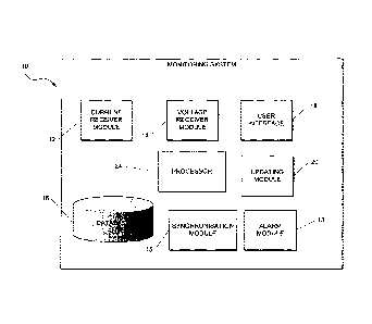
Referring to Figure 1 of the drawings, a system for determining condition
monitoring information of a rotating machine based on shaft signals is
generally indicated by reference numeral 10. The system 10 provides for
both monitoring and recording of new data, and playback of existing
CA 02747702 2011-06-17
WO 2010/070465 PCT/1B2009/054040
-8-
historical data sets. In one example embodiment, the rotating machine
comprises a generator, or the like.
In a sample embodiment, the system 10 typically provides three levels of
trending:
a) High resolution data (typically 2 second intervals) maintained for 24
hours;
b) Medium resolution data (settable intervals ¨ typically 15 minutes) ¨
maintained indefinitely. In an example embodiment the system 10
can only handle about a year worth of data, anything older has to be
archived manually; and
c) Low resolution data (typically 24 hour intervals).
Data for the three trending levels is stored in three corresponding data files
in a database (described below).
The system 10 typically comprises a plurality of components or modules
which correspond to the functional tasks to be performed by the system 10.
In this regard, "module" in the context of the specification will be
understood
to include an identifiable portion of code, computational or executable
instructions, data, or computational object to achieve a particular function,
operation, processing, or procedure. It follows that a module need not be
implemented in software; a module may be implemented in software,
hardware, or a combination of software and hardware. Further, the
modules need not necessarily be consolidated into one device but may be
spread across a plurality of devices. In particular, the system 10 includes a
current receiver module 12, a voltage receiver module 14, a
synchronisation module 15, an alarm module 13, a user interface 18, an
updating module 20, and a database 16.
The current receiver module 12 is arranged to receive current signals from
a current brush associated with the machine shaft (not shown) whereas the
CA 02747702 2011-06-17
WO 2010/070465 PCT/IB2009/054040
-9-
voltage receiver module 14 is arranged to receive voltage signals from a
voltage brush associated with the machine shaft.
The system 10 preferably Includes a processor 24 for determining, from the
received voltage and current signals, voltage and current data relating to
the machine. The processor 24 is typically arranged to determine a DC
average voltage and RMS voltage for the received voltage signal.
The processor 24 is also arranged to analyse harmonic content of the
received voltage signal. The processor 24 is arranged to apply or obtain a
Fast Fourier Transform (FFT) of the voltage signal. It follows that the
processor 24 is therefore arranged to generate a FFT display and a
harmonic trend of the voltage signal, a frequency domain representation of
voltage signal harmonics, and a short-term trends representation
comprising the more important harmonic components and the
instantaneous value display of these harmonics. It will be understood that
this data, in addition to the DC and RMS voltage, typically forms part of the
voltage data. It will be noted that the FFT display is typically the
corresponding harmonics or spectrum of the voltage signal.
The voltage signal is processed to a frequency of at least 1.50kHz.
However the upper limit can be higher than 1.50kHz.
The processor 24 is further arranged to determine the DC average current
and RMS current or RMS average current for the received current signal.
The processor 24 is further arranged to generate or update a scatter plot
(explained in greater detail below). The scatter plot is typically a phase
resolved scatter plot. In this regard, it will be noted that the scatter plot
represents the phase resolved peak values of pulse events that are present
on the shaft. In addition to the determined DC and RMS average current,
the current data may comprise the scatter plots or information associated
therewith.
CA 02747702 2011-06-17
WO 2010/070465 PCT/IB2009/054040
-10-
The system 10 is arranged such that the synchronisation module 15
provides the processor 24 with adequate information to allow the voltage
and current data to be properly phase resolved, and the scatter plot to be
correctly assembled.
To interrogate voltage and current signals received from the shaft, the
processor 24 is advantageously arranged to perform low frequency pulse
recognition in the time domain. An example illustration of a low frequency
pattern is the time domain is shown in Figure 3. The processor 24 is
arranged to analyse the pattern in the time domain and identify or
determine at least the peak to trough ratio, the peak to average ratio, the
frequency of the peaks, and the rise and fall times of the peaks.
In an example embodiment, the processor 24 is also arranged to perform
low frequency harmonic analysis on the received voltage and/or current
signals. An illustration of a typical low frequency harmonic signal is shown
in Figure 4. Low Frequency Harmonic Analysis is advantageously used to
localise individual faults by identifying a harmonic pattern associated with
that particular fault. It will be appreciated that patterns of faults are
stored
in the database 16 as will be discussed below.
In an example embodiment, the processor 24 is also arranged to use high
frequency spectral analysis to determine problems associated with the
generator. In particular, the processor 24 is arranged to use EMI
(Electromagnetic Interference) testing to determine problems associated
with the generator. An illustration of a typical high frequency spectral
analysis pattern is shown in Figure 5.
The processor 24 may further be arranged to use high frequency pattern
recognition versus the energizing half waveforms to at least identify faults
in
the generator. The processor 24 may therefore make use of phase
resolved patterns in order to do this. The processor 24 requires the output
of the synchronisation module 15 to achieve this. An illustration of a typical
CA 02747702 2011-06-17
WO 2010(070465 PCT/IB2009/054040
-11-
high frequency pattern versus the energizing half waveforms is shown in
Figure 6.
It will be noted that the database 16 is arranged to store the determined
voltage and current data thereby to trend at least the determined voltage
data to at least determine voltage data trends associated with the
generator. These trends are typically stored in trends records in the
database 16. It will be noted that the DC and RMS current are also trended
in the database 16.
An acquisition unit, in the current receiver module 12, is arranged to
process the pulses from the current brush. The acquisition unit has a
frequency response from 150 kHz to 250 MHz.
The user interface 18 typically includes a GUI displayable to a user by way
of a monitor of a personal computer, laptop, PDA, or the like. The user
interface 18 is therefore arranged to receive data from a user and also to
present at least some of the determined voltage and current data to the
user. It follows that the user interface 18 is therefore arranged to display
voltage and/or current data to the user in the form of numeric displays of
the actual shaft voltage and current signals, raw shaft voltage and current
waveforms, harmonic content information associated with the voltage
signals received from the voltage brush, scatter plot displays of the current
signals received from the current brush, and alarm events and associated
fault diagnostic information (discussed below). It will be appreciated that
most of the information or data pertaining to the generator, which is
displayed by the user interface 18, is generated by the processor 24.
The system 10 includes a data updating module 20 arranged to update
data in the database 16. This data may be current and voltage data, trend
data or records, or any data hereinbefore mentioned. It will be noted
however, that trend data may be interpreted from previous voltage and
current data. In an example embodiment, the data updating module 20 is
arranged to update particular configuration files stored in the database.
CA 02747702 2011-06-17
WO 2010/070465 PCT/I132009/054040
-12-
In an example embodiment the user interface 18 is arranged to prompt a
user for information indicative of the generator thereby to identify the
generator. The user Interface 18 may therefore be arranged to prompt the
user for information which includes the generator or power station name,
unit number, earthing configuration, or the like.
The system 10 is arranged to search the database 16 for any existing
historical voltage and/or current data trends relating to the identified
generator being monitored. The system 10 is conveniently arranged to
retrieve any located historical trends from the database 16 and present the
same to the user via the user interface 18. In certain example
embodiments, the user interface 18 presents information to the user in a
read-only format.
The system 10 is arranged to obtain a timestamp for the latest capture.
Depending on the input, the processor 24 may be arranged to apply
appropriate amplitude scaling factors to compenste for transducer factors to
at least the received voltage signal. A corresponding voltage time domain
waveform may then be presented to the user via the user interface 18.
For ease of explanation, in an example embodiment the values (for a 50 Hz
machine) which are trended (and stored in the database 16) by the
processor 24 are:
= Current brush RMS
= Current Brush DC
= Voltage brush RMS
= Voltage brush DC
= Voltage brush 25Hz
= Voltage brush 50Hz
= Voltage brush 100Hz
= Voltage brush 150Hz
= Voltage brush 200Hz
CA 02747702 2011-06-17
WO 2010/070465 PCT/IB2009/054040
-13-
= Voltage brush 250Hz
= Voltage brush 300Hz
= Voltage brush 350Hz
= Voltage brush 400Hz
= Voltage brush 450Hz
= Voltage brush 500Hz
= Voltage brush 550Hz
= Voltage brush 600Hz
= Voltage brush 650Hz
= Voltage brush 700Hz
= Voltage brush 750Hz
= Voltage brush 800Hz
= Voltage brush 850Hz
= Voltage brush 900Hz
= Voltage brush 950Hz
= Voltage brush 1000Hz
It will be noted that for a machine operating at a frequency of other than 50
Hz, these values are scaled accordingly.
Current brush and voltage brush as listed above relate to the current and
voltage signals received from the current and voltage brushes respectively.
As previously mentioned, the processor 24 is arranged to analyse the
current signal which is typically a time domain waveform or signal. The
processor 24 is then arranged to apply scaling to the current signal to
compensate for transducer factors, and generate and display a
corresponding scatter plot to the user via the user interface 18. The
updating module 20 is arranged to update a record of scatter plots in the
database 16.
It will be appreciated that each scatter plot is a graphical display of time
domain results collected and superimposed over a period of time. The
scatter plots are three-dimensional ¨ the horizontal axis represents a 20
CA 02747702 2011-06-17
WO 2010/070465 PCT/FB2009/054040
-14-
millisecond mains-waveform period. The vertical axis represents signal
amplitude. The image intensity axis represents counts of similar events.
Typically, a scatter plot consists of a number of dots, representing
amplitude levels of time domain waveforms. The colour of each dot
represents the number of such occurrences.
Each time domain capture that is acquired by the system 10 is analysed by
the processor 24, and referenced to the synchronisation module 15, to
produce an interim scatter plot, having for example 1 bit intensity
resolution.
A number (typically 240) of these interim scatter plots are then combined to
produce the final scatter plot that is displayed by the user interface 18.
This
final plot has 8 bit intensity resolution. The interim scatter plots are
stored
in local memory on a first in first out (FIFO) basis, so that the final
scatter
plot always contains the latest results.
Each time domain current brush waveform that is acquired by the system
is processed by the processor 24 as follows to produce an interim
scatter plot. The first number of milliseconds displayed in this waveform
corresponds to the duration of one energising waveform cycle extracted.
This data has a higher horizontal resolution than is available on the scatter
plot. Thus several points on the time domain waveform is represented with
a single 'time slice' of the scatter plot.
If one considers one time slice of a scatter plot and the corresponding
subset of points in the time domain capture that map to it, the time slice of
the scatter plot contains a number of vertical divisions. For each of these
divisions, a value of 0 is assigned by the processor 24 if the time domain
waveform subset has no points at that amplitude, and a value of 1 if the
time domain waveform subset has one or more points at that amplitude.
This is repeated for each time slice of the interim scatter plot. The result
is
a scatter plot representing only one time domain capture. At each location,
the interim scatter plot has a minimum value of 0, and a maximum value of
1.
CA 02747702 2011-06-17
WO 2010/070465 PCT/IB2009/054040
-15-
In a sample embodiment, the system 10 monitors if the date of data capture
or reception has changed, and if so, creates a new file structure for logging
data in the database 16. This is typically done every 24 hours to keep
fileset sizes manageable. It follows that the processor 24 is arranged to
manage the size of high resolution trends records in the database 16.
The updating module 20 is arranged to append latest DC, RMS and voltage
brush harmonic values to the high resolution trends file.
It will be noted that each time an entry is made to the medium resolution
trends data file, a full set of data (voltage brush time domain and harmonic
traces, plus current brush scatter) is recorded in the database 16.
Such a logging event can occur for example when:
a) The prescribed logging interval for medium resolution data has been
reached.
b) A reportable fault has occurred, as outlined below.
If the date of data capture follows into the next day, the processor 24
computes delta values for RMS, DC and voltage brush harmonic values.
The alarm module 13 is typically arranged to determine from the voltage
and current information if a fault condition has occurred, the alarm module
13 being further arranged to generate an alarm signal or condition in
response a fault occurring. In an example embodiment, the alarm module
13 is arranged to compare levels of RMS, DC and voltage brush harmonics
against corresponding alarm levels or thresholds stored in, for example an
alarms configuration file in the database 16. It will be noted that recent
alarm events, together with suggestions of possible causes of the alarms
are displayed to the user via the user interface 18.
CA 02747702 2011-06-17
WO 2010/070465
PCT/IB2009/054040
-16-
In a preferred example embodiment, the alarms configurations file is in the
form of or includes a look-up table of known fault conditions that are
defined in term of their harmonic content in order to determine if a
particular
condition is a fault condition. The alarm module 13 optionally makes use of
harmonic pattern recognition with patterns stored in the look-up table to
recognise faults.
New fault conditions can be advantageously stored in the fault table in the
database 16. If applicable, the processor 24 also compares delta values
with corresponding alarm levels or thresholds.
= The alarms configuration file or the look-up table contains 'orange' and
'red'
threshold levels for each key value (typically at least certain elements of
the
determined voltage and current data) to be compared. Each key value is
compared to these and rated as green, orange or red for example. Key
values that are orange or red are grouped together to form a list. This list
is
compared against known fault definitions lists stored in the database 16. If
the present list matches any fault definitions lists or entries therein, a
list of
possible causes for the fault is retrieved from the database 16 and is
present to the user. If it is not contained in the database 16, a result of
'unknown fault' is returned to the user.
A preferred example embodiment features a refinement that each time a
fault occurs, a record is kept of the number of occurrences of that fault. If
it
is a new fault, it is reported to or flagged for the user. The second time the
same fault occurs, it is only reported if a defined hold-off time has elapsed
since the last occurrence. Each time the same fault occurs, the hold-off
time for that fault is dynamically adjusted. Thus duplicate faults occurring
in
a short space of time are not reported. If a particular fault is persistent,
its
holdoff-time grows to a limit of 24 hours. Should that fault then desist, its
holdoff-time is progressively reduced back to the default.
When a reported alarm occurs, it is entered into the alarms log file by the
updating module 20, and an entry is made in the main medium resolution
CA 02747702 2011-06-17
WO 2010/070465 PCT/1B2009/054040
-17-
trends file. A full set of data (voltage brush time domain and harmonic
traces, plus current brush scatter) is also recorded in the database 16. This
constitutes an additional entry into the data logs over and above the
regular, set interval logging.
If an alarm which is due to be logged has occurred, or a scheduled logging
interval has been reached, the updating module 20 is arranged to store, in
the database 16, the latest data which includes the latest scatter plot,
voltage brush time domain waveform and spectrum.
A number of faults may be identifiable based on the harmonic pattern
recognition as hereinbefore mentioned. For a generator, these faults may
be for example sagging of the rotor, rotor magnetic asymmetry, problems
with rotor protection equipment, problems within the magnetic circuit of the
stator, any large spark from within the machine, the use of segmental
punching, joints in the stator laminations, rotor eccentricities, split stator
cores, split rotor cores, stator sagging, the use of stator segments of
different permeability, un-symmetrical stacking of the core, unevenly
spaced axial cooling ducts, steam problems in the turbine, sparking from
the bearings, stray flux imbalances, rotor earth faults, exciter problems, or
the like.
The system 10 may be arranged to allow either the live capture and display
of present data, or the playback and display of previously captured data.
The invention will now be described, in use, with reference to Figure 2. A
flow diagram of the example method shown in Figure 2 is described with
reference to Figure 1, although it is to be appreciated that the example
methods may be applicable to other systems (not illustrated) as well.
In Figure 2 the flow diagram of a method in accordance with an example
embodiment is generally indicated by reference numeral 30.
CA 02747702 2011-06-17
WO 2010/070465 PCT/1B2009/054040
-18-
The method 30 includes receiving, at block 32, voltage signals from the
voltage brush associated with the shaft by way of the voltage receiver
module 14.
Similarly, the method 30 includes receiving, at block 34, current signals
from the current brush associated with the shaft by way of the current
receiver module 12. It will be appreciated that the method steps at blocks
32 and 34 may occur simultaneously or in parallel.
Once the voltage and current signals are received, the method 30 includes
determining, at block 36 by way of the processor 24, from the received
voltage and current signals, voltage and current data relating to the
generator being monitored as hereinbefore described. It follows that
method 30 also includes referencing this data to the output of the
synchronisation module 15. This may include receiving a synchronisation
signal to allow the received voltage and current data to be synchronised
with an energising waveform.
The method 30 also includes determining the DC and RMS voltage and
current as hereinbefore described. The method 30 also includes
performing a FFT on the voltage signal, and generating or processing a
scatter plot for the current signal as hereinbefore described.
The method 30 then includes presenting, at block 38, at least some of the
determined voltage and current data to a user via the user interface 18. It
will be noted that a user is able to assess the condition of the machine
(generator) from the information which the system 10 presents to them.
The method 30 also includes trending, at block 40, at least the determined
voltage data to at least determine voltage data trends associated with the
machine. The method 30 typically includes trending both the determined
voltage and current data in the database 16. The user may optionally
retrieve tending information or data from the database 16 via the user
interface 18.
CA 02747702 2011-06-17
WO 2010/070465 PCT/1132009/054040
-19-
In a preferred example embodiment, the method 30 includes determining,
at block 42, from the voltage and current data if a fault condition has
occurred and generating an alarm signal or condition in response thereto
as hereinbefore described by way of the alarm module 13. In an example
embodiment the method 30 therefore includes comparing levels of RMS,
DC and voltage brush harmonics against corresponding alarm levels or
thresholds stored in the database 16. If applicable, the method 30 includes
comparing delta values with corresponding alarm levels or thresholds. If an
alarm has occurred, or a scheduled logging interval has been reached, the
method includes storing, in the database 16, the latest determined current
and voltage data which includes inter alia voltage brush time domain and
harmonic traces, plus current brush scatter, plus an entry in the medium
resolution trends file.
In an example embodiment when in playback mode the method includes
prompting the user by way of the user interface 18 for information indicative
of the generator in a similar fashion as hereinbefore described for the
logging mode.
The method includes searching the database 16 for any existing historical
trends similarly to the fashion as hereinbefore described. Also similarly to
the logging mode, the method includes retrieving any located historical
trends from the database 16 and presenting the same to the user via the
user interface 18.
The method includes presenting relevant configuration information in read-
only format to the user.
The method also includes presenting to the user, via the user interface 18,
the time domain voltage brush record matching a current playback point in
the fileset.
CA 02747702 2011-06-17
WO 2010/070465 PCTf182009/054040
-20-
The method may include presenting the voltage brush harmonic record
matching the current playback point in the fileset to the user.
The method may include presenting to the user the RMS and DC values of
the current and voltage from the point in the trends file matching the current
playback point in the fileset.
The method may include presenting the scatter plot matching the current
playback point in the fileset to the user. The method may also include
presenting to the user the most recent alarm events (from the alarms log
file) immediately preceding the current playback point in the fileset. At
least
some of the steps corresponding to the playback mode may be repeated at
predetermined or user selectable intervals.
The method may include displaying the raw time domain waveforms, which
were corrected for transducer factor scaling at the time of logging.
The method may include updating fields that display average and peak
values of both RMS and DC components of the current and voltage, plus a
summary of recent alarm events.
The method may include presenting to a user a display which typically has
the following components:
a) Time domain representation of voltage brush waveform.
b) Frequency domain representation of voltage signal harmonics.
c) Scatter plots of signals from the current brush.
d) Short-term trends window representing the more important
harmonic components.
e) Instantaneous value display of the quantities in d).
The invention as hereinbefore described provides a way more conveniently
to analyse rotating machines shaft signals thereby to provide condition
monitoring information of the rotating machine. The system as
CA 02747702 2011-06-17
WO 2010/070465 PCT/IB2009/054040
-21-
hereinbefore described is able to advantageously display a trend of
individual harmonics from the voltage brush.