Note : Les descriptions sont présentées dans la langue officielle dans laquelle elles ont été soumises.
CA 02747792 2013-08-05
SPECIFICATION
GROMMET
TECHNICAL FIELD
0001 The present invention relates to a grommet which is
mounted on a wire harness wired on a car and mounted on a
through-hole of a car body panel. More particularly the present
invention is intended to improve workability in mounting the
wire harness on the grommet.
BACKGROUND ART
0002 The wire harness is wired from an engine room of a car to
an interior side in penetration through a through-hole formed
through a dash panel (or cowl panel) partitioning the engine
room and the interior from each other. To prevent water and
dust from penetrating into the interior from the through-hole,
the wire harness is sheathed with the grommet made of rubber or
elastomer integrally molded, and a car body-locking concave part
formed on the grommet is locked to the peripheral edge of the
through-hole.
0003 As this kind of the grommet, the present applicant
proposed the grommet 100 shown in Fig. 9 as disclosed in
Japanese Patent Applications Laid-Open No. 2003-111250.
In the grommet 100, as shown in Fig. 9(A), the diameter-
1
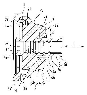
CA 02747792 2011-06-17
increased tubular part 102 where the car body-locking concave
part 103 is formed is continuous with the first small-diameter
tubular part 101. The closed wall part 104 is continuous with
the open end of the diameter-increased tubular part 102 disposed
at the large-diameter side thereof. The second small-diameter
tubular part 105 is projected from the center of the closed wall
part 104. As shown in Fig. 9(B), the adhesive tape T is wound
around wire harness W/H at the front end of the first small-
diameter tubular part 101 disposed at one end of the grommet 100
in its longitudinal direction and the rear end of the second
small-diameter tubular part 105 disposed at the other end
thereof in its longitudinal direction to fix the wire harness to
the grommet 100.
The diameter-increased tubular part 102 is provided with
the wire insertion part 106 composed of the through-hole 106a
through which the wire consisting of the washer hose and the
hood opener cable is inserted and the wire insertion tubular
portion 106b inserted through the hollow portion of the
diameter-increased tubular part 102 from the peripheral edge of
the through-hole 106a and projected from the closed wall part
104. The wire insertion tubular portion 106b projected from the
closed wall part 104 is positioned on the periphery of the
second small-diameter tubular part 105.
0004 As described above, the wire insertion tubular portion
106b is projected from the closed wall part 104 and positioned
2
CA 02747792 2011-06-17
,
on the periphery of the second small-diameter tubular part 105.
Thus in winding the adhesive tape T around the periphery of the
group of electric wires of the wire harness W/H at the front end
of the second small-diameter tubular part 105, the wire
insertion tubular portion 106b positioned on the periphery of
the second small-diameter tubular part 105 obstructs a tape-
winding work, thus posing a problem that it is difficult to
perform the tape-winding work. In addition, because it is
necessary to wind the tape around the wire harness W/H at the
front end of the first small-diameter tubular part 101 disposed
at one end of the grommet 100 in its longitudinal direction and
the rear end of the second small-diameter tubular part 105
disposed at the other end thereof in its longitudinal direction.
Thus it is necessary to perform the work of fixing the grommet
100 and the wire harness W/H to each other at many processes.
Further when the closed wall part 104 is formed at the end of
the large-diameter side of the diameter-increased tubular part,
a slit is diametrically formed through the closed wall part 104
to remove the core loaded in the hollow portion of the diameter-
increased tubular part 102 in forming the grommet 100 with a
molding die. The core removal work is not easy.
0005 But when the tape is wound around wire harness W/H at only
one portion, namely, the front end of the first small-diameter
tubular part 101 continuous with the end of the diameter-
increased tubular part 102 at its small-diameter side to fix the
3
CA 02747792 2011-06-17
wire harness W/H and the grommet 100 to each other, the force of
retaining the configuration of the diameter-increased tubular
part 102 at its large-diameter side decreases. Thereby the car
body-locking concave part 103 disposed on the large-diameter
side peripheral surface of the diameter-increased tubular part
102 to be locked to the through-hole of the car body panel is
liable to deform, which poses a problem that the reliability of
the waterproof function deteriorates.
PRIOR ART DOCUMENT
PATENT DOCUMENT
0006 Patent document 1: Japanese Patent Applications Laid-Open
No. 2003-111250
SUMMARY OF THE INVENTION
PROBLEM TO BE SOLVED BY THE INVENTION
0007 The present invention has been made in view of the above-
described problem. It is an object of the present invention to
enhance the reliability of a waterproof function by setting a
portion of the grommet where a tape is wound around a wire
harness to only a front side of a small-diameter tubular part
projected from an end of a diameter-increased tubular part at a
small-diameter side thereof, not forming a second small-diameter
tubular part where it is difficult to wind the tape, and
enhancing the force of retaining a large-diameter side of the
4
CA 02747792 2011-06-17
diameter-increased tubular part on which a car body-locking
concave part to be locked to a through-hole of a car body panel
is formed.
MEANS FOR SOLVING THE PROBLEM
0008 To solve the above-described problem, the present
invention provides a grommet, made of rubber or elastomer, which
is locked to a through-hole of a car body panel with the grommet
sheathing a wire harness for a car, having:
a small-diameter tubular part through which the wire
harness composed of a group of electric wires is inserted with
the wire harness in close contact therewith to fix the wire
harness to the grommet at only a front end of one side portion
of the small-diameter tubular part with a tape wound around the
wire harness;
a diameter-increased tubular part which is continuous with
a periphery of a middle portion of the small-diameter tubular
part in a longitudinal direction thereof and increases in the
diameter thereof with the diameter-increased tubular part
surrounding other side portion of the small-diameter tubular
part;
a car body-locking concave part annularly formed on a
peripheral surface of the diameter-increased tubular part at a
large-diameter side thereof;
inner ribs, provided at intervals in a circumferential
CA 02747792 2011-06-17
. direction of the grommet, which connect an inner peripheral
surface of the diameter-increased tubular part and a peripheral
surface of the other side portion of the small-diameter tubular
part to each other; and
a wire insertion tubular part which is continuous with a
through-hole for a wire formed through the diameter-increased
tubular part and projects from a large-diameter side open end in
penetration through the diameter-increased tubular part,
wherein the inner rib is projectingly formed by separating
the inner rib from the inner peripheral surface of the diameter-
increased tubular part in a region from a position at which the
diameter-increased tubular part contacts an inner peripheral
surface of the through-hole of the car body panel to a position
at which the diameter-increased tubular part confronts the car
body-locking concave part by forming a gap between the inner rib
and the inner peripheral surface of the diameter-increased
tubular part; a front-end portion of the other side portion of
the small-diameter tubular part is projected from a front end of
the inner rib; and the front-end portion of the small-diameter
tubular part is disposed at the large-diameter side open end of
the diameter-increased tubular part; and
at a position confronting a front-end surface of said
inner rib with a gap formed between said front-end surface of
said inner rib and said position, an annular interference wall
is projected from a large-diameter side inner peripheral surface
of said diameter-increased tubular part.
6
CA 02747792 2011-06-17
0009 As described above, in the grommet of the present
invention, the adhesive tape is wound around the group of the
electric wires of the wire harness at only the front end of the
one side portion of the small-diameter tubular part which Ls
6a
CA 02747792 2011-06-17
continuous with the end of the diameter-increased tubular part
at its small-diameter side and projected outward to fix the wire
harness to the grommet. Further the tape is not wound at the
side where the wire insertion tubular part consisting of a
washer hose or/and a hood opener cable projects. Thus the
number of tape-winding portions is one. Therefore it is
possible to decrease the number of tape-winding works. Further
because the tape-winding work is eliminated at the side where
the wire insertion tubular part projects, the work of winding
the adhesive tape around the wire harness to fix the wire
harness to the grommet can be easily performed.
0010 The inner rib connecting the peripheral surface of the
other side portion of the small-diameter tubular part passing
through the inside of the diameter-increased tubular part and
the inner peripheral surface of the diameter-increased tubular
part with each other is extended to the neighborhood of the
small-diameter side open end. Therefore it is possible to
enhance the force for retaining the configuration of the
diameter-increased tubular part. Further because the front side
of the small-diameter tubular part which closely contacts the
wire harness is projected from the front end of the inner rib,
it is possible to enhance the force for retaining the
configuration of the diameter-increased tubular part, restrain
the deformation of the car body-locking concave part which is
fitted in the through-hole of the car body panel, and thus
7
CA 02747792 2011-06-17
enhance the reliability of the waterproof function.
0011 The inner rib is separated from the position at which the
diameter-increased tubular part contacts the inner peripheral
surface of the through-hole of the car body panel to the
position at which the diameter-increased tubular part confronts
the car body-locking concave part by forming the gap between the
inner rib and the inner peripheral surface of the diameter-
increased tubular part. Therefore in fitting the car body-
locking concave part of the grommet in the through-hole of the
car body panel, it is possible to smoothly inwardly deform the
diameter-increased tubular part and thus decrease the insertion
force.
0012 As described above, at a position confronting a front-end
surface of the inner rib with a gap formed between the front-end
surface of the inner rib and the position, an annular
interference wall is projected from a large-diameter side inner
peripheral surface of the diameter-increased tubular part.
The interference wall projected from the inner peripheral
surface of the diameter-increased tubular part at its large-
diameter side is set short in its radial direction to such an
extent that the interference wall and the front-end surface of
the inner rib disposed at the peripheral side thereof overlap on
each other. The projected other end portion of the small-
diameter tubular part is positioned at the center of the open
end surrounded with the interference wall.
8
CA 02747792 2011-06-17
By forming the interference wall at the position
confronting the inner rib, when the inner rib or a portion of
the car body-locking concave part disposed at the side the of
diameter-increased tubular part deforms, the inner rib and the
interference wall contact each other, thus restraining
deformation of the car body-locking concave part and enhancing
the force of retaining the configuration of the grommet.
Thereby it is possible to hold the waterproof performance.
0013 It is preferable that a plurality of projected stepped
parts is formed on a portion of the peripheral surface of the
diameter-increased tubular part confronting a position at which
the inner rib is formed by axially extending the projected
stepped parts from ends thereof continuous with the small-
diameter tubular part to a position at which the projected
stepped parts reach the car body-locking concave part; and
a mountain-shaped rib is projectingly formed on an outer
surface of each of the projected stepped parts in a region from
an end thereof connected with the small-diameter tubular part to
a contact position where the outer surface of each of the
projected stepped parts contacts a peripheral edge of the
through-hole of the car body panel when the grommet is inserted
into the through-hole; and a groove is axially formed between a
portion of the diameter-increased tubular part on which the
mountain-shaped rib is projectingly formed and the small-
diameter tubular part.
9
CA 02747792 2011-06-17
0014 As described above, by forming a plurality of the
projected stepped parts axially extended from the small-diameter
tubular part to the car body-locking concave part on the
peripheral surface of the diameter-increased tubular part by
circumferentially spacing them at certain intervals, the area of
contact between the inner peripheral surface of the through-hole
of the car body panel and the peripheral surface of the
projected stepped part is decreased. Thus it is possible to
decrease the insertion force required to mount the grommet on
the through-hole.
0015 As described above, it is preferable that the mountain-
shaped rib is projectingly formed on the outer surface of each
of the projected stepped parts in the region from the end
thereof connected with the small-diameter tubular part to the
contact position where the outer surface of each of the
projected stepped parts contacts the peripheral edge of the
through-hole of the car body panel when the grommet is inserted
into the through-hole.
The mountain-shaped rib has a configuration which is
projected in a direction orthogonal to an axial direction of the
grommet from the end of the projected stepped part continuous
with the small-diameter tubular part and has an inclined surface
inclined from a projected end of a summit of the mountain-shaped
rib toward the outer surface of the projected stepped part.
with the small-diameter tubular part being inserted into
CA 02747792 2011-06-17
the through-hole of the car body panel and with the inclined
surface of a portion of the mountain-shaped rib disposed at the
lower side of the grommet being held on the inner peripheral
surface of the through-hole, the grommet can be temporarily
placed on the inner peripheral surface of the through-hole till
the small-diameter tubular part is pulled into the through-hole
from the other side thereof. Further with the lower side of the
grommet being temporarily placed on the inner peripheral surface
of the through-hole, the peripheral edge of the through-hole is
brought into contact with a position of the upper side of the
grommet not beyond the car body-locking concave part.
0016 As described above, by forming a plurality of the
projected stepped parts on the peripheral surface of the
diameter-increased tubular part at certain intervals in the
circumferential direction of the grommet and forming the
mountain-shaped rib projectingly at the side of each projected
stepped part connected with the small-diameter tubular part,
even though the grommet is inclined by its dead weight during a
period of time from a time when an operator inserts the small-
diameter tubular part into the through-hole of the car body
panel at one side thereof (for example, engine room side) till
the operator performs a pulling work after moving to the other
side (for example, interior side) of the through-hole, the
inclined surface of a portion of the mountain-shaped rib
disposed at the lower side of the grommet is caught by a lower-
11
CA 02747792 2011-06-17
side inner peripheral surface of the through-hole. Thus it is
possible to hold the grommet in a temporary state. That is, the
mountain-shaped rib can be used to hold the grommet in a
temporary state.
In performing the pulling work by gripping the small-
diameter tubular part which has passed through the through-hole
to hold the grommet in a state where at the upper side of the
grommet opposed to the lower side thereof, the car body-locking
part does not pass through the through-hole with the lower side
of the grommet being held in the temporary state, it is possible
to prevent the occurrence of a situation in which the car body-
locking concave part disposed at the upper side of the grommet
does not fit in the through-hole.
0017 In addition, the mountain-shaped rib which easily
interferes with the peripheral edge of the through-hole is
disposed on a portion of the projected stepped part at the side
of the small-diameter tubular part. Thus when the grommet is
obliquely inserted into the through-hole of the car body panel
from the small-diameter tubular part and thus the summit of the
mountain-shaped rib interferes with the peripheral edge of the
through-hole, the portion of the mountain-shaped rib which has
interfered with the peripheral edge of the through-hole cannot
be inserted into the through-hole when the grommet is pulled at
the other side of the through-hole. Thus the operator is
incapable of inserting the grommet into the through-hole.
12
CA 02747792 2011-06-17
Thereby the operator finds that the grommet has been pulled in
an oblique posture and is obliged to make the grommet straight
to prevent the mountain-shaped rib from interfering with the
peripheral edge of the through-hole. In this manner it is
possible to securely prevent the grommet from being obliquely
inserted into the through-hole.
0018 As described above, it is preferable to form the groove
between the mountain-shaped rib and the peripheral surface of
the small-diameter tubular part.
As described above, the mountain-shaped rib is projected
from the end of the projected stepped part at the side of the
small-diameter tubular part. Because the groove is formed
between the mountain-shaped rib and the peripheral surface of
the small-diameter tubular part, bending of the small-diameter
tubular part is not restricted. When it is necessary to
suddenly bend the small-diameter tubular part, the small-
diameter tubular part can be easily bent without pulling the
diameter-increased tubular part.
0019 It is preferable to form six to eight projected stepped
parts on the peripheral surface of the diameter-increased
tubular part and six to eight inner ribs on the inner peripheral
surface of the diameter-inCreased tubular part confronting the
projected stepped parts. The projected stepped parts and the
inner ribs have an equal circumferential width and are extended
axially.
13
CA 02747792 2011-06-17
Because as described above, the projected stepped parts
and the inner ribs have an equal circumferential width and are
extended axially, the projected stepped parts are extended
radially with the ends of the adjacent projected stepped parts
at the side of the small-diameter tubular part in proximity to
each other to form a triangular dent portion consisting of the
peripheral surface of the diameter-increased tubular part
between the adjacent projected stepped parts (between adjacent
inner ribs).
As described above, because the area of the thin dent
portion becomes larger toward the car body-locking concave part,
the grommet becomes increasingly flexible toward a radius
decrease direction, and the grommet insertion force can be
decreased.
As described above, by forming a large number of projected
stepped parts, for example, six to eight projected stepped parts
and the mountain-shaped rib on each projected stepped part, in
inserting the grommet into the through-hole from the small-
diameter tubular part and temporarily placing the grommet on the
inner peripheral surface of the through-hole, it is possible to
stably hold the grommet in the temporary state because a large
number of the mountain-shaped ribs to be held by the inner
peripheral surface of the through-hole is formed with the
mountain-shaped ribs in contact therewith.
0020 The wire insertion tubular part is formed on the diameter-
14
CA 02747792 2011-06-17
increased tubular part at the thin dent portion thereof where
the projected stepped parts and the inner ribs are not formed.
EFFECT OF THE INVENTION
0021 As described above, because the portion of the grommet
where the tape is wound around the wire harness to fix the wire
harness to the grommet is set to the front end of the one side
portion of the small-diameter tubular part projected from the
end of the diameter-increased tubular part at its small-diameter
side, it is possible to decrease the number of processes at
which the tape-winding work is performed. Further because the
wire insertion tubular part is not disposed at the portion of
the grommet where the tape is wound, and there is no portion
which obstructs the tape-winding work, it is possible to easily
perform the tape-winding work.
0022 In addition, the other side portion of the small-diameter
tubular part extended along the axis of the diameter-increased
tubular part is continuous with the inner peripheral surface of
the diameter-increased tubular part via the inner rib. Further
the inner rib is extended to the neighborhood of the large-
diameter side open portion of the diameter-increased tubular
part. Thereby it is possible to enhance the force for retaining
the configuration of the diameter-increased tubular part at its
large-diameter side and restrain the deformation of the car
body-locking concave part which is fitted in the through-hole of
CA 02747792 2011-06-17
the car body panel and hence enhance the waterproof performance.
Furthermore the inner rib is projectingly formed by
separating the inner rib from the inner peripheral surface of
the diameter-increased tubular part in the region from the
position at which the diameter-increased tubular part contacts
the inner peripheral surface of the through-hole to the position
at which the diameter-increased tubular part confronts the car
body-locking concave part by forming the gap between the inner
rib and the inner peripheral surface of the diameter-increased
tubular part. Therefore it is possible to decrease the grommet
insertion force in fitting the car body-locking concave part in
the through-hole of the car body panel.
BRIEF DESCRIPTION OF THE DRAWINGS
Fig. 1 is a perspective view of a grommet of an embodiment
of the present invention.
Fig. 2 is a sectional view of the grommet in an axial
direction thereof.
Fig. 3 is a sectional view of the grommet in a direction
perpendicular to the axial direction thereof.
Fig. 4 is a sectional view in which Fig. 2 is partly
enlarged.
Fig. 5 is a sectional view in which Fig. 2 is partly
enlarged.
Figs. 6(A) and 6(B) show a state in which a wire harness
16
CA 02747792 2011-06-17
is inserted through the grommet and fixed thereto and the
grommet is inserted through a car body panel.
Fig. 7 is an explanatory view of a temporary state from a
time when a grommet insertion work finishes until before a
pulling work starts.
Fig. 8 is an explanatory view in which a load is applied
to the grommet.
Fig. 9 shows a conventional grommet.
BEST MODE FOR CARRYING OUT THE INVENTION
0024 An embodiment of the present invention is described below
with reference to Fig. 1 through Fig. 8.
Similarly to the conventional grommet shown in Fig. 9, a
grommet 1 of this embodiment is fixed in advance to a wire
harness W/H wired to an interior side (Y) from an engine room
side (X) through a through-hole H of a dash panel P.
0025 The grommet 1 is made of rubber integrally molded.
The grommet 1 has a small-diameter tubular part 2 through
which the wire harness W/H composed of a group of electric wires
is inserted with the wire harness W/H in close contact therewith
to fix the wire harness W/H to only a front end 2d of one side
portion 2a of the small-diameter tubular part 2 with a tape
wound around the wire harness;
a diameter-increased tubular part 3 which is continuous
with a periphery of a middle portion of the small-diameter
17
CA 02747792 2011-06-17
tubular part 2 in a longitudinal direction thereof and increases
in the diameter thereof with the diameter-increased tubular part
3 surrounding the other side portion 2b of the small-diameter
tubular part 2;
a car body-locking concave part 4 annularly formed on a
peripheral surface of the diameter-increased tubular part 3 at a
large-diameter side thereof;
inner ribs 5, provided at intervals in a circumferential
direction of the grommet 1, which connect an inner periphery of
the diameter-increased tubular part 3 and a peripheral surface
of the other side portion 2b of the small-diameter tubular part
2 to each other;
projected stepped parts 6 formed on a peripheral surface
of the diameter-increased tubular part 3 at positions thereof
where the projected stepped parts 6 confront the inner ribs 5
respectively; and
a pair of wire insertion tubular parts 7 which is
continuous with through-holes 7a for a wire respectively formed
through a portion of the diameter-increased tubular part 3 where
the projected stepped parts 6 and the inner ribs 5 are not
formed and projects from a large-diameter side opening 3a in
penetration through an inside of the diameter-increased tubular
part 3.
0026 In the small-diameter tubular part 2, a front side of the
one side portion 2a projected from a small-diameter side of the
18
CA 02747792 2011-06-17
,
diameter-increased tubular part 3 is cut in half. Ribs 2d and
2e are circumferentially formed at a distal end of the front
side of the one side portion 2a and a proximal end of the front
side thereof respectively. A region between the ribs 2d and 2e
is set as a tape-winding portion.
Ribs 2f are axially formed at certain intervals on an
inner peripheral surface of the other side portion 2b extended
inside the diameter-increased tubular part 3 to enhance adhesion
between the small-diameter tubular part 2 and the wire harness
W/H inserted into the small-diameter tubular part 2.
0027 A side wall of the car body-locking concave part 4 is
composed of a first wall 4a disposed at the side of a front-end
thick portion 3b and a second wall 4c, disposed at the side of
the diameter-increased tubular part 3, which is opposed to the
first wall 4a with the first wall 4a and the second wall 4c
sandwiching a groove 4b therebetween. The projection amount of
the first wall 4a with respect to a bottom surface of the groove
4b is large, whereas that of the second wall 4c is small. That
is, the height of the first wall 4a and that of the second wall
4c are varied from each other. A lip 4e for pressure welding
use is formed on the bottom surface of the groove 4b.
0028 The projected stepped parts 6 formed on the peripheral
surface of the diameter-increased tubular part 3 are axially
extended at certain intervals in the circumferential direction
of the grommet 1 from a small-diameter side thereof continuous
19
CA 02747792 2011-06-17
with the small-diameter tubular part 2 to the front end of the
second wall 4c of the car body-locking concave part 4. The
projected stepped parts 6 are projected thickly and stepwise
from the peripheral surface of the diameter-increased tubular
part 3.
In this embodiment, eight projected stepped parts 6 are
formed. The projected stepped parts 6 have an identical
configuration. Widths W of the projected stepped parts 6 in the
circumferential direction thereof are equal to each other. Each
of the projected stepped parts 6 is radially formed on the
peripheral surface of the diameter-increased tubular part 3 with
each projected stepped part 6 being axially extended from a
connection end P1 at which the small-diameter tubular part 2 and
each of the projected stepped parts 6 are connected to each
other to a front-end point P4 of the second wall 4c.
0029 A mountain-shaped rib 9 is projectingly formed on an outer
surface 6a of each projected stepped part 6 in a region from the
connection end P1 at which the small-diameter tubular part 2 and
each of the projected stepped parts 6 are connected to each
other to a contact position P3 where the outer surface 6a of
each of the projected stepped parts contacts an inner peripheral
surface Ha of the through-hole H of the car body panel P when
the grommet 1 is inserted into the through-hole H. The
mountain-shaped rib 9 has a flat projected surface 9a projected
from the connection end P1 in a direction Z orthogonal to an
CA 02747792 2011-06-17
axis L of the grommet 1 and an inclined surface 9c inclined from
a summit 9b disposed at the front end of the flat projected
surface 9a toward the outer surface 6a of each of the projected
stepped parts 6. The inclined surface 9c serves as a temporary
placing surface to be used in a period of time between a time
when the grommet 1 is inserted into the through-hole H from one
side thereof and a time when the grommet 1 is pulled from the
other side of the through-hole H.
A groove 11 is formed by axially extending the groove 11
from the connection end P1 at which the small-diameter tubular
part 2 and each of the projected stepped parts 6 are connected
to each other between the small-diameter tubular part 2 and a
portion of the projected stepped part 6 having the mountain-
shaped rib 9 formed thereon. That is, the connection end P1 at
which the small-diameter tubular part 2 and each of the
projected stepped parts 6 are connected to each other is
disposed at the inner end of the groove 11.
0030 At a position where the inner rib 5 confronts the
mountain-shaped rib 9, a portion of the inner rib 5 formed in
confrontation with the projected stepped part 6 constitutes a
connection portion 5a connected with the inner peripheral
surface of the diameter-increased tubular part 3 and the
peripheral surface of the small-diameter tubular part 2. The
inner rib 5 is separated from the inner peripheral surface of
the diameter-increased tubular part 3 at the front side of the
21
CA 02747792 2011-06-17
inclined surface 9c of the mountain-shaped rib 9 and is
connected to only the peripheral surface of the small-diameter
tubular part 2, thus projecting toward the open side disposed at
the large-diameter side of the grommet 1 parallelly with the
axial direction L to form a separation portion 5b.
The separation portion 5b projects to the inner peripheral
side of the car body-locking concave part 4, thus forming a gap
Cl between the separation portion 5b and the inner peripheral
surface of the diameter-increased tubular part 3.
A projected end surface 5c of the separation portion 5b is
formed as a surface orthogonal to the axial line L. A front
portion 2c of the other side portion 2b of the small-diameter
tubular part 2 is projected from the center of the projected end
surface 5c.
0031 An annular interference wall 10 is projected from the
inner peripheral surface of the diameter-increased tubular part
3 by forming a gap 02 between the front side of the projected
end surface 5c of the inner rib 5 and the interference wall 10.
The projected amount of the interference wall 10 in its inner-
diameter direction is set small to such an extent that the
interference wall 10 and the peripheral side of the projected
end surface 5c overlap on each other.
A front portion of the small-diameter tubular part 2 is
positioned at the center of a large-diameter side opening 3a of
the diameter-increased tubular part 3 surrounded with the
22
CA 02747792 2011-06-17
annular interference wall 10. The wire insertion tubular part 7
is disposed on the peripheral side of the front portion of the
small-diameter tubular part 2 and projected outward.
0032 A thin dent portion 12 which widens triangularly toward
the large-diameter side of the grommet 1 is present between the
adjacent projected stepped parts 6 (between the adjacent inner
ribs 5 radially extended at the inner peripheral side of the
diameter-increased tubular part 3) radially extended at the
peripheral side of the diameter-increased tubular part 3. The
through-hole 7a for the wire is formed through each dent portion
12. The wire insertion tubular part 7 is projected from the
peripheral edge of the through-hole 7a for the wire. An axially
extended concave center groove 12a is formed at the center of
each dent portion 12 in its circumferential direction.
0033 In mounting the wire harness W/H on the grommet 1, the
small-diameter tubular part 2 is expanded with an expanding jig
(not shown) to insert the group of the electric wires of the
wire harness W/H thereinto. As shown in Fig. 6, after the group
of the electric wires is inserted into the small-diameter
tubular part 2, an adhesive tape 20 is wound around the front
portion of the one side portion 2a of the small-diameter tubular
part 2 projected outward from the small-diameter side of the
diameter-increased tubular part 3 and around the periphery of
the group of the electric wires pulled out of the front portion
of the one side portion 2a to fix the wire harness W/H and the
23
CA 02747792 2011-06-17
grommet 1 to each other with the adhesive tape 20. The winding
region where the adhesive tape 20 is wound is disposed between
the ribs 2d and 2e.
On the other hand, the adhesive tape 20 is not wound
around the front portion 2c of the other side portion 2b of the
small-diameter tubular part 2, but the front portion 2c of the
other side portion 2b thereof is brought into close contact with
the peripheral surface of the group of the electric wires.
A closed portion of the wire insertion tubular part 7
disposed at the front end thereof is cut to insert a washer hose
22 and a hood opener cable 23 through the wire insertion tubular
part 7.
0034 The method of mounting the grommet 1 attached to the wire
harness W/H on the through-hole H of the car body panel P
consisting of the dash panel partitioning the engine room side
(X) of the car and the indoor side (Y) thereof from each other
is described below.
0035 The small-diameter tubular part 2 is inserted into the
through-hole H from the engine room side (X). At this time, as
shown in Fig. 6(A), when the axial line L of the grommet 1 is
coincident with the axial line SO of the through-hole H and when
an inserted posture of the grommet 1 is straight, as shown in
Fig. 6(B), the mountain-shaped rib 9 does not interfere with the
peripheral edge of the through-hole H, but is capable of
entirely passing through the through-hole H.
24
CA 02747792 2011-06-17
0036 After an operator passes the one side portion 2a of the
small-diameter tubular part 2 and the mountain-shaped rib 9
through the through-hole H from the engine room side (X), the
operator moves to the interior side (Y) and grips the one side
portion 2a of the small-diameter tubular part 2 which has
penetrated through the through-hole H and projected into the
interior side (Y) and performs the work of pulling the grommet 1
into the interior side (Y).
During the period of time from a time when the operator
inserts the one side portion 2a of the small-diameter tubular
part 2 into the through-hole H until a time when the operator
moves to the interior side (Y) and pulls the small-diameter
tubular part 2, the grommet 1 is not held in the through-hole H
with the grommet 1 in close contact with the through-hole H.
This is because the grommet 1 has not been advanced to a contact
point of the projected stepped part 6 having a diameter equal to
an inner diameter of the through-hole H. Thus the grommet 1 is
left when the grommet 1 is midway in the insertion into the
predetermined position in the through-hole H with the grommet 1
being held by the wire harness W/H pulled out of both ends of
the grommet 1.
As shown in Fig. 6(B), even though the grommet 1 is
inserted straight into the through-hole H with the axial line L
of the grommet 1 being coincident with the axial line SO of the
through-hole H, the grommet 1 may incline by its own weight
CA 02747792 2011-06-17
because the peripheral surface of the grommet 1 is not held by
an inner peripheral surface Ha of the through-hole H of the car
body with the peripheral surface of the grommet 1 in close
contact with the inner peripheral surface Ha thereof.
0037 In this case, the grommet 1 is temporarily held with the
inclined surface 9c of the mountain-shaped rib 9 disposed on the
lower peripheral edge of the grommet 1 being placed on the inner
peripheral surface Ha of the through-hole H. Thus it is
possible to restrain the grommet 1 from inclining at a larger
angle. In the state in which the grommet 1 is temporarily held,
the upper peripheral edge of the grommet 1 is capable of keeping
the state in which the inner peripheral surface Ha of the
through-hole H is in contact with the portion of the projected
stepped part 6 disposed not beyond the car body-locking concave
part 4. That is, it is possible to prevent an upper-side
portion of car body-locking concave part 4 from passing through
the through-hole H and entering into the interior side (Y).
On the other hand, when the axial line L of the grommet 1
inclines greatly from the axial line SO of the through-hole H,
the flat projected surface 9a which is a part of the mountain-
shaped rib 9 interferes with the peripheral edge of the through-
hole H and is incapable of passing into the through-hole H.
Thus the grommet 1 cannot be inserted thereinto. Therefore to
prevent the flat projected surface 9a of the mountain-shaped rib
9 from interfering with the peripheral edge of the through-hole
26
CA 02747792 2011-06-17
H, the operator cannot help changing the insertion posture of
the grommet 1 from the oblique posture to the straight posture.
Thus it is possible to prevent the grommet 1 from being
obliquely inserted into the through-hole H.
0038 As described above, after the operator inserts the one
side portion 2a of the small-diameter tubular part 2 into the
through-hole H and moves to the interior side (Y) from the
engine room side (X) to perform the work of pulling the small-
diameter tubular part 2 by gripping the one side portion 2a
thereof which has projected into the interior side (Y), as shown
in Fig. 7, the operator performs the pulling work in the state
in which the inclined surface 9c of the mountain-shaped rib 9
disposed on the lower side of the grommet 1 is temporarily
placed on the inner peripheral surface Ha of the through-hole H.
The operator performs the pulling work in the state in
which the inclined surface 9c of the mountain-shaped rib 9
disposed on the lower side of the grommet 1 is temporarily
placed on the lower-side portion of the inner peripheral surface
Ha of the through-hole H. Because the inclined surface 9c is
continuous with the surface of projected stepped part 6 at the
diameter-increased side thereof disposed at the side of the car
body-locking concave part 4, the inner peripheral surface Ha of
the through-hole H sliding down the inclined surface 9c
according to the work of pulling the grommet 1 and smoothly
contacts the outer surface of the projected stepped part 6.
27
CA 02747792 2011-06-17
0039 When by the pulling of the grommet 1 into the through-hole
H at the interior side (Y), the diameter-increased tubular part
3 of the grommet 1 reaches the contact point of the projected
stepped part 6 having the diameter equal to the inner diameter
of the through-hole H, the operator presses the grommet 1 into
the through-hole H at a stretch from this point as though the
operator crushes the projected stepped part 6. The inner rib 5
continuous with the inner peripheral surface of the diameter-
increased tubular part 3 is separated from the inner peripheral
surface of the diameter-increased tubular part 3 to form the gap
Cl between the inner rib 5 and the inner peripheral surface of
the diameter-increased tubular part 3, and the groove 12a is
formed in each of the dent portions 12 disposed between the
adjacent projected stepped parts 6. Thereby the radius of the
dent portion 12 is decreased smoothly. This construction makes
it unnecessary to apply a large pressing force to the grommet 1.
By pressing the grommet 1 into the through-hole H at a low
insertion force, it is possible to fit the car body-locking
concave part 4 in the through-hole H of the car body panel P.
0040 As described above, only the front side of the one side
portion 2a of the small-diameter tubular part 2 is fixed to the
wire harness W/H with the adhesive tape 20 in the state in which
the grommet 1 is mounted on the car body panel P. The
peripheral surface of the other side portion 2b of the small-
diameter tubular part 2 and the inner peripheral surface of the
28
CA 02747792 2011-06-17
diameter-increased tubular part 3 are connected to each other
with the inner rib 5. This construction enhances the force for
retaining the configuration of the diameter-increased tubular
part 3 on which the car body-locking concave part 4 is formed
and is capable of holding the state in which the car body-
locking concave part 4 is in close contact with the inner
peripheral surface of the through-hole P without deforming the
car body-locking concave part 4 and the waterproof performance.
0041 At the car body-locking concave part 4, the inner rib 5
disposed inside the diameter-increased tubular part 3 is
separated from the inner peripheral surface of the diameter-
increased tubular part 3, but is extended to a position
proximate to the large-diameter side opening 3a of the diameter-
increased tubular part 3, and the front portion 2c of the small-
diameter tubular part 2 is projected from the projected end
surface 5c of the inner rib 5. Because the small-diameter
tubular part 2 is held by the group of the electric wires with
the small-diameter tubular part 2 in close contact with the
group of the electric wires, the inner rib 5 does not deform.
Because the connection portion 5a of the inner rib 5 integral
with the separation portion 5b thereof is connected with the
inner peripheral surface of the diameter-increased tubular part
3, it is possible to enhance the force for retaining the
configuration of the diameter-increased tubular part 3.
0042 Further the projected end surface 5c of the separation
29
CA 02747792 2011-06-17
portion 5b of the inner rib 5 and the annular interference wall
projected from the inner peripheral surface of the diameter-
increased tubular part 3 overlap on each other by forming the
gap C2 therebetween. Therefore as shown in Fig. 8, when the
small-diameter tubular part 2 is pulled, it is possible to
prevent the second wall 4c of the car body-locking concave part
4 from deforming in a direction in which the second wall 4c
separates from the peripheral edge of the through-hole H,
because the projected end surface 5c of the inner rib 5
interferes with the annular interference wall 10. Thereby it is
possible to hold the first and second walls 4a and 4c of the car
body-locking concave part 4 at the peripheral edge of the
through-hole H with the first and second walls 4a and 4c in
close contact with the peripheral edge of the through-hole H and
enhance the waterproof performance.
0043 As described above, in the grommet 1, only one end portion
of the small-diameter tubular part 2 is fixed to the wire
harness with the adhesive tape 20. But the other side portion
2b of the small-diameter tubular part 2 is extended to the open
end of the diameter-increased tubular part 3 through a hollow
portion thereof at its large-diameter side where the car body-
locking concave part 4 is formed. Further the other side
portion 2b and the inner peripheral surface of the diameter-
increased tubular part 3 are connected to each other with the
inner rib 5. Therefore it is possible to enhance the force for
CA 02747792 2011-06-17
retaining the configuration of the diameter-increased tubular
part 3 at its large-diameter side on which the car body-locking
concave part 4 is formed and thus hold the waterproof
performance.
0044 The form of the grommet of the present invention is not
limited to that described in the above-described embodiment. It
is unnecessary to form the mountain-shaped rib on the projected
stepped part formed on the peripheral surface of the diameter-
increased tubular part. It is possible to adopt a construction
not having the projected stepped part.
That is, it is necessary to set the portion of the grommet
where the tape is wound around the wire harness to fix the wire
harness with the tape to the front side of the small-diameter
tubular part projected from the end of the diameter-increased
tubular part at its small-diameter side, extend the small-
diameter tubular part to the large-diameter side open end of the
diameter-increased tubular part 3 through the hollow portion
thereof, connect the peripheral surface of the small-diameter
tubular part and the inner peripheral surface of the diameter-
increased tubular part to each other with the inner rib to
enhance the force for retaining the configuration of the
diameter-increased tubular part and restrain the car body-
locking concave part from deforming in the direction in which
the car body-locking concave part separates from the peripheral
edge of the through-hole.
31
CA 02747792 2011-06-17
EXPLANATION OF REFERENCE SYMBOLS AND NUMERALS
P: car body panel
H: through-hole
1: grommet
2: small-diameter tubular part
2a: one side portion
2b: other side portion
3: diameter-increased tubular part
4: car body-locking concave part
5: inner rib
6: projected stepped part
7: wire insertion tubular part
10: interference wall
32