Note : Les descriptions sont présentées dans la langue officielle dans laquelle elles ont été soumises.
CA 02748102 2011-06-22
WO 2010/073112 PCT/IB2009/007880
- 1 -
"METHOD AND MACHINE FOR CONTINUOUS COATING OF CORES OF
PRODUCTS, IN PARTICULAR, CONFECTIONARY PRODUCTS"
TECHNICAL FIELD
The present, invention, relates to a method for continuous
coating of cores of products, in particular confectionery
products, to which the ensuing treatment will make explicit
reference, without this implying any loss in generality.
BACKGROUND ART
In the confectionery industry, it is known to produce products
that comprise an internal core and one or more layers of
coating of the core itself obtained with different products.
In particular, there exists in the confectionery industry the
need to coat particularly frail cores, such as for example
those that form the internal part of the products Rocher or
Raffaello produced by the present applicant, which are
generally constituted by two half-shells of wafers set facing
one another and filled with cream. The coating of the shells
is normally constituted by a first layer of chocolate and by a
second layer of sugary syrup. Both of the layers are obtained
by spraying and subsequent solidification or evaporation of
the materials sprayed. To render the coating possible it is
necessary for the cores that are to be coated and/or the
intermediate products that are being coating to be kept in
rotation in such a way that, during the movement of rotation
and revolution, a desired amount of coating product will be
deposited and uniformly distributed over the outer surface of
each individual core or intermediate product. Coating with
sugary syrups requires that each operation of spraying of
sugary syrup will be followed by a step of rest and then a
step of drying and/or desiccation. Desiccation is performed by
directing onto the intermediate product, partially or
completely coated, a flow of air that, when removed, carries
along with it the moisture of the sugary syrup, causing it to
evaporate. The operations described above, repeated a number
CA 02748102 2011-06-22
WO 2010/073112 PCT/IB2009/007880
- 2 -
of times, enable formation on the cores of coatings of
different thicknesses.
For the operations of coating described above, it is known to
use single coating machines operating on batches, said
machines being known by the term "rotary coating pans", which
entail, however, long machine down times for loading/unloading
and washing, or else coating machines operating continuously,
for example of the type described in the U.S. patent
application No. US2007/0275163A1. Said machines comprise a
motor-driven hollow drum, which can rotate in a direction of
rotation about a longitudinal axis of its own and houses a
motor-driven body wound in a helix or spiral, coupled in a
fluid-tight way to the inner surface of the drum. During
coating, the drum is rotated whilst the spiral body is kept
fixed within the drum for a pre-set period for delimiting,
together with the drum, a succession of chambers for treatment
of the cores.
The spiral body is, instead, rotated with respect to the
hollow drum and independently of the hollow drum itself by a
dedicated electric motor of its own to displace the cores
axially towards an outlet of the drum and in succession
between one chamber and the adjacent one.
In known machines of the type described above, in at least
part of the chambers, a delivery nozzle is provided for
spraying the material used for coating the cores, and a blower
head for delivering a drying air flow for drying the sprayed
coating material.
Known machines of the type described above, albeit used, are
far from satisfactory from a functional standpoint above all
for the reason that the combination of the rotation of the
drum in a pre-set direction of rotation and of the independent
rotation of the spiral body determines, during the coating
CA 02748102 2011-06-22
WO 2010/073112 PCT/IB2009/007880
- 3 -
process, a high degree of rubbing of the cores against one
another and against the internal surfaces of the drum and of
the spiral body, with the consequence that, even after
relatively short periods of treatment, there is a progressive
.5 abrasion of the cores themselves with the undesirable
formation of crumbs and powder. The formation of crumbs and
powder is then all the more accentuated, the more friable and
delicate are the cores.
In addition, in known machines of the type described above, as
a result of the rotation in a single direction of the drum,
the mass of cores contained in each of the chambers sets
itself in a position inclined with respect to a horizontal
plane and remains in said position for the entire duration of
the treatment of the cores present in the chamber itself. The
inclined arrangement of the mass of cores imposes arrangement
of the delivery nozzle and of the blower head within the
chamber itself, in a given position, in order for said
equipment not to be buried in, or interfere with, the mass
itself. The positions so far envisaged, within the drum, for
the delivery nozzle and for the blower head, are not, however,
yet functionally optimal. In fact, the current 'relative
positioning, which is conditioned by the shortage of space
available inside the coating drum, means that, during coating,
part of the coating syrup sprayed by the delivery nozzle,
inevitably hits the blower head, dirtying it to the point of
modifying the distribution and direction of the flow of air
delivered, with the result that the drying is no longer
homogeneous.
Furthermore, once again during coating, part of the flow of
air fed by the blower head intersects the jet of coating
syrup, perturbing it and consequently rendering adjustment and
setting-up of the spraying system problematical.
Finally, in known machines it is not possible or at least it
CA 02748102 2011-06-22
WO 2010/073112 PCT/IB2009/007880
4 -
is extremely problematical to vary the thermodynamic
conditions within each of the chambers arbitrarily, and this
prevents execution of a number of drying steps; i.e., it
prevents variation of the characteristics of the air as the
characteristics of the coating materials vary.
Finally, known machines are relatively complex from the
constructional standpoint, require strict machining tolerances.
and high structural undeformability, it being necessary always
to ensure the tightness between the outer casing and the
spiral body whatever the size of the product to be treated,
while cleaning thereof is extremely laborious and, in any
case, subordinate to removal of the helical body from inside
the drum, which involves anything but negligible difficulties.
DISCLOSURE OF INVENTION
The aim of the present invention is to provide a method and a
machine for continuous coating of cores, in particular
confectionery products, which will enable the problems set
forth above to be solved in a simple and economically
advantageous way.
Provided according to the present invention is a method for
continuous coating of cores of products, in particular
confectionery products, in a coating machine comprising at
least one hollow drum rotating about a hinge axis of its own
and having a plurality of internal treatment chambers that
communicate with one another and are each adapted to house a
respective mass of cores to be treated, the method comprising
the steps of feeding the mass of cores to be treated and at
least one coating material into one of said chambers and of
coating said cores with said coating material, handling them
within said chamber, said method being characterized in that
the handling of said cores within said chamber comprises a
step of angularly and cyclically oscillating said drum in
opposite directions about said hinge axis, maintaining the
CA 02748102 2011-06-22
WO 2010/073112 PCT/IB2009/007880
mass to be treated in said treatment chamber.
Preferably, in the method defined above, said angular and
cyclic oscillation in opposite directions is performed so as
5 to displace and set cyclically said mass to be treated in two
different reciprocally facing angled positions, substantially
symmetrical with respect to a vertical plane passing through
the hinge axis of the drum.
The present invention moreover regards a machine for
continuous coating of cores, in particular for confectionery
products.
Provided according to the present invention is a machine for
continuous coating of cores of products, in particular
confectionery products, the machine comprising: at least one
hollow drum having a hinge axis of its own and having a
plurality of internal treatment chambers communicating with
one another; a motor for driving said drum for rotating said
drum about said axis; first feeding means for feeding a mass
of said cores to be treated into one of said chambers; and
second feeding means for feeding at least one material for
coating said cores into said chamber, said machine being
characterized in that it further comprises a body wound in a
helix and set within said drum and stably fixed to said drum
for delimiting with the drum said chambers, and in that a
command and control unit of said motor is provided for
rotating said drum with angular and cyclic oscillating motion
in opposite directions about said hinge axis, maintaining the
mass to be treated in said treatment chamber.
Preferably, the machine defined above further comprises third
conveying means for feeding a mass of air common to all of
said chambers into said drum, blowing means for generating a
respective drying air flow in each of said chambers, and
variation means for varying, for each of said chambers, the
CA 02748102 2011-06-22
WO 2010/073112 PCT/IB2009/007880
6 -
characteristics of the respective said drying air flow.
BRIEF DESCRIPTION OF THE DRAWINGS
The invention will now be described with reference to the
annexed figures, which illustrate a non-limiting example of
embodiment thereof and in which:
Figure 1 is a schematic and cross-sectional illustration of a
preferred embodiment of a machine for continuous coating of
cores of products, in particular confectionery products, built
according to the teachings of the present invention;
Figures 2 and 3 are opposite front views of the machine of
Figure 1 with parts removed for reasons of clarity;
Figures 4, 5 and 6 are cross sections, at an enlarged scale
and with parts removed for reasons of clarity according to the
lines IV-IV, V-V and VI-VI, respectively;
Figures 7 and 8 are similar to Figure 4 and illustrate the
machine and the mass of cores treated in two different
treatment positions;
Figure 9 illustrates, in cross section and at an enlarged
scale, a detail of Figure 1; and
Figure 10 is a view according to the line X-X of Figure 9.
BEST MODE FOR CARRYING OUT THE INVENTION
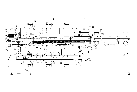
In Figure 1, designated as a whole by 1, is a machine for
continuous coating of cores of products, in particular,
confectionery products. The machine 1 comprises a supporting
structure 2 and an overlying hollow drum 3 having a
substantially horizontal axis 4 of its own. The supporting
structure 2 comprises a fixed base 5 and two pairs 6 and 7 of
uprights extending upwards from the base 5 and set on opposite
axial sides of the drum 3. Associated to each pair 6, 7 of
uprights is a respective structural ring 8, 9, which in the
case in point is quadrangular. The ring 8 is hinged to the
uprights 6 so as to tilt about a substantially horizontal
hinge axis 11 orthogonal to the axis 4 and intersected by the
axis 4 itself, whilst the ring 9 is fixedly connected to the
CA 02748102 2011-06-22
WO 2010/073112 PCT/IB2009/007880
7 -
uprights 7.
The drum 3 has two terminal attachment collars 12 and 13
opposed to one another and sharing the same axis 4, of which
the collar 12 is coupled to the ring 8 via a corresponding
thrust bearing fixedly connected to the ring 8 itself, whilst
the collar 13 is coupled to the ring 9 by a corresponding
thrust bearing, the position of which with respect to the ring
9 is adjustable via a set 15 of jacks set between the ring 9
and the corresponding thrust bearing (Figure 3). The set-15 of
jacks enables, 'in particular, variation of the inclination of
the axis 4 of the drum 3 with respect to a horizontal plane
about the hinge axis 11.
The drum 3 is able to rotate about the axis 4 under the thrust
of a motion-reducer assembly 16 carried by the ring 8 and
angularly connected to the corresponding thrust bearing via a
transmission, conveniently of the gear type. The motion-
reducer assembly 16 comprises an electric motor 18, which is
controlled by a command and control unit 19 for rotating the
drum 3 about the axis 4 in a reciprocating or continuous way,
as will be better described in what follows.
Once again with reference to Figure 1, the drum 3 houses
inside it an annular or axially hollow body 20, which is wound
axially in a helix or spiral, is set in contact with the inner
surface 3a of the drum 3, and is fixedly connected to the drum
3 itself for delimiting, together with the inner surface 3a, a
plurality of annular chambers 22. The chambers 22 communicate
with one another through a central duct 23 that shares the
axis 4 and, in turn, communicates with the outside through the
axial openings 12a and 13a delimited, respectively, by the
collars 12 and 13.
Extending through the opening 12a is a belt conveyor 25, in
itself known and not described in detail, for feeding a mass M
CA 02748102 2011-06-22
WO 2010/073112 PCT/IB2009/007880
8 -
of cores to be treated into one of the chambers 22. Extending
through the opening 13a, instead, within the drum 3 is a
delivery assembly 26 for feeding into each of the chambers 22
the materials envisaged for coating the cores to be treated, a
mass of drying air or process air for drying the coating
materials when they are deposited on the cores, and a fluid
for flushing the drum 3.
The delivery assembly 26 comprises a guide rail 27 having an
intermediate stretch 27a, which extends within the drum 3
above and parallel to a horizontal plane P passing through the
axis 4, and two opposite terminal stretches 27b and 27c, which
project axially on the outside of the drum 3 and are
connected, the first to the structural ring 8 and the second
to a supporting upright 28 that stands on the floor. Coupled
to the rail 27 are three carriages 29, each of which supports
a suspended frame 30 of its own, which is shaped substantially
like a T set upside down with two opposed horizontal arms 30a
and 30b (Figures 4 and 6).
The assembly 26 further comprises two delivery devices,
designated by 32 and 33 for feeding, in the case in point, the
first a chocolate-based coating material or other coating
material and the second a coating material with a base of
sugary syrup. Each device 32, 33 in turn comprises a
corresponding feed pipe 32a and 33a connected to the ends of
the horizontal arms 30a and, for at least part of the chambers
22, a corresponding delivery head 32b, 33b, in itself known
and not described in detail, coupled to the respective pipe
32a, 33a in an adjustable way at the inlet of the
corresponding chamber 22. Each delivery head 32b and 33b has
at least one respective delivery nozzle 32c, 33c set below the
plane P and in an inlet of the corresponding chamber 22 for
spraying the material received from the respective pipe 32a,
33a towards the inner surface 3a of the drum 3 and, in use,
onto the mass M of material treated in the chamber 22 itself.
CA 02748102 2011-06-22
WO 2010/073112 PCT/IB2009/007880
9 -
The assembly 26 then comprises a device 35 for drying the
sprayed coating materials; the device 35 comprises a common
duct 36 for introduction of a mass of air common to all the
chambers 22 and a duct 37 for extraction of the air present in
the drum 3, both of which are stably connected to the
aforesaid frames 30 and both of which present respective
stretches set within the drum 3 itself having a section that
increases towards an outlet 38 of the drum 3.
In greater detail, the extraction duct 37 extends in a raised
position substantially along the rail 27, whilst the duct 36
for introduction of the air is set in a lowered position with
respect to the extraction duct 37 and is connected to the arms
30b substantially at the same height as, but in a position set
laterally at a distance from, the ducts 32a, 33a for feeding
the coating materials. For each of the chambers 22, the device
35 then comprises a corresponding delivery duct 40, which has
an inlet communicating with the inlet duct 36, and an outlet
41 oriented towards the inner surface 3a of the drum 3 and set
once again on the opposite side of the outlets of the nozzles
32c, 33c with respect to a vertical plane P1 passing through
the axis 4 of the drum and orthogonal to the plane P, as may
be seen in Figures 4-6. The ducts 40 are carried by an
attachment structure 42 of their own, coupled to the frames 30
in an adjustable way about the axis of the inlet duct 36 so as
to enable adjustment of the angular position of the duct 40
itself between two extreme end-of-travel angular positions.
In the proximity of the corresponding outlet 41, each delivery
duct 40 carries a conditioning and distribution assembly 43
for forming a dedicated drying air flow directed at the
material present in the corresponding chamber 22. In
particular, each assembly 43 comprises a respective
conditioning device 44 (illustrated schematically),
independent of the other conditioning devices 44, for varying
CA 02748102 2011-06-22
WO 2010/073112 PCT/IB2009/007880
- 10 -
the temperature of the drying air introduced into the
corresponding chamber 22, and a device 45 for distributing
said drying air flow. In the particular example described, the
distribution device 45 comprises a perforated partition wall,
which can be chosen from among a plurality of partition walls
which differ from one another in size, geometry, and
distribution of the perforations so as to divide and orient
the flow of air directed onto the corresponding mass of cores
being coated in different ways.
Finally, the assembly 26 comprises a flushing device 47, which
in turn comprises a pipe 48 for inlet of a flushing liquid
connected to the arms 30b in a position set alongside the
inlet pipe 36 and a plurality of nozzles 49 facing the inner
surface 3a and set substantially in the horizontal plane P.
With specific reference to Figures 9 and 10, housed within
each of the chambers 22 is a ring of mixing ploughshares 50,
which extend towards the axis 4 starting from the inner
surface 3a of the drum 3, to which the ploughshares 50 are
coupled in an adjustable way, each, via a respective
projecting angular adjustment device 51 that can be actuated
from outside the drum 3 independently of the other devices 51.
Each device 51 comprises a faceted supporting pin 52, which is
hexagonal in the particular example described and one end of
which is stably connected to the corresponding ploughshare 50
and extends on the outside of the drum 3 through a
corresponding opening and within a sleeve 55 external to the
drum 3 itself, and terminates with a handwheel 56 for rotation
and positioning of the ploughshare 50. The sleeve 55 has a
stretch with a' shape complementary to that of the pin 52 for
setting and withholding the ploughshare 50 in a plurality of
pre-set angular positions according to the number and
arrangement of the facets, and carries a pair of radial
grubscrews 57 for blocking, in a releasable way, the pin 52 so
that it couples with the complementary stretch of the sleeve
CA 02748102 2011-06-22
WO 2010/073112 PCT/IB2009/007880
- 11 -
55.
Operation of the machine 1 will now be described considering,
for simplicity of exposition, a single mass M of cores to be
treated and starting from the condition (illustrated in Figure
1) where the drum 3 is stationary in a zero or resting
position thereof, and the mass M or bed of cores to be treated
fed by the conveyor is set on the bottom of the second of the
chambers 22.
Starting from said condition, maintaining the mass in the
aforesaid second chamber 22, the command and control unit 19
of the motor 18, on the basis of a program of
displacement/ coating stored in a memory block of the unit 19
itself, issues a command to the motor 18 for it to rotate
cyclically and for a given period of time the drum 3 first in
one direction of rotation, for example in a counterclockwise
direction (Figure 8), through a pre-set angle, conveniently
equal to or less than 1800, and then in the opposite direction
(clockwise in Figure 7) by an angle equal or comparable to the
previous one. During said reciprocating cyclic rotation of the
drum 3, the mass M of cores shifts, arranging itself once
again cyclically in two different angled extreme positions
that face one another and are set symmetrically on opposite
sides of the vertical plane P1, as may be seen in Figures 7
and 8. Once again during rotation whether in one direction or
in the other, the cores, as a result of the rotation of the
drum 3 and of the combined actions of the ploughshares 50 and
of the walls delimiting the chamber 22, are continuously mixed
and progressively taken in positions facing the delivery heads
32b and 33b and the outlets 41 of the ducts 40.
Simultaneously with rotation of the drum 3 in a
counterclockwise direction, via the delivery head 32b
corresponding to the chamber 22 in which the cores are set the
chocolate-based material is sprayed on the cores. Once the
CA 02748102 2011-06-22
WO 2010/073112 PCT/IB2009/007880
- 12 -
angle of rotation set has been reached, the command and
control unit 19 acts on the motor 18 and reverses the
direction of rotation of the drum 3, causing a mixing of the
cores opposite to the first. Mixing in one direction and in
the other favours adhesion of the coating material to the
cores and formation of a first layer of at least partial
coating of the cores. Once the zero or resting position of the
drum 3 has been exceeded, the cores coated with the coating
material previously sprayed are subjected to the flow of
process air previously set both as regards temperature and as
regards distribution by acting on the corresponding assembly
43 (Figure 7) . The flow of air fed in impinges upon the cores
and causes a progressive solidification and stabilization of
the material present on the cores themselves. Since all the
cores are continuously mixed, also in this step of clockwise
rotation, once again as a result of the combined action of the
ploughshares 50 and of the walls delimiting the chamber 22,
the solidification and stabilization of the coating material
is homogeneous throughout the mass of cores.
The operations of cyclic rotation of the drum 3 in opposite
directions, as well as both or just one of the operations of
spraying and/or of drying described above are repeated
cyclically for a given period of time such that all the
coating material fed is finally applied on the cores.
According to the material to be coated, the type of the
coating material, and the thickness of the layer to be
produced on the cores, it may be necessary to carry out the
operations of spraying and drying at different times and/or
with different flows of drying air or simply keep the
partially coated cores in relative motion and in a controlled
atmosphere. For this reason, once the treatment is completed
in one of the chambers 22, the drum 3 is rotated in just one
direction through 360 , and the mass M is fed by one step and
displaced into an adjacent chamber 22, where, once again
simultaneously with a further step of cyclic oscillation of
CA 02748102 2011-06-22
WO 2010/073112 PCT/IB2009/007880
- 13 -
the drum 3, a further treatment of the cores is performed, as
described previously. The alternation of a step of cyclic
oscillation with a step of advance by one step continues until
a first homogeneous layer of desired thickness is obtained,
involving a block or succession of chambers 22 that may vary
from one coating process to another.
Regardless of the number of chambers 22 used, once formation
of the first layer has been completed, the drum 3 is again
rotated in just*one direction of rotation by an angle of 3600
and the coated cores are displaced by a further step and
transferred into an adjacent chamber 22, in which the second
coating with the sugary syrup begins. As in the case of
coating with the first material, also coating with said second
material is performed by alternating one or more steps of
cyclic oscillation of the drum 3 with one or more steps of
feed by steps of the cores, performing, during one or more
steps of cyclic oscillation, an operation of spraying of the
second coating material during counterclockwise rotation of
the drum 3 and an operation of drying during its clockwise
rotation. As in the case of formation of the first layer, also
the operation of formation of the second layer can, according
to the cases, involve one chamber 22 or a block of adjacent
chambers 22.
Whenever a step of the process of coating with sugar is
completed, the drum 3 is again rotated in just one direction
through 360 , and the coated cores are fed by one step, and so
forth until they reach the outlet 38 of the drum 3 and are
emptied off the machine.
From practical experimental tests it has been possible to
verify that the constructional characteristics of the machine
1 and, in particular, the fact of providing a drum with
annular chambers set alongside one another and of rotating the
drum 3 itself cyclically in angularly opposite directions for
CA 02748102 2011-06-22
WO 2010/073112 PCT/IB2009/007880
- 14 -
a given period of time before transferring the cores into a
subsequent treatment chamber limits, as compared to known
solutions, rolling of the cores being treated inside the drum
3 and, consequently, any rubbing of the cores either against
the internal surfaces of the drum 3 and- of the body 20 or
against one another, thus drastically reducing any shattering
and undesirable formation of crumbs and powder, whatever the
material constituting the cores, including particularly
friable ones, and whatever the geometry of the cores
themselves.
In addition, the cyclic rotation in opposite directions of the
drum 3 during the step of coating enables variation, as
compared to known solutions in which the drum rotates in just
one direction, of the relative position of the delivery heads
32b and 33b and of the corresponding outlets 41 of the duct
for delivery of the drying air, thus preventing the aforesaid
interference between the material supplied and the drying air
flow. In fact, in the machine 1, during oscillation of the
drum 3, the mass of the cores is sequentially set in two
distinct positions corresponding to the two different and
opposite directions of rotation, and this enables delivery of
the coating material and of the drying air flow in two
divergent directions substantially opposed to one another. In
this way, the coating material does not contaminate the
outlets for the drying air, and the drying air itself does not
perturb the action of spraying of the coating material, with
the result that both of the adjustments are facilitated
enormously.
In the machine 1 described, the conditioning and distribution
assemblies 43 set on the outlets of each of the delivery ducts
enable, in each of the chambers 22, a pre-defined drying
air flow to be obtained that is specific for the individual
35 chamber and is independent of the flows of the other chambers
22. In this way, each chamber 22, together with its delivery
CA 02748102 2011-06-22
WO 2010/073112 PCT/IB2009/007880
- .15 -
head 32b, 33b and with its duct 40 for delivery of the air is
practically equivalent to a single or independent rotary
coating pan.
As regards, instead, the constructional aspect, as compared to
known solutions, the machine 1 described is particularly
simple, uses a single motor, and above all does not include
members, coupled to one another in a fluid-tight way and
mobile with respect one another, for delimiting the chambers.
Finally, the machine 1 described is easy to clean and the very
angular oscillation in opposite directions of the drum 3
facilitates considerably the cleaning operations, which, on
the other hand, do not require any removal of components
internal to the drum.
From the foregoing description it emerges clearly how
modifications and variations may be made to the machine 1 and
to the method described, without thereby departing from the
sphere of protection defined by the independent claims.
In particular, the drum 3 could comprise a number of chambers
22 different from the one indicated by way of example, and
delivery devices different from the ones indicated. In
particular, the machine could comprise a number of delivery
devices different from the one indicated in the case where it
were sufficient to feed just one coating material or more than
two coating materials.
Finally, from the foregoing description it emerges clearly how
the machine and the method described can be used for any
product and whenever there is the problem of preventing
crumbling and in general deterioration, abrasion, or chipping
of the products to be coated.