Note : Les descriptions sont présentées dans la langue officielle dans laquelle elles ont été soumises.
CA 02752598 2011-09-02
FLEXIBLE DOWNSPOUT EXTENSION
FIELD OF THE INVENTION
This invention relates generally to an apparatus for conveying
rainwater away from a downspout and, more particularly, to a downspout
extension
that provides a connector adapted to engage substantially any known
conventional
downspout configuration without restricting the flow from one end of the
downspout
extension to the other.
BACKGROUND OF THE INVENTION
Gutters and downspouts are mounted on most residential and
commercial structures along the lower edge of the roof of the structure to
receive
water draining off of the roof, such as during a rainstorm. Gutters come in
many
different styles, including K gutter, half round gutter, or commercial box
gutter, but all
are generally formed with an open top through which water is received into a
trough
or channel that delivers the water by gravity to a downspout for discharge
away from
is the building structure. Gutters are often mounted on a plurality of hangers
that are
spaced along the length of the gutter and fastened to fascia boards by nails
or
screws such that the gutter is suspended from the hangers. The downspout is
connected to an outlet of the gutter to provide a conduit to drain the
collected
rainwater from the gutter for discharge along the surface of the ground and
direct the
rainwater away from the building structure.
Typically, the downspout is provided with an elbow at the discharge
end thereof to direct the discharged rainwater into a generally horizontal
direction
CA 02752598 2011-09-02
2
away from the building on which the downspout is mounted. These elbows at the
discharge end of the downspout have a short length and are only effective to
provide
a direction for the discharge of the rainwater away from the building;
therefore, the
rainwater is often discharged too close to the building and the discharged
rainwater
s can find a way into the basement of the building to cause cracks or leaks.
Splashblocks can be provided to receive the discharged rainwater from the
downspout elbow and help direct the rainwater away from the building. Other
attempts to divert the rainwater from downspouts include a non-flexible
extension,
which is typically a generally horizontally disposed piece of downspout
affixed to the
discharge end of the elbow, and a flexible downspout extension that can be
bent in a
desired direction to redirect the discharged rainwater.
Occasionally, a landowner will bury into the ground a drainage pipe or
conduit for conveying rainwater to a remote location, such as a groundwater
restoration cistern, or at least some point remotely distant from the
building. The
1s downspout is then connected to the drainage pipe by the downspout extension
so
that the rainwater is discharged at a location that will not infiltrate into
the basement
of the building. Once such downspout extension can be found in U.S. Patent No.
5,813,701, granted to Christopher Noble on September 29, 1998. The Noble
downspout extension is formed with multiple adaptor portions at each end of a
flexible central portion. The adaptor segments at the respective ends of the
downspout extension are separated by a cut line to allow the installer of the
downspout extension to separate the outwardmost adaptor segment from the
CA 02752598 2011-09-02
3
downspout extension so that the inner adaptor segment could be utilized to
connect
to the downspout. The Noble downspout extension is formed so that the adaptor
segments at one end of the downspout extension will be capable of fitting into
the
corresponding adaptor segment at the opposing end of the downspout extension
so
that multiple downspout extensions can be hooked together in a serial manner.
In U. S. Patent No. 6,041,825, granted to Jeffrey Smith and
Christopher Noble on March 28, 2000, the downspout extension was formed with
multiple adaptor segments at each end of the flexible central portion of the
downspout extension. More particularly, the adaptor segments begin with a
large
rectangular configuration on the outwardmost ends of the downspout extension
followed inwardly by a smaller rectangular adaptor segment and then inwardly a
smaller circular adaptor segment. Each adaptor segment is separable from the
inwardly disposed adaptor segment by a cut line so that the outward adaptor
segments can be removed. Accordingly, when the outwardmost adaptor segment
was utilized to connect to the discharge end of the downspout, the rainwater,
and
any debris entrained within the flow of the rainwater had to pass from a
larger
adaptor configuration into a smaller adaptor configuration, thus forming a
restriction
on the flow through the downspout extension.
A differently configured flexible downspout extension is disclosed in U.
S. Patent No. 7,017,614 granted on March 28, 2006, to Stephen Handley. In the
Handley downspout extension, one end of the downspout extension was formed
with
multiple rectangular adaptor segments arranged in decreasing sizes from the
CA 02752598 2011-09-02
4
outwardmost adaptor segment to the innermost adaptor segment, while the
opposing end of the downspout extension was provided with circular connector
sized
for attachment to a circular drainage pipe or conduit. Thus, one end of the
flexible
downspout extension is formed for connection to a downspout, while the
opposing
end is formed for connection to a drainage pipe. As with the Noble downspout
extensions, the connection of the downspout to the outwardmost adaptor segment
causes the flow to be constricted through decreasingly smaller adaptor
segments
before reaching the central flexible portion.
None of the known downspout extensions are configured to be
connected to all of the known conventional sizes of downspouts. Conventional
gutters and corresponding downspouts are formed in a number of different sizes
and
configurations resulting in the downspout being formed in a 2 inch by 3 inch
or a 3
inch by 4 inch rectangular shape, a 3 inch by 3 inch square shape, or a 3 inch
round
or a 4 inch round shape. These five downspout configurations cover a large
majority
of downspouts. The most common configurations of downspouts are the 2 inch by
3
inch and the 3 inch by 4 inch rectangular shapes. Drainage conduits are
typically
circular and are mostly 4 inches in diameter, although a 3 inch circular
conduit can
also be utilized.
It would be desirable to provide a downspout extension that is
configured to provide a connector segment for each common conventional size
and
shape of downspout, arranged in a manner that flow through the downspout
CA 02752598 2011-09-02
extension is not constricted as it passes into the central flexible portion
that can be
bent to direct the flow of rainwater into a desired direction in into a
desired receiver.
SUMMARY OF THE INVENTION
5 According to a first aspect of the invention there is provided a
downspout extension for connection to a discharge end of a downspout mounted
on
a building structure, comprising:
a flexible central portion having first and second ends, said flexible
central portion being formed with corrugations that allow said first end to be
moved
relative to said second end; and
first and second connector ends integrally formed with said first and
second ends, respectively, of said flexible central portion, said respective
said
connector end including at least two connector segments arranged in
progressively
decreasing cross-sectional areas from the corresponding said end of said
corrugated central portion.
According to a second aspect of the invention there is provided, in a
downspout extension for connection to a discharge end of a downspout mounted
on
a building structure, said downspout extension having a corrugated central
portion
having first and second ends, the improvement comprising first and second
connector ends integrally formed with said first and second ends,
respectively, of
said corrugated central portion, said respective said connector end including
at least
CA 02752598 2011-09-02
6
two connector segments arranged in progressively decreasing cross-sectional
areas
from the corresponding said end of said corrugated central portion.
According to a third aspect of the invention there is provided a
downspout extension interconnecting a discharge end of a downspout mounted on
a
building structure and a drainage conduit to convey rainwater from said
downspout
away from said building structure, comprising:
a flexible central portion having first and second ends, said flexible
central portion being formed with corrugations that allow said first end to be
moved
relative to said second end;
a rectangular connector end integrally formed with said first end of said
flexible central portion, said rectangular connector end having at least two
rectangular connector segments including an innermost rectangular connector
segment with a first cross-sectional area and an outermost rectangular
connector
segment with a second cross-sectional area, said first cross-sectional area
being
larger than said second cross-sectional area; and
a circular connector end integrally formed with said second end of said
flexible central portion, said circular connector end having at least two
circular
connector segments including an innermost circular connector segment with a
third
cross-sectional area and an outermost circular connector segment with a fourth
cross-sectional area, said third cross-sectional area being larger than said
fourth
cross-sectional area.
CA 02752598 2011-09-02
7
to overcome the disadvantages of the prior art by providing a downspout
extension
formed with a multiple connector segments that will connect to a majority of
downspout configurations,
to provide a downspout extension that is arranged so that rainwater
and debris entrained within the rainwater will not be constricted in flowing
into the
central flexible portion of the downspout extension.
that the connector segments corresponding to the most utilized
downspout configurations are formed at one end of the downspout extension.
that the connector segments corresponding to the most utilized
drainage conduit configurations are formed at the end of the downspout
extension
opposite the end on which the downspout connectors are formed.
The arrangement described in more detail hereinafter may provide one
or more of the following features:
that the connector segments are arranged at each respective end of
the downspout extension in an increasing size from the outwardmost connector
segment to the innermost connector segment and to the central flexible
portion.
that rainwater and debris entrained within the flow of rainwater passing
through the discharge end of the downspout is not constricted by the structure
of the
downspout extension into the flexible central portion.
that each of the multiple connector segments at each respective end of
the downspout extension incorporate a cut line to allow the separation of the
outward connector segments from the downspout extension.
CA 02752598 2011-09-02
8
that most uses of the downspout extension will result in one of the
rectangular connector segments being affixed to the discharge end of the
downspout, while the opposing end of the downspout is connected to a discharge
conduit.
that the rainwater discharged from a downspout into the downspout
extension will not be passed through an opening having a smaller cross-
sectional
area than the downspout to pass into the flexible central portion of the
downspout
extension.
that the flexible central portion of the downspout extension has a larger
cross-sectional area than any of the connector segments at either end of the
downspout extension.
that the connector segments located next to the flexible central portion
to either end thereof have approximately the same cross-sectional area.
that the passage of rainwater into the flexible central portion from the
connector segment at either end of the central portion will not be restricted
exiting
the opposing end of the flexible central portion into the opposing connector
segment.
to provide a downspout extension that has a substantially unrestricted
flow through capability into and out of the flexible central portion thereof.
to provide a downspout extension that is connectable to the discharge
end of a downspout to direct rainwater away from the building on which the
downspout is mounted, which is durable in construction, inexpensive of
CA 02752598 2011-09-02
9
manufacture, carefree of maintenance, facile in assemblage, and simple and
effective in use.
The arrangement as described in more detail hereinafter provides
generally a downspout extension which has multiple connector segments at each
opposing end of a flexible central portion to allow the connection of the
downspout
extension to substantially any conventional downspout configuration. The
multiple
connector segments at each respective end of the downspout extension are
arranged in order of increasing size in terms of cross-sectional area from the
outermost segment to the connector segment adjacent the central portion.
Rectangular segment configurations are located at one end of the downspout
extension to correspond to the majority of conventional downspout
configurations,
while the opposing end of the downspout extension is formed with circular
connector
segments which for connection to drainage pipes so that the downspout
extension
will direct rainwater from the downspout into the drainage pipe. Cut lines are
formed
adjacent to each of the connector segments to facilitate the removal of the
outermost
connector segments when the smaller connector segments are not needed.
BRIEF DESCRIPTION OF THE DRAWINGS
The following provides a detailed disclosure of one embodiment of the
invention, especially when taken in conjunction with the accompanying drawings
wherein:
CA 02752598 2011-09-02
Fig. 1A is a front elevational view of the rectangular connector end of a
downspout extension incorporating the principles of the instant invention, the
flexible
central portion of the downspout extension being broken away along with the
opposing connector end;
5 Fig. 1 B is a front elevational view of the circular connector end of the
downspout extension opposite of the rectangular connector end shown in Fig.
1A,
the flexible portion of the downspout extension being broken away;
Fig. 2A is a side elevational view of the portion of the downspout
extension showing the rectangular connector end depicted in Fig. 1A;
10 Fig. 2B is a side elevational view of the portion of the downspout
extension showing the circular connector end depicted in Fig. 1 B;
Fig. 3 is a perspective view of the downspout extension shown in Figs.
1A through 2B, the middle of the flexible central portion being broken away
for
purposes of clarity;
Fig. 4 is an enlarged top plan view of the downspout extension looking
into the rectangular end; and
Fig. 5 is an enlarged top plan view of the downspout extension similar
to that of Fig. 4, but depicting as dashed lines the hidden portions of the
connector
segments at the circular connector end.
DETAILED DESCRIPTION
CA 02752598 2011-09-02
11
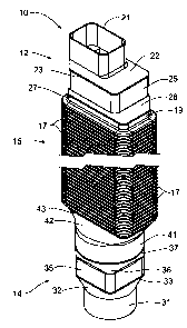
Referring now to the drawings, a downspout extension incorporating
the principles of the instant invention can best be seen. The downspout
extension
is formed from plastic and has a central flexible portion 15 formed in a
conventional manner with corrugated pleats 17 that permit the central portion
15 to
5 bend in substantially any direction. A rectangular connector end 12 is
integrally
formed on one end of the flexible central portion 15, while a circular
connector end
14 is integrally formed on the opposing end of the flexible central portion
15. The
connector ends 12, 14 are formed with multiple connector segments, as will be
described in greater detail below, for connection of the downspout extension
10 to
10 either a downspout (not shown) mounted in a conventional manner on a
building,
and/or to a drainage pipe (not shown) that is typically buried to provide a
conduit for
rainwater to be conveyed away from the building on which the downspout is
mounted.
The rectangular connector end 12 is best seen in Figs. 1A, 2A and 3.
1s The rectangular connector end 12 has a first rectangular connector segment
21 at
the distal end of the downspout extension 10. This first connector segment 21
is
preferably sized to mount onto a two inch by three inch rectangular downspout
(not
shown), which is one of the conventional downspout sizes. A second rectangular
connector segment 25 is formed inwardly of the first rectangular connector
segment
21 so as to be located between the flexible central portion 15 and the first
connector
segment 21. The second connector segment 25 is sized to fit over and mount to
a
CA 02752598 2011-09-02
12
three inch by four inch rectangular downspout (not shown), which is also a
conventional downspout size.
A first transition area 22 is integrally formed between the first
connector segment 21 and the second connector segment 25 to provide a smooth
transition from the first rectangular connector segment 21 and the second
rectangular connector segment 25 for the flow of rainwater from the first
connector
segment 21 to the central portion 15. At the inward edge of the first
transition area
22 lies a first cut groove 23 that is positioned at the outermost edge of the
second
connector segment 25. The cut groove 23 defines a thinned area of the plastic
material at which a knife or other sharp instrument can be inserted to
separate the
first connector segment 21 and the first transition area 22 from the second
rectangular connector segment 25. In this manner, the second connector segment
25 can be secured to a suitably sized downspout and the first connector
segment 21
and associated transition area 22 thrown away.
A second transition area 26 is also provided between the second
rectangular connector segment 25 and the inside flange 19 of the corrugated
central
portion 15. A second cut groove 27 is also provided at the junction of the
second
transition area 26 and the inside flange 19 adjacent the rectangular connector
end
12 to allow the entire rectangular connector end 12 to be separated from the
flexible
central portion 15. The two rectangular connector segments 21, 25 represent
the
two most common downspout sizes utilized on residential building construction.
Thus, the downspout extension 10 is configured with the two connector segments
CA 02752598 2011-09-02
13
representing the most frequently found rectangular downspouts so that in most
cases one of the rectangular connector segments 21, 25 will be utilized to
connect to
the discharge end of a downspout.
The circular connector end 14 is formed in a similar manner to the
rectangular connector end 12, but with differently configured connector
segments, as
will be described in greater detail below. Where the rectangular connector end
12 is
configured to be utilized most frequently for connection to a downspout, the
circular
connector end 14 is configured to be connected most frequently to a drainage
pipe
that conveys rainwater away from the building on which the downspout is
mounted.
Accordingly, the outermost circular connector segment 31 is sized to
be connected to a three inch diameter drainage conduit (not shown). One
skilled in
the art will recognize that downspouts are also formed in a circular
configuration
having a three inch diameter. Therefore, the outermost circular connector
segment
31 can be utilized to connect as needed to either a downspout or a drainage
pipe.
is Inwardly from the outermost circular connector segment 31 is formed a
square three
inch by three inch connector segment 35 that is sized to connect to a
corresponding
three inch square downspout. A third transition area 32 lies between the
outermost
circular connector segment 31 and the square connector segment 35 to provide a
smooth flow of rainwater from the smaller three inch diameter circular
connector
segment 31 to the slightly larger three inch square connector segment 35. A
cut
groove 33 is formed at the inner end of the third transition area 32 at the
edge of the
square connector segment 35 to allow the outermost circular connector segment
31
CA 02752598 2011-09-02
14
to be removed from the downspout extension 10 and allow the utilization of the
square connector segment 35.
Further inwardly from the square connector segment 35 lies a second
circular connector segment 41 sized to mount to a four inch drainage pipe, or
to a
four inch diameter, circular downspout. The most commonly used drainage pipes
are four inch diameter plastic corrugated conduits that are belled at one end
for
connection to another section of drainage pipe (not shown), on in this
situation to the
four inch diameter connector segment 41. A fourth transition area 36 extends
from
the inner end of the square connector segment 35 to the outer edge of the four
inch
zo diameter circular connector segment 41, terminating in a fourth cut groove
37 that
allows both the three inch diameter connector segment 31 and the three inch
square
connector segment 35, along with the third and fourth transition areas 32, 36,
to be
removed from the four inch circular connector segment 41 so that this
connector
segment 41 can be utilized.
A fifth transition area 42 extends from the inner edge of the four inch
circular connector segment 41 to the adjacent inside flange 19 of the
corrugated
central portion 15 with a fifth cut groove 43 being formed at the joint
between the
inside flange 19 and the fifth transition area 42 to permit the removal of the
entire
circular connector end 14 from the central portion 15. The three and four inch
diameter connector segments 31, 41 represent the most commonly utilized
drainage
pipe sizes, with the four inch drainage conduit being more popular than the
three
inch diameter version. Thus, the rectangular connector end 12 is most
frequently
CA 02752598 2011-09-02
used to connect to the discharge end of a downspout while the circular
connector
end 14 is most frequently utilized to connect to common drainage pipes to
permit
rainwater to be transported from the downspout through the downspout extension
and outwardly through the drainage pipe.
5 For those instances where the circular connector end 14 is utilized to
connect to a circular or to a square downspout, the opposing rectangular
connector
end 12 would require an appropriate rectangular-to-circular adaptor to permit
connection thereof to a typical drainage pipe. Such connectors can be found in
configurations that will connect to either the first or the second rectangular
connector
10 segment 21, 25; however, the second rectangular connector segment 25 would
be
the segment preferably used so that the first rectangular connector segment 21
does
not present a restriction in size for the movement of rainwater through the
downspout extension 10.
One skilled in the art will recognize that the connector segments on
15 each of the connector ends 12, 14 are arranged in an increasing size, as
defined by
the cross-sectional area of the respective connector segment, from the distal
end of
the downspout extension 10 to the central corrugated portion 15. At the
rectangular
connector end 12, the smaller 2 x 3 connector segment 21 is outside of the
larger 3
x 4 rectangular connector segment 25. At the circular connector end 14, the
outermost three inch diameter circular connector segment 31 is smaller than
the
inwardly positioned 3 x 3 square connector segment 35, which in turn is
smaller than
the innermost four inch circular connector segment 41. The central corrugated
CA 02752598 2011-09-02
16
portion preferably has a rectangular central opening through the portion of
two and a
half inches by five inches to provide a cross-sectional area that is
substantially the
same as the cross-sectional area of the adjacent connector segments 25, 41 at
opposing ends thereof. Thus, the downspout extension 10 expands in cross-
sectional area from one connector segment to another through to the flexible
central
portion 15 and also to the next adjacent connector segment. In situations
where the
downstream end of the downspout extension 10 is connected to a four inch
drainage
pipe, the downspout extension 10 provides a non-constrictive flow path from
the
downspout to the drainage pipe.