Sélection de la langue

Search

Sommaire du brevet 2752795 

Énoncé de désistement de responsabilité concernant l'information provenant de tiers

Une partie des informations de ce site Web a été fournie par des sources externes. Le gouvernement du Canada n'assume aucune responsabilité concernant la précision, l'actualité ou la fiabilité des informations fournies par les sources externes. Les utilisateurs qui désirent employer cette information devraient consulter directement la source des informations. Le contenu fourni par les sources externes n'est pas assujetti aux exigences sur les langues officielles, la protection des renseignements personnels et l'accessibilité.

Disponibilité de l'Abrégé et des Revendications

L'apparition de différences dans le texte et l'image des Revendications et de l'Abrégé dépend du moment auquel le document est publié. Les textes des Revendications et de l'Abrégé sont affichés :

  • lorsque la demande peut être examinée par le public;
  • lorsque le brevet est émis (délivrance).
(12) Brevet: (11) CA 2752795
(54) Titre français: APPAREILLAGE DE COMMUTATION ELECTRIQUE ET ENSEMBLE A LEVIER CONNEXE
(54) Titre anglais: ELECTRICAL SWITCHING APPARATUS AND LEVERING ASSEMBLY THEREFOR
Statut: Accordé et délivré
Données bibliographiques
(51) Classification internationale des brevets (CIB):
  • H02B 11/02 (2006.01)
(72) Inventeurs :
  • POLLITT, WILLIAM C. (Etats-Unis d'Amérique)
  • GULA, LANCE (Etats-Unis d'Amérique)
  • WEISTER, NATHAN J. (Etats-Unis d'Amérique)
  • RODGERS, CRAIG A. (Etats-Unis d'Amérique)
  • PRINCE, EDWARD A. (Etats-Unis d'Amérique)
(73) Titulaires :
  • EATON INTELLIGENT POWER LIMITED
(71) Demandeurs :
  • EATON INTELLIGENT POWER LIMITED (Irlande)
(74) Agent: SMART & BIGGAR LP
(74) Co-agent:
(45) Délivré: 2018-02-27
(22) Date de dépôt: 2011-09-20
(41) Mise à la disponibilité du public: 2012-03-20
Requête d'examen: 2016-09-07
Licence disponible: S.O.
Cédé au domaine public: S.O.
(25) Langue des documents déposés: Anglais

Traité de coopération en matière de brevets (PCT): Non

(30) Données de priorité de la demande:
Numéro de la demande Pays / territoire Date
12/886,038 (Etats-Unis d'Amérique) 2010-09-20

Abrégés

Abrégé français

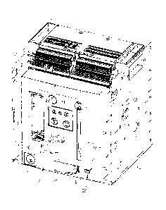
Un dispositif de levier est présenté destiné à un appareil de commutation électrique, comme un disjoncteur, qui est disposé de manière amovible dans une cassette. Le dispositif de levier comprend un élément dinstallation couplé au logement du disjoncteur. Un mécanisme dentraînement est couplé à lélément dinstallation et coopère avec la cassette. Un actionneur alimenté, comme un moteur électrique, est disposé sur lélément dinstallation et actionne le dispositif de levier à déplacer le disjoncteur par rapport à la cassette. Lactionneur alimenté est disposé dans le logement du disjoncteur. Lélément dinstallation, le dispositif dentraînement et lactionneur alimenté forment un sous-ensemble autonome, qui est substantiellement disposé derrière le couvercle du disjoncteur. Le dispositif de levier peut être actionné à partir dun endroit distant afin de déplacer automatiquement le disjoncteur par rapport à la cassette, pour offrir une sûreté améliorée entre autres avantages.


Abrégé anglais

A levering assembly is provided for an electrical switching apparatus, such as a circuit breaker, which is removably disposed in a cassette. The levering assembly includes a mounting member coupled to the housing of the circuit breaker. A drive assembly is coupled to the mounting member and cooperates with the cassette. A powered actuator, such as an electric motor, is disposed on the mounting member and actuates the drive assembly to move the circuit breaker with respect to the cassette. The powered actuator is disposed within the housing of the circuit breaker. The mounting member, drive assembly and powered actuator form a self-contained sub- assembly, which is substantially disposed behind the circuit breaker cover. The levering assembly is operable from a remote location to automatically move the circuit breaker with respect to the cassette, to provide enhanced safety among other benefits.

Revendications

Note : Les revendications sont présentées dans la langue officielle dans laquelle elles ont été soumises.


What is claimed is:
1. A levering assembly for an electrical switching apparatus structured to
be
removably disposed in a cassette, said electrical switching apparatus
including a housing,
said levering assembly comprising:
a mounting member structured to be coupled to the housing;
a drive assembly coupled to said mounting member and being structured to
cooperate with said cassette; and
a powered actuator disposed on said mounting member and being structured to
actuate said drive assembly to move said electrical switching apparatus with
respect to
said cassette,
wherein said drive assembly comprises a drive shaft, a plurality of gears, and
a
number of racking members; wherein said racking members are structured to be
movably
coupled to said cassette; and wherein said powered actuator is structured to
move said
gears and said drive shaft, thereby moving said racking members to rack said
electrical
switching apparatus into or out of said cassette,
wherein said mounting member comprises a frame and a mount; wherein said
frame includes a first side and a second side disposed opposite and distal
from the first
side; wherein said mount extends between the first side and the second side;
wherein said
drive shaft is pivotably coupled to said mount; and wherein said powered
actuator is
disposed on said mount proximate to said drive shaft,
wherein said plurality of gears comprises a drive rack, a drive gear, and a
number
of racking gears; wherein said drive gear and said racking gears are coupled
to said drive
shaft; wherein each of said racking gears is structured to cooperate with a
corresponding
one of said racking members; and wherein said powered actuator is structured
to move
said drive rack, thereby pivoting said drive gear, said drive shaft and said
racking gears to
move said racking members, and
wherein said drive shaft includes a first end and a second end disposed
opposite
and distal from the first end; wherein said number of racking gears is a first
racking gear
coupled to said drive shaft at or about the first end, and a second racking
gear coupled to
said drive shaft at or about the second end; wherein said drive gear is
coupled to said
drive shaft between the first end and the second end; wherein said number of
racking
members is a first racking member and a second racking member disposed
opposite and
-7-

distal from said first racking member; wherein said first racking gear engages
and moves
said first racking member; and wherein said second racking gear engages and
moves said
second racking member.
2. The levering assembly of claim 1 wherein said powered actuator is
structured to
be disposed within the housing of said electrical switching apparatus.
3. The levering assembly of claim 1 wherein said powered actuator is
operable from
a remote location.
4. The levering assembly of claim 1 wherein said powered actuator is an
electric
motor; wherein said electric motor includes a pinion; and wherein said pinion
moves said
drive rack.
5. A levering assembly for an electrical switching apparatus structured to
be
removably disposed in a cassette, said electrical switching apparatus
including a housing,
said levering assembly comprising:
a mounting member structured to be coupled to the housing;
a drive assembly coupled to said mounting member and being structured to
cooperate with said cassette; and
a powered actuator disposed on said mounting member and being structured to
actuate said drive assembly to move said electrical switching apparatus with
respect to
said cassette,
wherein said mounting member, said drive assembly and said powered actuator
form a self-contained sub-assembly; wherein the housing of said electrical
switching
apparatus includes a cover; and wherein said self-contained sub-assembly is
structured to
be substantially disposed behind said cover, and
wherein said self-contained sub-assembly is operable to automatically move
said
electrical switching apparatus with respect to said cassette, without any
separate actuators
external to said electrical switching apparatus.
6. The levering assembly of claim 5 wherein said powered actuator is
structured to
be disposed within the housing of said electrical switching apparatus.
-8-

7. The levering assembly of claim 5 wherein said powered actuator is
operable from
a remote location.
8. An electrical switching apparatus comprising:
a housing; and
a levering assembly structured to move said electrical switching apparatus
into
and out of a cassette, said levering assembly comprising:
a mounting member coupled to the housing,
a drive assembly coupled to said mounting member and cooperating with said
cassette, and
a powered actuator disposed on said mounting member and actuating said drive
assembly to move said electrical switching apparatus with respect to said
cassette,
wherein said drive assembly comprises a drive shaft, a plurality of gears, and
a
number of racking members; wherein said racking members are movably coupled to
said
cassette; and wherein said powered actuator moves said gears and said drive
shaft,
thereby moving said racking members to rack said electrical switching
apparatus into or
out of said cassette,
wherein said mounting member of said levering assembly comprises a frame and a
mount; wherein said frame includes a first side and a second side disposed
opposite and
distal from the first side; wherein said mount extends between the first side
and the
second side; wherein said drive shaft is pivotably coupled to said mount; and
wherein said
powered actuator is disposed on said mount proximate to said drive shaft,
wherein said plurality of gears comprises a drive rack, a drive gear, and a
number
of racking gears; wherein said drive gear and said racking gears are coupled
to said drive
shaft; wherein each of said racking gears cooperates with a corresponding one
of said
racking members; and wherein said powered actuator moves said drive rack,
thereby
pivoting said drive gear, said drive shaft and said racking gears to move said
racking
members, and
wherein said drive shaft includes a first end and a second end disposed
opposite
and distal from the first end; wherein said number of racking gears is a first
racking gear
coupled to said drive shaft at or about the first end, and a second racking
gear coupled to
said drive shaft at or about the second end; wherein said drive gear is
coupled to said
-9-

drive shaft between the first end and the second end; wherein said number of
racking
members is a first racking member and a second racking member disposed
opposite and
distal from said first racking member; wherein said first racking gear engages
and moves
said first racking member; and wherein said second racking gear engages and
moves said
second racking member.
9. The electrical switching apparatus of claim 8 wherein said powered
actuator of
said levering assembly is disposed within the housing of said electrical
switching
apparatus.
10. The electrical switching apparatus of claim 8 wherein said powered
actuator is
operable from a remote location.
11. The electrical switching apparatus of claim 8 wherein said powered
actuator of
said levering assembly is an electric motor; wherein said electric motor
includes a pinion;
and wherein said pinion moves said drive rack.
12. An electrical switching apparatus comprising:
a housing; and
a levering assembly structured to move said electrical switching apparatus
into
and out of a cassette, said levering assembly comprising:
a mounting member coupled to the housing,
a drive assembly coupled to said mounting member and cooperating with said
cassette; and
a powered actuator disposed on said mounting member and actuating said drive
assembly to move said electrical switching apparatus with respect to said
cassette,
wherein said mounting member, said drive assembly and said powered actuator
form a self-contained sub-assembly; wherein the housing of said electrical
switching
apparatus includes a cover; and wherein said self-contained sub-assembly is
substantially
disposed behind said cover, and
wherein said electrical switching apparatus is a circuit breaker; and wherein
said
levering assembly is operable to automatically move said circuit breaker with
respect to
said cassette.
-10-

13. The electrical switching apparatus of claim 12 wherein said powered
actuator of
said levering assembly is disposed within the housing of said electrical
switching
apparatus.
14. The electrical switching apparatus of claim 12 wherein said powered
actuator is
operable from a remote location.
-11-

Description

Note : Les descriptions sont présentées dans la langue officielle dans laquelle elles ont été soumises.


CA 02752795 2016-09-07
ELECTRICAL SWITCHING APPARATUS AND LEVERING
ASSEMBLY THEREFOR
BACKGROUND
Field
The disclosed concept relates generally to electrical switching apparatus
and, more particularly, to electrical switching apparatus, such as circuit
breakers. The
disclosed concept also relates to levering assemblies for circuit breakers.
Background Information
Electrical switching apparatus used in power distribution systems are often
mounted within a switchgear enclosure either individually or in combination
with other
switchgear (e.g., without limitation, circuit switching devices and circuit
interrupters such
as circuit breakers, contactors, motor starters, motor controllers and other
load
controllers).
Some electrical switching apparatus such as, for example, some medium-
voltage and low-voltage circuit breakers, can be relatively large. In order to
facilitate
movement (e.g., installation; removal; maintenance), some circuit breakers are
commonly
coupled to draw-out mechanisms which permit such circuit breakers to be drawn
out of
the switchgear enclosure. Accordingly, such circuit breakers are commonly
known in the
art as "draw-out" circuit breakers. The circuit breaker may be further
supported within a
draw-out frame, commonly known in the art as a cassette or chassis. The
switchgear
enclosure generally includes a number of cells, with each cell being
structured to receive
a corresponding circuit breaker. The draw-out mechanism includes, for example,
a
combination of rails and rollers coupled to one or the other, or both, of the
sidewalls of
the cell and the sides of the corresponding circuit breaker and/or cassette,
which is to be
drawn into and out of the cell. A levering in assembly (sometimes referred to
as a "lev-
in" device), which among other components includes a drive screw and drive
rack,
facilitates levering the circuit breaker into the cassette. Draw-out circuit
breakers are
described in further detail, for example, in commonly assigned U.S. Patent No.
7,019,229.
It is sometimes desirable to provide automated (e.g., without limitation,
motorized or powered) operation of the lev-in device, for example, to avoid
manual
operation and/or to enable remote operation from a distal location to enhance
safety.
Prior proposals for meeting these objectives involve relatively complex and
cumbersome
-1-

CA 02752795 2011-09-20
10-EDP-268
separate, external power systems or gear (e.g., without limitation, wiring
harnesses; truck
or cart assemblies; adapters) structured to interface with the lev-in device
from the
exterior of the circuit breaker, for example, through an access opening in the
circuit
breaker cover or door.
There is, therefore, room for improvement in electrical switching
apparatus, such as circuit breakers, and in levering assemblies therefor.
SUMMARY
These needs and others are met by embodiments of the disclosed concept,
which are directed to a levering assembly for an electrical switching
apparatus, such as a
circuit breaker. Among other benefits, the levering assembly includes an
internal
powered actuator.
As one aspect of the disclosed concept, a levering assembly is provided for
an electrical switching apparatus. The electrical switching apparatus is
structured to be
removably disposed in a cassette, and includes a housing. The levering
assembly
comprises: a mounting member structured to be coupled to the housing; a drive
assembly
coupled to the mounting member and being structured to cooperate with the
cassette; and
a powered actuator disposed on the mounting member and being structured to
actuate the
drive assembly to move the electrical switching apparatus with respect to the
cassette.
The powered actuator may be structured to be disposed within the housing
of the electrical switching apparatus, and may be operable from a remote
location. The
powered actuator may be an electric motor, and the drive assembly may include
a drive
rack. The electric motor may include a pinion, wherein the pinion moves the
drive rack.
The mounting member, the drive assembly and the powered actuator may form a
self-
contained sub-assembly, and the housing of the electrical switching apparatus
may
include a cover, wherein the self-contained sub-assembly is structured to be
substantially
disposed behind the cover. The self-contained sub-assembly may be operable to
automatically move the electrical switching apparatus with respect to the
cassette, without
any separate actuators external to the electrical switching apparatus.
An electrical switching apparatus, which employs the aforementioned
levering assembly is also disclosed.
BRIEF DESCRIPTION OF THE DRAWINGS
-2-

CA 02752795 2011-09-20
10-EDP-268
A full understanding of the disclosed concept can be gained from the
following description of the preferred embodiments when read in conjunction
with the
accompanying drawings in which:
Figure I is an isometric view of a circuit breaker and levering assembly
therefor, in accordance with an embodiment of the disclosed concept;
Figure 2 is a top plan view of the levering assembly of Figure 1, shown in
the "connect" configuration with a powered actuator shown in simplified form;
Figure 3 is an isometric view of the levering assembly and an electric
motor therefor, in accordance with an embodiment of the disclosed concept;
Figure 4 is a top plan view of the levering assembly, shown in the
"disconnect" configuration with the powered actuator shown in simplified form;
and
Figure 5 is a top plan view of the levering assembly of Figure 4, shown in
the "test" configuration.
DESCRIPTION OF THE PREFERRED EMBODIMENTS
As employed herein, the statement that two or more parts are "coupled"
together shall mean that the parts are joined together either directly or
joined through one
or more intermediate parts.
As employed herein, the term "number" shall mean one or an integer
greater than one (i.e., a plurality).
Figure 1 shows a non-limiting example of an electrical switching
apparatus, such as a circuit breaker 2, employing a levering assembly 100
(best shown in
Figures 2-5), in accordance with the disclosed concept. The circuit breaker 2
includes a
housing 4, separable contacts 6 (shown in simplified form) enclosed by the
housing 4, and
an operating mechanism 8 (shown in simplified form) for opening and closing
the
separable contacts 6. In the example of Figure 1, the circuit breaker housing
4 includes
first and second opposing sides 10,12 and a cover 14 having a window 16
through which
an indicator 210 of an indicator assembly 200 can be seen, in order to readily
determine
the configuration (e.g., position) of the circuit breaker 2 with respect to
the cassette 300.
That is, the levering assembly 100 enables the circuit breaker 2 to be racked
or levered
into and out of the cassette 300 such that it is movable among a plurality of
positions. For
example and without limitation, the indicator 210 of the position indicator
assembly 200
shown and described herein is in the form of "connect", "disconnect" and
"test" labels
-3-

CA 02752795 2011-09-20
10-EDP-268
corresponding to the positions of the circuit breaker 2 with respect to the
cassette 300,
shown in Figures 1-3, 4 and 5, respectively.
As shown in Figures 2-5, the levering assembly 100 preferably includes a
mounting member 102, which is suitably coupled to the circuit breaker housing
4 (Figure
1). A drive assembly 112 is coupled to the mounting member 106 and cooperates
with
the cassette 300 (Figure 1; also partially shown in Figure 3). A powered
actuator 114 (see
Figure 3; also shown in simplified form in phantom line drawing in Figures 2,
4 and 5) is
disposed on the mounting member 102, and is structured to actuate the drive
assembly
112 to move the circuit breaker 2 (Figure 1) with respect to the cassette 300
(Figures 1
and 3). That is, the powered actuator 114 is preferably disposed within the
circuit breaker
= housing 4. Thus, among other benefits, the disclosed levering assembly
100 provides a
mechanism for effectively racking or levering the circuit breaker 2 (Figure 1)
into an out
of the cassette 300 (Figures 1 and 3), or to any desired position with respect
to the
cassette 300 (Figures 1 and 3), without requiring any other separate external
gear (e.g.,
without limitation, external actuators; external motor; external wiring
harnesses; external
truck or cart assemblies; external couplings or tools) to facilitate movement
of the circuit
breaker 2 (Figure 1).
Accordingly, the powered actuator 114 is operable from a remote location,
thereby improving safety. More specifically, enhanced arc flash protection is
afforded
because the operator is not required to manually remove the circuit breaker 2
(Figure 1).
For example and without limitation, the disclosed levering assembly 100 and,
in
particular, the powered actuator 114 therefor, could be actuated with an
external
command from a control center (not shown) (e.g., without limitation, by
pushing a button
(not shown) at a remote location a safe distance from the circuit breaker 2
(Figure 1)).
Thus, it will be appreciated that the mounting member 102, drive assembly 112,
and
powered actuator 114 form a self-contained sub-assembly (e.g., levering
assembly 100),
which is structured to be substantially disposed behind the cover 14 (Figure
1) of the
circuit breaker 2 (Figure 1). The self-contained sub-assembly 100 is operable
to
automatically move the circuit breaker 2 (Figure 1) with respect to the
cassette 300
(Figure 1), without requiring any separate actuators or gear external to the
circuit breaker
2. In other words, because the powered actuator 114 is internal to the circuit
breaker 2
itself, there is no requirement, for example, for external wire harnessing,
switches or other
-4-

CA 02752795 2011-09-20
10-EDP-268
devices or gear to translate positional information. This greatly simplifies
the complexity
of the levering assembly 100 while simultaneously enhancing safety.
As shown in Figure 3, the drive assembly 112 of the example levering
assembly 100 preferably includes a drive shaft 116, a plurality of gears
118,120,122,124,
and a number of racking members 126,128. The racking members 126,128 are
movably
coupled to the cassette 300. The powered actuator 114, which in the non-
limiting
example of Figure 3 is an electrical motor 114, is operable to move the gears
118,120,122,124 and the drive shaft 116, thereby moving the racking members
126,128
to rack the circuit breaker 2 (Figure 1) into or out of the cassette 300
(Figure 1). The
mounting member 102 of the example levering assembly 100 includes a frame 104
and a
mount 106, wherein the mount 106 extends between opposing first and second
sides
108,110 of the frame 104, as shown. The drive shaft 116 is pivotably coupled
to the
mount 106, and the electric motor 114 is disposed on the mount 116 proximate
to the
drive shaft 116.
In the example of Figure 3, the gears of the drive assembly 112 include a
drive rack 118, a drive gear 120 and first and second racking gears 122,124.
More
specifically, the drive shaft 116 includes first and second opposing ends
130,132. The
first racking gear 122 is coupled to the drive shaft 116 at or about the first
end 130, and
the second racking gear 124 is coupled to the drive shaft 116 at or about the
second end
132. The drive gear 120 is also coupled to the drive shaft 116, between the
first and
second ends 130,132. Accordingly, it will be appreciated that, in operation,
the first
racking gear 122 engages and moves the first racking member 126, and the
second
racking gear 124 engages and moves the second racking member 128.
The electric motor 114 includes a pinion 134. When the electric motor
114 is actuated, the pinion 134 pivots, thereby moving the drive rack 118. The
drive rack
118 then moves the drive gear 120, thereby pivoting the drive shaft 116 and
the first and
second racking gears 122,124 coupled to the first and second ends 130,132,
respectively,
thereof This, in turn, moves the racking members 126,128, which are movably
coupled
to the sides of the cassette 300 (Figure 1). Consequently, movement of the
circuit breaker
2 (Figure 1) with respect to the cassette 300 (Figure 1) by way of the
levering assembly
100 is initiated by the powered actuator 114 (e.g., without limitation,
electric motor)
within the circuit breaker 2 (Figure 1), and is controlled to rack or lever
the circuit
breaker 2 (Figure 1) into or out of any desired position with respect to the
cassette 300
-5-

CA 02752795 2011-09-20
10-EDP-268
(Figure 1). It will be appreciated that any known or suitable alternative type
and/or
configuration of powered actuator (not shown) other than the electric motor
114 and
pinion 134 could be employed to initiate movement of the circuit breaker 2
(Figure 1)
from within the circuit breaker 2 (Figure 1), without departing from the
disclosed
concept.
In view of the foregoing, the disclosed levering assembly 100 provides an
effective and efficient mechanism for safely, automatically moving a circuit
breaker or
other suitable electrical switching apparatus 2 (Figure 1) with respect to a
cassette 300
(Figure 1), without requiring the use of any external actuators, gear or other
devices.
Thus, among other benefits, the disclosed levering assembly 100, with its
internal
powered actuator 114, provides automated control and permits the levering
assembly 100
to be used to provide arc flash protection, thereby improving safety with
respect to the
operation of the circuit breaker 2 (Figure 1).
While specific embodiments of the disclosed concept have been described
in detail, it will be appreciated by those skilled in the art that various
modifications and
alternatives to those details could be developed in light of the overall
teachings of the
disclosure. Accordingly, the particular arrangements disclosed are meant to be
illustrative only and not limiting as to the scope of the disclosed concept
which is to be
given the full breadth of the claims appended and any and all equivalents
thereof.
-6-

Dessin représentatif
Une figure unique qui représente un dessin illustrant l'invention.
États administratifs

2024-08-01 : Dans le cadre de la transition vers les Brevets de nouvelle génération (BNG), la base de données sur les brevets canadiens (BDBC) contient désormais un Historique d'événement plus détaillé, qui reproduit le Journal des événements de notre nouvelle solution interne.

Veuillez noter que les événements débutant par « Inactive : » se réfèrent à des événements qui ne sont plus utilisés dans notre nouvelle solution interne.

Pour une meilleure compréhension de l'état de la demande ou brevet qui figure sur cette page, la rubrique Mise en garde , et les descriptions de Brevet , Historique d'événement , Taxes périodiques et Historique des paiements devraient être consultées.

Historique d'événement

Description Date
Représentant commun nommé 2019-10-30
Lettre envoyée 2019-02-06
Inactive : Transferts multiples 2019-01-16
Inactive : Correspondance - Transfert 2019-01-16
Accordé par délivrance 2018-02-27
Inactive : Page couverture publiée 2018-02-26
Préoctroi 2018-01-12
Inactive : Taxe finale reçue 2018-01-12
Un avis d'acceptation est envoyé 2017-07-14
Lettre envoyée 2017-07-14
Un avis d'acceptation est envoyé 2017-07-14
Inactive : Approuvée aux fins d'acceptation (AFA) 2017-07-11
Inactive : Q2 réussi 2017-07-11
Lettre envoyée 2016-09-15
Exigences pour une requête d'examen - jugée conforme 2016-09-07
Toutes les exigences pour l'examen - jugée conforme 2016-09-07
Modification reçue - modification volontaire 2016-09-07
Requête d'examen reçue 2016-09-07
Demande publiée (accessible au public) 2012-03-20
Inactive : Page couverture publiée 2012-03-19
Inactive : CIB en 1re position 2011-10-26
Inactive : CIB attribuée 2011-10-26
Inactive : Certificat de dépôt - Sans RE (Anglais) 2011-10-04
Lettre envoyée 2011-10-04
Demande reçue - nationale ordinaire 2011-10-04

Historique d'abandonnement

Il n'y a pas d'historique d'abandonnement

Taxes périodiques

Le dernier paiement a été reçu le 2017-08-14

Avis : Si le paiement en totalité n'a pas été reçu au plus tard à la date indiquée, une taxe supplémentaire peut être imposée, soit une des taxes suivantes :

  • taxe de rétablissement ;
  • taxe pour paiement en souffrance ; ou
  • taxe additionnelle pour le renversement d'une péremption réputée.

Les taxes sur les brevets sont ajustées au 1er janvier de chaque année. Les montants ci-dessus sont les montants actuels s'ils sont reçus au plus tard le 31 décembre de l'année en cours.
Veuillez vous référer à la page web des taxes sur les brevets de l'OPIC pour voir tous les montants actuels des taxes.

Titulaires au dossier

Les titulaires actuels et antérieures au dossier sont affichés en ordre alphabétique.

Titulaires actuels au dossier
EATON INTELLIGENT POWER LIMITED
Titulaires antérieures au dossier
CRAIG A. RODGERS
EDWARD A. PRINCE
LANCE GULA
NATHAN J. WEISTER
WILLIAM C. POLLITT
Les propriétaires antérieurs qui ne figurent pas dans la liste des « Propriétaires au dossier » apparaîtront dans d'autres documents au dossier.
Documents

Pour visionner les fichiers sélectionnés, entrer le code reCAPTCHA :


Pour visualiser une image, cliquer sur un lien dans la colonne description du document. Pour télécharger l'image (les images), cliquer l'une ou plusieurs cases à cocher dans la première colonne et ensuite cliquer sur le bouton "Télécharger sélection en format PDF (archive Zip)" ou le bouton "Télécharger sélection (en un fichier PDF fusionné)".

Liste des documents de brevet publiés et non publiés sur la BDBC .

Si vous avez des difficultés à accéder au contenu, veuillez communiquer avec le Centre de services à la clientèle au 1-866-997-1936, ou envoyer un courriel au Centre de service à la clientèle de l'OPIC.


Description du
Document 
Date
(aaaa-mm-jj) 
Nombre de pages   Taille de l'image (Ko) 
Description 2016-09-06 6 288
Revendications 2016-09-06 5 201
Abrégé 2011-09-19 1 20
Description 2011-09-19 6 285
Revendications 2011-09-19 4 157
Dessins 2011-09-19 4 211
Dessin représentatif 2011-11-14 1 25
Dessin représentatif 2018-01-29 1 24
Courtoisie - Certificat d'enregistrement (document(s) connexe(s)) 2011-10-03 1 104
Certificat de dépôt (anglais) 2011-10-03 1 156
Rappel de taxe de maintien due 2013-05-21 1 114
Rappel - requête d'examen 2016-05-23 1 117
Accusé de réception de la requête d'examen 2016-09-14 1 177
Avis du commissaire - Demande jugée acceptable 2017-07-13 1 161
Modification / réponse à un rapport 2016-09-06 8 337
Taxe finale 2018-01-11 1 44