Note : Les descriptions sont présentées dans la langue officielle dans laquelle elles ont été soumises.
CA 02752816 2011-08-17
WO 2010/099459 PCT/US2010/025612
A HYBRID DISTRIBUTION TRANSFORMER
WITH AN INTEGRATED VOLTAGE SOURCE CONVERTER
BACKGROUND OF THE INVENTION
[0001] This invention relates to transformers and more particularly to a
hybrid
distribution transformer utilizing power electronics.
[0002] Modern society's movement into the digital age is necessitating the
development of a more reliable supply of high-quality electricity. An
indispensible
component in the supply of electricity to end-users is a distribution
transformer. A
conventional distribution transformer converts electricity at one voltage to
electricity
at another voltage, either of higher or lower value. A transformer achieves
this
voltage conversion using a primary winding and a secondary winding, each of
which
is wound on a ferromagnetic core and comprises a number of turns of an
electrical
conductor. A conventional distribution transformer employed in present day
power
distribution systems cannot protect digital loads against poor power quality,
such as
sags/swells/distortion. It is estimated that voltage disturbances cost
millions of
dollars every year to industries around the world.
[0003] Sometimes systems are connected to a power distribution line to improve
power quality. Examples of such systems include dynamic voltage restorers
(DVRs)
and static VAR compensators (SVCs). DVRs sustain or restore an operational
electric load during sags or spikes in voltage supply, while SVCs provide fast-
acting
reactive power compensation on power networks. DVRs and SVCs are often "add
on" systems that are connected to, and used with, conventional distribution
transformers.
[0004] More recently, it has been proposed to combine power electronics with
a conventional distribution transformer to improve power quality. The present
invention is directed to such a transformer.
SUMMARY OF THE INVENTION
[0005] In accordance with the present invention, a hybrid distribution
transformer
is provided having a primary side for receiving input voltage and current from
a
source and a secondary side for providing output voltage and current to a
load. The
hybrid transformer includes a ferromagnetic core and a winding structure that
1
CA 02752816 2011-08-17
WO 2010/099459 PCT/US2010/025612
includes first and second windings wound around the core. One of the first and
second windings is a primary winding for connection to the source and one of
the
first and second windings is a secondary winding for connection to the load. A
voltage source converter is connected to the first winding and is operable to
convert
between DC and AC voltages. The voltage source converter is connected to the
first
winding and includes at least one switching bridge that has two or more
switching
devices. A DC bus is connected in parallel with the at least one switching
bridge. A
controller is operable to control the at least one switching bridge to control
the power
factor on the primary side of the hybrid transformer and to reduce variations
in the
output voltage in the event of a change in the input voltage.
BRIEF DESCRIPTION OF THE DRAWINGS
[0006] The features, aspects, and advantages of the present invention will
become
better understood with regard to the following description, appended claims,
and
accompanying drawings where:
[0007] Fig. 1 shows a schematic circuit of a first hybrid transformer
constructed in accordance with a first embodiment of the present invention;
[0008] Fig. 2 shows a schematic circuit of a second hybrid transformer
constructed in accordance with a second embodiment of the present invention;
[0009] Fig. 3 shows a schematic circuit of a third hybrid transformer
constructed in accordance with a third embodiment of the present invention;
[0010] Fig. 4 shows a schematic circuit of a fourth hybrid transformer
constructed in accordance with a fourth embodiment of the present invention;
[0011] Fig. 5 shows a schematic circuit of a fifth hybrid transformer
constructed in accordance with a fifth embodiment of the present invention;
[0012] Fig. 6 shows a schematic circuit of a sixth hybrid transformer
constructed in accordance with a sixth embodiment of the present invention;
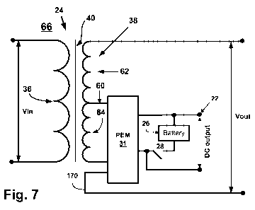
[0013] Fig. 7 shows a schematic circuit of a seventh hybrid transformer
constructed in accordance with a seventh embodiment of the present invention;
[0014] Fig. 8 shows a schematic circuit of an eighth hybrid transformer
constructed in accordance with an eighth embodiment of the present invention;
[0015] Fig. 9 shows a schematic circuit of a ninth hybrid transformer
constructed in accordance with a ninth embodiment of the present invention;
2
CA 02752816 2011-08-17
WO 2010/099459 PCT/US2010/025612
[0016] Fig. 10 shows a schematic circuit of a tenth hybrid transformer
constructed in accordance with a tenth embodiment of the present invention;
[0017] Fig. 11 shows a schematic circuit of a first power electronic module
(PEM) that may be used in the single phase hybrid transformers of the present
invention;
[0018] Fig. 12 shows a schematic circuit of a second PEM that may be used in
the single phase hybrid transformers of the present invention;
[0019] Fig. 13 shows a schematic circuit of a third PEM that may be used in
the single phase hybrid transformers of the present invention;
[0020] Fig. 14 shows a schematic circuit of a fourth PEM that may be used in
the single phase hybrid transformers of the present invention;
[0021] Fig. 15 shows a schematic circuit of a first filter that may be used in
the
first and second PEMs;
[0022] Fig. 16 shows a schematic circuit of a second filter that may be used
in
the third and fourth PEMs;
[0023] Fig. 17 shows a schematic circuit of a first protection device that may
be used in the first and second PEMs;
[0024] Fig. 18 shows a schematic circuit of a second protection device that
may be used in the third and fourth PEMs;
[0025] Fig. 19 shows a schematic of a sinusoidal waveform formed by pulse
width modulation;
[0026] Fig. 20 shows a schematic circuit of a hybrid transformer with an IED
and a communication link;
[0027] Fig. 21 shows a more detailed schematic circuit of a version of the
second hybrid transformer;
[0028] Fig. 22 shows a block diagram of a control scheme for a voltage
source inverter;
[0029] Fig. 23 shows a functional block diagram of a command trajectory
generation algorithm of the control scheme;
[0030] Fig. 24 shows a functional block diagram of a feedback control
algorithm of the control scheme;
[0031] Fig. 25 shows a feedforward control & disturbance input decoupling
algorithm of the control scheme;
3
CA 02752816 2011-08-17
WO 2010/099459 PCT/US2010/025612
[0032] Fig. 26 shows a state-space model of the control scheme;
[0033] Fig. 27 shows a simplified form of the state-space model;
[0034] Fig. 28 shows a plot of the input voltage of the simulated second
hybrid
transformer;
[0035] Fig. 29 shows a plot of the output (secondary) voltage of the simulated
second hybrid transformer;
[0036] Fig. 30 shows the regulation performance of the output voltage of a
voltage source converter of the simulated second hybrid transformer;
[0037] Fig. 31 shows a schematic of a three-phase hybrid transformer formed
from three single-phase hybrid transformers;
[0038] Fig. 32 shows a schematic circuit of a first three-phase hybrid
transformer;
[0039] Fig. 33 shows a schematic circuit of a voltage source converter of the
first three-phase hybrid transformer shown in Fig. 32;
[0040] Fig. 34 shows a schematic circuit of a second three-phase hybrid
transformer;
[0041] Fig. 35 shows a schematic circuit of a third three-phase hybrid
transformer;
[0042] Fig. 36 shows a schematic circuit of a voltage source converter of the
third three-phase hybrid transformer shown in Fig. 35;
[0043] Fig. 37 shows a schematic circuit of a fourth three-phase hybrid
transformer;
[0044] Fig. 38 shows a schematic circuit of a voltage source converter of the
fourth three-phase hybrid transformer shown in Fig. 37;
[0045] Fig. 39 shows a schematic circuit of a fifth three-phase hybrid
transformer;
[0046] Fig. 40 shows a schematic circuit of a voltage source converter of the
fifth three-phase hybrid transformer shown in Fig. 39;
[0047] Fig. 41 shows an application of a hybrid transformer of the present
invention for power factor correction;
[0048] Fig. 42 shows an application of a hybrid transformer of the present
invention for phase shifting and power-flow control on parallel lines; and
[0049] Fig. 43 shows an application of a hybrid transformer of the present
4
CA 02752816 2011-08-17
WO 2010/099459 PCT/US2010/025612
invention for a datacenter where AC and DC loads are powered by the hybrid
transformer.
DETAILED DESCRIPTION OF ILLUSTRATIVE EMBODIMENTS
[0050] It should be noted that in the detailed description that follows,
identical
components have the same reference numerals, regardless of whether they are
shown in different embodiments of the present invention. It should also be
noted
that in order to clearly and concisely disclose the present invention, the
drawings
may not necessarily be to scale and certain features of the invention may be
shown
in somewhat schematic form.
[0051] The present invention is directed to a hybrid transformer that may be
used
in the distribution of power. The hybrid transformer generally includes an
electromagnetic transformer that is integrated with a power electronic module
(PEM)
comprising a voltage source converter (VSC) that is operable to convert
between DC
and AC voltages, i.e., to convert DC voltage to AC voltage and vice versa. The
electromagnetic transformer includes a ferromagnetic core, a primary winding
structure and a secondary winding structure, each of which are wound on the
ferromagnetic core. The primary winding structure comprises one or more
primary
windings and the secondary winding structure comprises one or more secondary
windings. The PEM can be connected into the primary winding structure or the
secondary winding structure. The electromagnetic transformer may be a liquid-
filled
transformer, wherein the core and the primary and secondary winding structures
are
immersed in a dielectric fluid, or the electromagnetic transformer may be a
dry type
transformer, wherein the core and the primary and secondary winding structures
are
not immersed in a dielectric fluid, but, instead, are encased in a dielectric
resin or
surrounded by an inert gas, or simply ambient air. The hybrid transformer may
be a
single phase transformer, a three phase transformer, or a multiphase (> 3
phases)
transformer. The hybrid transformer may be pole-mounted or pad-mounted. A
single phase embodiment of the hybrid transformer may have a power rating of
about 67 kVA and a voltage rating of about 7.97 kV to 277 V.
[0052] Six embodiments of a hybrid distribution transformer constructed in
accordance with the present invention are shown in Figs. 1-5 and are
designated by
the reference numerals 10, 12, 14, 16, 18, 20, respectively. Each of the
hybrid
CA 02752816 2011-08-17
WO 2010/099459 PCT/US2010/025612
transformers 10-20 generally includes an electromagnetic transformer 24 and a
PEM
30. The electromagnetic transformer 24 has a single primary winding 36 and a
single
secondary winding 38 wound around a ferromagnetic core 40. The PEM 30
comprises a DC bus that can be used to power DC loads. The DC bus is connected
to DC output terminals 22 of the hybrid transformer 10-20. An energy storage
device, such as a battery bank 26, can be connected across the DC output
terminals
22 using a switch 28.
[0053] In the hybrid transformer 10 (shown in Fig. 1), the PEM 30 is connected
to
an end of the secondary winding 38. The voltage Vout across the secondary
winding
structure is equal to the voltage V1 across the secondary winding 38 plus the
voltage
V2 across the PEM 30. Since the output voltage equals the voltage output from
the
PEM 30 plus the voltage of the secondary winding 38, control of the voltage
output
from the PEM 30 controls the output voltage of the hybrid transformer 10.
[0054] In the hybrid transformer 12 (shown in Fig. 2), the PEM 30 is connected
to
an end of the primary winding 36. The voltage Vin across the primary winding
structure is equal to the voltage V1 across the primary winding 36 plus the
voltage
V2 across the PEM 30. Since the input voltage equals the voltage output from
the
PEM 30 plus the voltage of the primary winding 36, control of the voltage
output from
the PEM 30 controls the input voltage and, thus, the output voltage of the
hybrid
transformer 12.
[0055] The hybrid transformer 14 (shown in Fig. 3) has substantially the same
construction as the hybrid transformer 10, except a voltage divider 44 is
connected
into the secondary winding structure. The voltage divider 44 includes a pair
of series
connected resistors 46, 48 connected in parallel with the secondary winding 38
and
the PEM 30. An output of the voltage divider 44 is connected to a node in the
connection between the secondary winding 38 and the PEM 30. The resistances of
the resistors 46, 48 are selected to balance the voltage between the secondary
winding 38 and the PEM 30.
[0056] The hybrid transformer 16 (shown in Fig. 4) has substantially the same
construction as the hybrid transformer 12, except a voltage divider 52 is
connected
into the primary winding structure. The voltage divider 52 includes a pair of
series
connected resistors 54, 56 connected in parallel with the primary winding 36
and the
PEM 30. An output of the voltage divider 52 is connected to a node in the
6
CA 02752816 2011-08-17
WO 2010/099459 PCT/US2010/025612
connection between the primary winding 36 and the PEM 30. The resistances of
the
resistors 54, 56 are selected to balance the voltage between the primary
winding 36
and the PEM 30.
[0057] In the hybrid transformer 18 (shown in Fig. 5), the secondary winding
38
has one or more taps. Each tap is connected to a turn of the secondary winding
38,
between ends of the secondary winding 38. An inner tap 60 divides the
secondary
winding 38 into two winding portions 62 and 64. The winding portion 62 is
formed by
the inner tap 60 and a first extremity of the secondary winding 38 or,
alternately,
another, outer tap. Similarly, the winding portion 64 is formed by the inner
tap 60 and
a second extremity of the secondary winding 38 or, alternately, another, outer
tap.
The PEM 30 is connected in parallel to the winding portion 64 of the secondary
winding 38, with the inner tap 60 being connected to the line 152 of the PEM
30.
The voltage output Vout of the hybrid transformer 18 is equal to the voltage
across
the winding portion 62 only.
[0058] In the hybrid transformer 20 (shown in Fig. 6), the primary winding 36
has
one or more taps. Each tap is connected to a turn of the primary winding 36,
between ends of the primary winding 36. An inner tap 70 divides the primary
winding
36 into two winding portions 72 and 74. The winding portion 72 is formed by
the
inner tap 70 and a first extremity of the primary winding 36 or, alternately,
another,
outer tap. Similarly, the winding portion 74 is formed by the inner tap 70 and
a
second extremity of the primary winding 36 or, alternately, another, outer
tap. The
PEM 30 is connected in parallel to the winding portion 74 of the primary
winding 36,
with the inner tap 70 being connected to the line 152 of the PEM 30. The
voltage
across the winding portion 72 is equal to the voltage input to the hybrid
transformer
20, Vin.
[0059] A seventh embodiment of a hybrid transformer constructed in accordance
with the present invention is shown in Fig. 7 and is designated by the
reference
numeral 66. The hybrid transformer 66 has substantially the same construction
as
the hybrid transformer 18, except the hybrid transformer 66 has a PEM 31. In
addition, the PEM 31 is connected such that the output terminals of the hybrid
transformer 66 are connected to the first extremity of the secondary winding
38 (or
an outer tap) and an output line 170 from the PEM 31.
[0060] An eighth embodiment of a hybrid transformer constructed in accordance
7
CA 02752816 2011-08-17
WO 2010/099459 PCT/US2010/025612
with the present invention is shown in Fig. 8 and is designated by the
reference
numeral 68. The hybrid transformer 68 has substantially the same construction
as
the hybrid transformer 20, except the hybrid transformer 68 has a PEM 31. In
addition, the PEM 31 is connected such that the input terminals of the hybrid
transformer 68 are connected to the first extremity of the primary winding 36
(or an
outer tap) and the line 170 from the PEM 31.
[0061] A ninth embodiment of a hybrid transformer constructed in accordance
with the present invention is shown in Fig. 9 and is designated by the
reference
numeral 76. The hybrid transformer 76 includes an electromagnetic transformer
78,
which has a single primary winding 80 and a pair of secondary windings 82, 84
wound around a ferromagnetic core 86. The PEM 30 is connected to ends of the
secondary winding 84.
[0062] A tenth embodiment of a transformer constructed in accordance with the
present invention is shown in Fig. 10 and is designated by the reference
numeral 90.
The hybrid transformer 90 includes an electromagnetic transformer 92, which
has a
single secondary winding 94 and a pair of primary windings 96, 98 wound around
a
ferromagnetic core 100. The PEM 30 is connected to ends of the primary winding
98.
[0063] The PEM 30, 31 may have one of a plurality of different configurations.
Generally, however, the PEM 30, 31 comprises a VSC, a protection device, a
filter
and a control device. Two different configurations of the PEM 30 are shown in
Figs.
11 and 12 and are designated by the reference numerals 30a, 30b, respectively.
Two different configurations of the PEM 31 are shown in Figs. 13 and 14 and
are
designated by the reference numerals 31 a, 31 b, respectively.
[0064] Referring now to Fig. 11, the PEM 30a comprises a protection device
108,
a filter 110, a VSC 112 and a control device 114. The VSC 112 is a half bridge
inverter comprising a switching bridge 116 connected in parallel to a DC bus
120. A
DC voltage from the DC bus 120 is converted to a sinusoidal AC voltage by the
switching bridge 116. The switching bridge 116 includes a pair of switching
devices
122 connected in series. Each switching device 122 may be an insulated gate
bipolar transistor (IGBT) and an anti-parallel diode. The DC bus 120 includes
a pair
of capacitors 126, 128 connected in series. A first line 152 is connected to
the
switching bridge 116, between the switching devices 122 and a second line 154
is
8
CA 02752816 2011-08-17
WO 2010/099459 PCT/US2010/025612
connected to the DC bus 120 between the capacitors 126, 128. The protection
device 108 and the filter 110 are connected into the first and second lines
152, 154.
The control device 114 controls the operation of the switching devices 122.
The DC
bus 120 is connected to the DC output terminals 22 of the hybrid transformer.
[0065] Referring now to Fig. 12, the PEM 30b comprises a protection device
108,
a filter 110, a VSC 140 and a control device 114. VSC 140 is a full or H-
bridge
inverter comprising first and second switching bridges 142, 144 connected in
parallel
with a DC bus 146. A DC voltage from the DC bus 146 is converted to a
sinusoidal
AC voltage by the first and second switching bridges 142, 144. Each of the
first and
second switching bridges 142, 144 includes a pair of switching devices 148
connected in series. Each switching device 148 may be an insulated gate
bipolar
transistor (IGBT) and an anti-parallel diode. The DC bus 146 includes one or
more
capacitors 150. A first line 152 is connected to the first switching bridge
142 between
the switching devices 148 and a second line 154 is connected to the second
switching bridge 144 between the switching devices 148. The protection device
108
and the filter 110 are connected into the first and second lines 152, 154. The
control
device 114 controls the operation of the switching devices 148. The DC bus 146
is
connected to the DC output terminals 22 of the hybrid transformer.
[0066] It should be appreciated that the PEM 30a may be preferred for use in a
secondary winding structure, such as in hybrid transformers 10, 14, 18, while
the
PEM 30b may be preferred for use in a primary winding structure, such as in
hybrid
transformers 12, 16, 20. It should further be appreciated that other VSC
topologies
may utilized in lieu of the VSC 112 and the VSC 140.
[0067] Referring now to Fig. 13, the PEM 31 a is similar to the PEM 30b and
includes a protection device 109, a VSC 158, a filter 160 and a control device
114.
The VSC 158 has substantially the same construction as the VSC 140, except the
VSC 158 has a DC bus 162 with two capacitors 164, 166 and the second line 154
is
connected between the capacitors 164, 166. A third line 170 is connected to
the
second switching bridge 144 between the switching devices 148. The DC bus 162
is
connected to the DC output terminals 22 of the hybrid transformer. The
protection
device 109 and the filter 160 are connected into the first, second and third
lines 152,
154, 170.
[0068] Referring now to Fig. 14, the PEM 31 b includes a protection device
109, a
9
CA 02752816 2011-08-17
WO 2010/099459 PCT/US2010/025612
VSC 174, a filter 160 and a control device 114. The VSC 174 comprises first,
second and third switching legs 176, 178, 180 connected in parallel to a DC
bus
184. Each of the first, second and third switching legs 176-180 includes a
pair of
switching devices 186 connected in series. The control device 114 controls the
operation of the switching devices 186. Each switching device 186 may be an
insulated gate bipolar transistor (IGBT) and an anti-parallel diode. Other
components
and configurations, however, may be used for each switching device 186. For
example, a combination of parallel-connected switches (IGBT or otherwise) and
diodes may be used for each switching device 186. The DC bus 184 includes a
capacitor 188 and is connected to the DC output terminals 22 of the hybrid
transformer. DC voltage from the DC bus184 is converted to a sinusoidal AC
voltage by the first, second and third switching legs 176-180. The first line
152 is
connected through the protection device 109 and the filter 160 to the first
switching
leg 176 located between the switching devices 186. The second line 154 is
connected through the protection device 109 and the filter 160 to the second
switching leg 178 located between the switching devices 186. The third line
170 is
connected through the protection device 109 and the filter 160 to the third
switching
leg 180 located between the switching devices 186.
[0069] Referring now to Figs. 15 and 16, the filters 110, 160 help prevent
high
frequency harmonics from being introduced into the output voltage of the
hybrid
transformers 10-20, 66, 68, 76, 90 and the currents in the primary and
secondary
windings of their electromagnetic transformers as a result of the switching of
the
switching devices 122, 148, 186.
[0070] The filter 110 comprises an inductor 190 and a resistor 192 connected
in
series in the second line 154 and a capacitor 194 connected in parallel
between the
first and second lines 152, 154.
[0071] The filter 160 comprises inductors 200, 202, 204 connected into the
first,
second and third lines 152, 154, 170, respectively. A capacitor 208 is
connected in
parallel between the first and second lines 152, 154 and a capacitor 210 is
connected in parallel between the second and third lines 154, 170,
respectively.
[0072] It should be appreciated that the filters 110, 160 may have topologies
other than those shown and described.
[0073] Referring now to Figs. 17 and 18, the protection devices 108, 109 each
CA 02752816 2011-08-17
WO 2010/099459 PCT/US2010/025612
include a fault current limiting assembly that includes an impedance 214 and
an
electronic switch 216. The protection device 108 further includes two switches
218,
220 switches, whereas the protection device 110 further includes three
switches
218, 220, 222. Each of the switches 218-222 may be a mechanical switch, an
electronic switch or a hybrid mechanical/electronic switch. The switches 218-
222
and the electronic switch 216 are controlled by the control device 114.
[0074] The protection device 108 operates such that during normal operation of
the PEM 30 in the hybrid transformers 10-20, 76, 90, the switch 218 is closed
and
the switch 220 is open. If the PEM 30 malfunctions, a bypass can be created by
opening the switch 218 and closing the switch 220. During normal power network
operation, the electronic switch 216 is open and current flows through the PEM
30.
During a network phase-to-ground or phase-to-phase fault, the switch 218 is
opened
(while the switch 220 remains open) and the electronic switch 216 is closed,
thereby
forcing the fault current to pass through the impedance 214. By introducing
the
impedance 214 during faults, the fault current is limited to protect the
transformer
and upstream equipment. Impedance 214 can be of a resistive or an inductive
type.
[0075] The operation of the protection device 110 is similar to the operation
of the
protection device 108. During normal operation of the PEM 31 in the hybrid
transformers 66, 68, the switches 218, 222 are closed and the switch 220 is
open. If
the PEM 31 malfunctions, a bypass can be created by opening the switches 218,
222 and closing the switch 220. During normal power network operation, the
electronic switch 216 is open and current flows through the PEM 31. During a
network phase-to-ground or phase-to-phase fault, the switches 218, 222 are
opened
and the electronic switch 216 is closed, thereby forcing the fault current to
pass
through the impedance 214. By introducing the impedance 214 during faults, the
fault current is limited to protect the transformer and upstream equipment.
Impedance 214 can be of a resistive or an inductive type.
[0076] In addition to, or in lieu of, a protection device (108 or 109), the
control
device 114 of each hybrid transformer (10-20, 66, 68, 76 or 90) may control
the
switching devices of the VSC (112, 140, 158 or 174) to protect against short
circuit
faults. The control device 114 does so by monitoring the input voltage and the
output current of the hybrid transformer. If the output current exceeds a
predetermined limit, thereby indicating a short circuit fault in the output,
or the input
11
CA 02752816 2011-08-17
WO 2010/099459 PCT/US2010/025612
voltage drops below a certain level, thereby indicating a short circuit fault
in the
input, the control device 114 stops the pulse width modulation of all of the
switching
devices, i.e., turns off (opens) the switching devices.
[0077] In the hybrid transformers 12, 16, 20, 68 it is possible that the VSC
(112,
140, 158 or 174) may be subject to high voltage in the event of a short
circuit fault.
The control device 114 monitors the voltage across the VSC. If the VSC (140,
158 or
174) is used and the voltage increases above a predetermined level, thereby
indicating a fault, the control device 114 turns on (closes) the top two
switching
devices (or the bottom two switching devices) in the first and second
switching
bridges (while the other two switching devices are turned off), thereby
causing the
VSC to be bypassed.
[0078] In each PEM (30 or 31), the control device 114 includes a processor for
executing a program stored in associated memory that controls the VSC (112,
140,
158 or 174) using pulse width modulation (PWM), wherein the switching devices
(122, 148 or 186) are opened and closed to create a series of voltage pulses,
wherein the average voltage is the peak voltage times the duty cycle, i.e.,
the "on"
and "off" times of pulses. In this manner, a sine wave can be approximated
using a
series of variable-width positive and negative voltage pulses as shown in Fig.
19.
The phase and the amplitude of the sine wave can be changed by changing the
PWM pattern.
[0079] In each PEM (30 or 31), the control device 114 controls the switching
bridge(s) to balance the real power transferring from the VSC (112, 140, 158
or 174)
and to improve the primary side power factor by providing reactive power to
the load
through the transformer coupling. In addition, in each VSC (112, 140, 158 or
174),
the control device 114 maintains the output voltage of the hybrid transformer
at a set
value or reference output voltage (such as 240V RMS) and to be a clean
sinusoidal
waveform. Thus, in the event of a voltage sag, the control device 114
increases the
voltage output of the VSC (112, 140, 158 or 174) and in the event of a voltage
swell,
the control device 114 decreases the voltage output of the VSC (112, 140, 158
or
174).
[0080] In each of the hybrid transformers 10-20, 66, 68, 76, 90, the control
device
114 may be an intelligent electronic device (IED) or may interface with an
IED,
wherein the IED controls and monitors operational aspects of the hybrid
transformer
12
CA 02752816 2011-08-17
WO 2010/099459 PCT/US2010/025612
in addition to the VSC (112, 140, 158 or 174). Such an IED 260 is shown in
Fig. 20
mounted on or proximate to the hybrid transformer (10-20, 66, 68, 76 or 90).
The
IED 260 includes a user interface, a processor, memory and a communication
port.
In addition to controlling the VSC (112, 140, 158 or 174) and the devices
appurtenant thereto, the IED 260 monitors the operation of the hybrid
transformer
and communicates operating information to a remotely located control center
262
over a communication link 264, which may be may be a physical hardwired link,
a
satellite link, a cellular link, a modem or telephone line link, an Internet
link or any
other wireless or wide area or shared local area network link. For example,
the
currents, voltages and temperatures of the primary and/or secondary windings
may
be measured by sensors that are connected for communication with the IED 260.
The IED 260 may periodically or continuously transmit values for these
currents,
voltages and temperatures over the communication link 264 to the control
center
262 and/or may transmit alarms to the control center 262 over the
communication
link 264 if the values exceed certain predetermined limits. In addition to
transmitting
information about the primary and/or secondary windings, the IED 260 may
transmit
information about the operation of the VSC (112, 140, 158 or 174) to the
control
center 262 over the communication link 264. Moreover, the IED 260 may receive
and implement control commands from the control center 262 for changing the
operation of the VSC.
[0081] In addition to communicating with the control center 262, the IED 260
may
communicate with other IEDs. For example, the IED 260 may communicate with
other IEDs 260 installed in other hybrid transformers (10-20, 66, 68, 76 or
90) that
are part of the same power distribution network. The IEDs 260 may communicate
directly with each other or through a data server (not shown) located in the
control
center 262. In the former case, the IEDs 260 may communicate directly with
each
other via radio frequency transceivers, a wired or wireless local area network
(LAN)
or a communication bus. In the latter case, communication between each IED 260
and the data server occurs over the communication link 264.
[0082] The IED 260 may support the IEC61850 standard and, in so doing, define
abstract object models for electrical substations and a method for accessing
these
models over a network. The models can be mapped to a number of protocols,
including Manufacturing Message Specification (MMS), Generic Object Oriented
13
CA 02752816 2011-08-17
WO 2010/099459 PCT/US2010/025612
Substation Events (GOOSE), Generic Substation Status Event (GSSE), and
Sampled Measured Values (SMV). These protocols can run over TCP/IP networks
and/or LANs using high speed switched Ethernet.
[0083] Instead of using an IED to transmit operating information to a remotely
located control center, transmitters may be used to do so. The transmitters
may be
connected to the sensors and may transmit the values measured by the sensors
to a
remote location, such as the control center 262, via a communication link,
which
may be wireless, or hardwired.
[0084] In each of the hybrid transformers (10-20, 66, 68, 76 or 90), the DC
bus
(120, 146, 162 or 184) may be connected to provide DC power to the sensors,
transmitters and other communication devices that are used to monitor and
transmit
data concerning the operation of the hybrid transformer. The DC bus (120, 146,
162
or 184) may also be connected to provide DC power to the control device 114
and/or
IED 260. Depending on the application of the hybrid transformer, the DC bus
may
be connected to provide DC power to equipment associated with the application.
[0085] Referring now to Fig. 21, there is shown a more detailed view of an
embodiment of the hybrid transformer 12 (further designated by the letter "a")
containing electrical property labeling that will be used below to describe
the control
and operation of the hybrid transformer 1 2a. A positive end of the primary
winding
36 is connected by a line 270 to a voltage source 272 (providing a voltage
Vg), while
a negative end of the primary winding 36 is connected by a line 274 to the
voltage
source 272. In the embodiment shown in Fig. 21, the hybrid transformer 12a
utilizes
the VSC 30b and is connected into the primary winding structure by the low
pass
filter 110. The switching devices 148 are designated by reference descriptors
S, to
S4-
[0086] The VSC 30b in the hybrid transformer 12a may be controlled by the
control device 114 using a control scheme 278 shown in Figs. 22-26. The
control
scheme 278 includes a controller 280 and a state-space model ("model") 282 of
the
VSC 30b.
[0087] The controller 280 includes a command trajectory generation
("trajectory")
algorithm 284, a feedback control ("feedback") algorithm 286 and a feedforward
control & disturbance input decoupling (feedforward/decoupling) algorithm 288.
The
command trajectory of Vo* is generated as follows:
14
CA 02752816 2011-08-17
WO 2010/099459 PCT/US2010/025612
Vs error = Vs - Vs
Vo_preciamp = (Kp + 1 IS) x Vs
Vo fsat(Vo_preclamp)
where Vo_prec,amp is the voltage at the input of the saturation block in Fig.
23
For PWM, each of the first and second switching bridges 142, 144 of the VSC
30b
inverter is controlled separately by comparing Vtri with +Vret and - Vret. The
resulting
waveforms are used to control the switching devices 148 as follows:
if +Vret > Vtri S1 on, S2 Off
else, S1 Off, S2 on
if -Vret > Vtri S3 on, S4 Off
else, S3 Off, S4 on
where:
Vref is the voltage reference.
Vtri is the voltage of the triangular waveform used in the generation of the
PWM signal.
The controller 280 is a cascaded controller with an inner inductor current
loop and
an outer output voltage loop. The controller 280 uses state feedback
decoupling of
the equivalent series resistance (ESR) drop of the inductor 190. Nulling the
state
coupling in this approach allows a simple proportional gain, Ka, to be used in
forming the inductor current loop.
[0088] In Fig. 27, the model 282 (further designated by the letter "a") is
shown in
a simplified form. This simplification can be viewed as the input voltage
decoupling.
With this simplification, the open-loop transfer function of the physical
system
becomes:
VO(S) Kv
VL*(s) _ (L1. =s + esrL) -Co s
[0089] The transfer function of the command tracking is described as follows:
Vo Kp=Ka S+ Kj Ka
Vo* = L1-Co s3+ Co=Ka s2+ Kp Ka S+ Ki Ka
v
CA 02752816 2011-08-17
WO 2010/099459 PCT/US2010/025612
At low and mid frequencies, the command tracking is always Vc/Vc* = 1. At
intermediate high/mid and high frequencies, the command tracking becomes
Vc/Vc*
= 0. The closed-loop poles can be placed to the desired location by
determining
gains of Kp, K/, and Ka.
[0090] In order to enhance the control performance of the cascaded controller
format, the controller 280 additionally uses state command feedforward. At
low,
intermediate, and high frequencies, the command tracking is always Vc/Vc* = 1.
Therefore, desired AC voltage regulation is achieved with zero or nearly zero
steady-
state error in both magnitude and phase.
A A
L' =C s3 + Co. A Ka s 2 + KKa S+ Kt Ka
Vo K~ p
Vo* = L KC s3+ C =Ka s2+ Kp Ka S+ Ki Ka
v
[0091] A simulation of the hybrid transformer 12a with the controller 280 was
performed using Matlab Simulink. Control performance was investigated under
the
following simulation conditions:
Vg = 14400 V& 60Hz, Np/Ns = 120, Load = 1 + 11.885 S2 (5.2 + j=9.82 p.u) @60Hz
Cd = 60009F, Lf = 200,uH, esrLf = 50 mS2, Co = 40,uF
switching device 104 (IGBT) characteristics:
Vf = 2 V (IGBT voltage drop),
Tf= 1,us (IGBT fall time), Tt = 2,us (IGBT tail time),
Vd = 1 V (Diode voltage drop)
fpw,,, = 10kHz (Converter switching frequency)
Assumption: 1) Cd is pre-charged at 30% of Vg.
2) Only the magnitude of transformer secondary voltage is
regulated.
As shown in Fig. 28, in a transient period 290, a twenty percent (20%) sag is
first
introduced in the input voltage Vg. In a transient period 292, the input
voltage Vg is
then allowed to return to its normal value. Thereafter, in a transient period
294, a
twenty percent (20%) swell is introduced in the input voltage Vg. The input
voltage Vg
16
CA 02752816 2011-08-17
WO 2010/099459 PCT/US2010/025612
is again allowed to recover in a transient period 296. The results of these
changes
on the secondary voltage VS are shown in Fig. 29. For all of the transient
periods, the
hybrid transformer 12a shows very good magnitude regulation performance. Fig.
30
shows the regulation performance of the output voltage of the VSC 30b. Using
the
controller 280, very good AC voltage regulation is achieved. Ideally, the DC
bus
voltage (not shown) of the VSC 30b should keep constant, since the VSC 30b
provides only reactive power. However, in simulation, the switching devices
148
(IGBT) generate switching and conduction losses. Loss also happens at the
filter
inductor 190 due to ESR of the filter inductor 190. Thus, in sum, a voltage
droop in
the DC bus voltage occurs due to a combination of switching losses, conduction
losses, and losses from ESR of the filter inductor 190.
[0092] For each of the single-phase hybrid transformers 10-20, 66, 68, 76, 90,
three of the hybrid transformers can be combined to form a three-phase hybrid
transformer. A schematic of the connection is shown in Fig. 31. The primary
windings can be connected together in either a Delta configuration or a Wye
configuration, and the secondary windings can be connected together in either
a
Delta or a Wye configuration. With the three single phase hybrid transformers
connected together, no change is required to the control strategy. Each hybrid
transformer operates independent of the other two transformers. In Fig. 31,
for both
Delta and Wye configurations, u1 is connected to phase A (source), v1 is
connected
to phase B (source) and w1 is connected to phase C (source) and u2, v2 and w2
are
correspondingly connected on the load side. In the Delta configuration, u1' is
connected to phase B (source), v1' is connected to phase C (source) and w1' is
connected to phase A (source) and u2', v2' and w2' are correspondingly
connected
on the load side. In the Wye configuration, u1', v1' and w1' are connected to
neutral, N (source) and u2', v2' and w2' are correspondingly connected on the
load
side.
[0093] In lieu of having three separate PEMs (and VSCs) for a three phase
hybrid
transformer, a single integrated PEM (and VSC) may be provided for a three
phase
hybrid transformer. A three phase version of each of the single phase hybrid
transformers 10-20, 66, 68, 76, 90 may be provided with a single integrated
PEM
(and VSC). Examples of this are shown in Figs. 32-38.
[0094] Referring now to Fig. 32, there is shown a three-phase hybrid
17
CA 02752816 2011-08-17
WO 2010/099459 PCT/US2010/025612
transformer 300 that includes a three-phase electromagnetic transformer 302
and a
PEM 304. The hybrid transformer 300 is substantially a three phase version of
the
hybrid transformer 18 with a single integrated PEM (and VSC). The
electromagnetic
transformer 302 includes three primary windings 36a,b,c and three secondary
windings 38a,b,c mounted to a ferromagnetic core 306. The PEM 304 is shown in
Fig. 33 and includes a VSC with three switching legs 308, 310, 312 connected
in
parallel to a DC bus 316. Each of the switching legs 308-312 includes a pair
of
switching devices 318 connected in series. A control device 320 controls the
operation of the switching devices 318. Each switching device 318 may be an
insulated gate bipolar transistor (IGBT) and an anti-parallel diode. Other
components
and configurations, however, may be used for each switching device 318. For
example, a combination of parallel-connected switches (IGBT or otherwise) and
diodes may be used for each switching device 318. The DC bus 316 includes
capacitors 322, 324. DC voltage from the DC bus 316 is converted to sinusoidal
AC
voltages of different phases by the switching legs 308-312. A filter 328 is
connected
between the secondary windings 38 on one side and the switching legs 308-312
and
the DC bus 316 on the other side. Inner taps 60a,b,c are connected by lines
al, b1,
c1, respectively, to the neutral line N, which is connected to an output
bushing 330
and to the DC bus 316 of the PEM 304, between the capacitors 322, 324. In this
manner, the secondary windings 38 are connected in a Wye configuration. Ends
(or
outer taps) of the secondary windings 38 are connected by lines a2, b2, c2,
respectively, through the filter 328 to nodes of the switching legs 308-312,
wherein
each node is located between the switching devices 318. The filter 328 helps
prevent high frequency harmonics from being introduced into the output
voltages of
the transformer 300 and the currents in the primary and secondary windings 36,
38
as a result of the switching of the switching devices 318. The filter 328
comprises
inductors and optionally capacitors arranged in a manner similar to that in
the filter
160.
[0095] Although not shown, the PEM 304 may include a protection device having
a construction similar to the protection device 109 except adapted for a three
phase
application. It should also be appreciated that the PEM 304 could have a
fourth
switching leg and the neutral line could be connected to the fourth switching
leg,
between switching devices.
18
CA 02752816 2011-08-17
WO 2010/099459 PCT/US2010/025612
[0096] Although not shown a three-phase hybrid transformer may be provided
having the same construction as the three-phase hybrid transformer 300, except
the
PEM 304 is connected to the primary windings and taps therein. Such a
transformer
is substantially a three phase version of the hybrid transformer 20 with a
single
integrated PEM (and VSC).
[0097] Referring now to Fig. 34, there is shown a three-phase hybrid
transformer
301 that has substantially the same construction as the hybrid transformer
300,
except the hybrid transformer 301 does not have any taps connected to the PEM
304. The hybrid transformer 301 is substantially a three phase version of the
hybrid
transformer 10 with a single integrated PEM (and VSC).
[0098] Although not shown a three-phase hybrid transformer may be provided
having the same construction as the three-phase hybrid transformer 301, except
the
PEM 304 is connected to the primary windings therein. Such a transformer is
substantially a three phase version of the hybrid transformer 12 with a single
integrated PEM (and VSC).
[0099] Referring now to Fig. 35, there is shown a three-phase hybrid
transformer 340
that includes a three-phase electromagnetic transformer 302 and a PEM 342. The
hybrid transformer 340 is substantially a three phase version of the hybrid
transformer 66 with a single integrated PEM (and VSC). The electromagnetic
transformer 302 includes three primary windings 36a,b,c and three secondary
windings 38a,b,c mounted to a ferromagnetic core 306. The PEM 342 is shown in
Fig. 36 and includes seven switching legs 344, 346, 348, 350, 352, 354, 356
connected in parallel to a DC bus 358. Each of the switching legs 344-356
includes
a pair of switching devices 362 connected in series. A control device 370
controls
the operation of the switching devices 362. Each switching device 362 may be
an
insulated gate bipolar transistor (IGBT) and an anti-parallel diode. Other
components
and configurations, however, may be used for each switching device 362. For
example, a combination of parallel-connected switches (IGBT or otherwise) and
diodes may be used for each switching device 362. The DC bus 358 includes a
capacitor 364. DC voltage from the DC bus 358 is converted to sinusoidal AC
voltages of different phases by the switching legs 344-356. A filter 366 is
connected
between the secondary windings 38 on one side and the switching legs 344-356
and
the DC bus 358 on the other side. Lines al, b1, c1 connected through the
filter 366
19
CA 02752816 2011-08-17
WO 2010/099459 PCT/US2010/025612
connect the taps 60 on the secondary windings 38 to nodes of the switching
legs
346, 350, 354, respectively, wherein each node is located between the
switching
devices 362. Lines a2, b2, c2 connected through the filter 366 connect ends of
the
secondary windings 38 to nodes of the switching legs 348, 352, 356, wherein
each
node is located between the switching devices 362. Line N connects an output
bushing 368 to a node of the switching leg 344 located between the switching
devices 362. The output bushing 368 is adapted for connection to a neutral of
the
load. The filter 366 helps prevent high frequency harmonics from being
introduced
into the output voltages of the transformer 340 and the currents in the
primary and
secondary windings 36, 38 as a result of the switching of the switching
devices 362.
The filter 366 comprises inductors and optionally capacitors arranged in a
manner
similar to that in the filter 160, but for three phases.
[00100] Although not shown, the PEM 342 may include a protection device
having a construction similar to the protection device 109 except adapted for
a three
phase application.
[00101] The three-phase hybrid transformer 340 has the benefit of having only
seven switching legs. In the three-phase versatile transformer 340, the
switching
legs 344-356 for the three phases share a common DC bus 358. This arrangement
requires the switching legs 344-356 for the three phases to share a common
neutral
phase leg (line N), as shown. Line N is sized to carry a neutral current that
may be
greater than the individual phase currents (lines A, B, C). In addition, the
switching
devices 362 in the switching leg 344 should be constructed to carry the higher
current. The modulation indices of the switching legs 344-356 are different,
respectively, in order to maintain proper voltage differences between the
phase legs.
The voltage of the DC bus 358 is greater than the voltages in the DC buses
(162,
184) of the single phase VSCs 158, 174 in order to account for possible
imbalances.
[00102] Although not shown a three-phase hybrid transformer may be provided
having the same construction as the three-phase hybrid transformer 340, except
the
PEM 342 is connected to the primary windings and taps therein. Such a
transformer
is substantially a three phase version of the hybrid transformer 68 with a
single
integrated PEM (and VSC).
[00103] Referring now to Fig. 37, there is shown a three-phase hybrid
transformer 374 that includes a three-phase electromagnetic transformer 375
and a
CA 02752816 2011-08-17
WO 2010/099459 PCT/US2010/025612
PEM 376. The hybrid transformer 374 is substantially a three phase version of
the
hybrid transformer 76 with a single integrated PEM (and VSC). The
electromagnetic
transformer 375 includes three primary windings 80a,b,c, three main secondary
windings 82a,b,c and three auxiliary secondary windings 84a,b,c mounted to a
ferromagnetic core 377. For ease of illustration, the main secondary windings
82a,b,c are shown connected in a Wye configuration. It should be appreciated,
however, that the main secondary windings 82a,b,c may alternately be connected
in
a Delta configuration. The auxiliary secondary windings 84a,b,c may be
connected
in either a Wye or a Delta configuration, as indicated.
[00104] The PEM 376 is shown in Fig. 38 and includes a VSC 378 connected to
the auxiliary secondary windings 84, which may be connected in a Delta or Wye
configuration, as indicated. The VSC 378 has three switching legs 380, 381,
382 if
the auxiliary secondary windings 84 are connected in a Delta configuration. If
the
auxiliary secondary windings 84 are connected in a Wye configuration, a fourth
leg
384 may be further included. Each of the switching legs 380-384 includes a
pair of
switching devices 385 connected in series, each of which may be an insulated
gate
bipolar transistor (IGBT) and an anti-parallel diode. A control device 386
controls the
operation of the switching devices 385. The switching legs 380-384 are
connected in
parallel with a DC bus 387 that includes a capacitor 388. DC voltage from the
DC
bus 387 is converted to sinusoidal AC voltages of different phases by the
switching
legs. A filter 389 is connected between the auxiliary secondary windings 84
and the
VSC 78. The filter 389 helps prevent high frequency harmonics from being
introduced into the output voltages of the transformer 374 and the currents in
the
primary and secondary windings 80-84 as a result of the switching of the
switching
devices 385. The filter 389 comprises inductors and optionally capacitors
arranged
in a manner similar to that in the filter 160.
[00105] Although not shown, another three-phase hybrid transformer may be
provided that is substantially a three phase version of the hybrid transformer
90 with
a single integrated PEM (and VSC). In this transformer, the electromagnetic
transformer has three main primary windings, three auxiliary primary windings
and
three secondary windings mounted to a ferromagnetic core. This transformer may
utilize the PEM 376, except the PEM 376 is connected to the auxiliary primary
windings. The PEM 376 is connected to the auxiliary primary windings in the
same
21
CA 02752816 2011-08-17
WO 2010/099459 PCT/US2010/025612
manner as the PEM 376 is connected to the auxiliary secondary windings 84 in
the
hybrid transformer 374.
[00106] Referring now to Fig. 39, there is shown a three-phase hybrid
transformer
390 that includes a three-phase electromagnetic transformer 392 and a PEM 394.
The electromagnetic transformer 392 includes three primary windings 312a,b,c
for
connection to a voltage source. For each primary winding 312, there is a main
secondary winding 400 and an auxiliary secondary winding 402. The PEM 394 is
shown in Fig. 40 and includes a DC bus 404 connected in parallel between first
and
second bridges 406, 408. The first bridge 406 is connected to the auxiliary
secondary windings 402, which may be connected in a Delta or Wye
configuration,
as indicated. The first bridge 406 has three switching legs 412, 414, 416 if
the
auxiliary secondary windings 402 are connected in a Delta configuration. If
the
auxiliary secondary windings 402 are connected in a Wye configuration, a
fourth leg
418 is further included. The second bridge 408 has four switching legs 420,
422,
424, 426. Each of the switching legs 412-426 includes a pair of switching
devices
432 connected in series, each of which may be an insulated gate bipolar
transistor
(IGBT) and an anti-parallel diode. The DC bus 404 includes a capacitor 434.
[00107] A first filter 440 is connected between the auxiliary secondary
windings
402 on one side and the switching legs 412-418 on the other side. A second
filter
442 is connected between the switching legs 420-426 on one side and the main
secondary windings 400 and the neutral of the load on the other side. Lines
a1', b1',
c1' connected through the first filter 440 connect the auxiliary secondary
windings
402 to nodes of the switching legs 412-418, respectively, wherein each node is
located between the switching devices 432. Lines al, b1, c1 connected through
the
filter 442 connect the main secondary windings 400 to nodes of the switching
legs
422-426, wherein each node is located between the switching devices 432. Line
N
connects an output bushing 446 through the filter 442 to a node of the
switching leg
420 located between the switching devices 432. The output bushing 446 is
adapted
for connection to a neutral of the load. The first and second filters 440, 442
help
prevent high frequency harmonics from being introduced into the output
voltages of
the transformer 390 and the currents in the primary and secondary windings
312,
400, 402 as a result of the switching of the switching devices 432. The first
and
second filters 440, 442 each comprise inductors and optionally capacitors
arranged
22
CA 02752816 2011-08-17
WO 2010/099459 PCT/US2010/025612
in a manner similar to that in the filter 160, but for three phases.
[00108] A control device 450 controls the first bridge 406 to regulate the
voltage of the DC bus 404, while also optionally providing other features,
such as
providing harmonic filtering and improving the primary side power factor by
providing
reactive power to the load through the transformer coupling. The control
device 450
controls the second bridge 408 to maintain the output voltage of the
transformer 390
at a set value or reference output voltage and to be a clean sinusoidal
waveform.
Thus, in the event of a voltage sag, the control device 450 increases the
voltage
output of the PEM 394 and, in the event of a voltage swell, the control device
450
decreases the voltage output of the PEM 394.
[00109] Although not shown a three-phase hybrid transformer may be provided
having the same construction as the three-phase versatile transformer 390,
except
the transformer has main and auxiliary primary windings to which the PEM 394
is
connected.
[00110] In the three phase hybrid transformers described above, the control
device(s) may be an intelligent electronic device (IED) or may interface with
an IED,
wherein the IED controls and monitors operational aspects of the hybrid
transformer
in addition to the VSC(s). Such an IED may be substantially similar to and
operate in
substantially the same manner as the IED 260 described above.
[00111] The hybrid transformer of the present invention provides a number of
benefits. The PEM is operable to control the power factor on the primary side
of the
hybrid transformer. In contrast, the power factor on the primary side of a
conventional transformer depends on the load. In addition, the PEM is operable
to
reduce fluctuation in the output voltage of the hybrid transformer in the
event of a
sag or a swell in the input voltage. The input current of the hybrid
transformer is also
smaller than that of a conventional transformer because the hybrid transformer
generates all the needed reactive power and, thus, the voltage source only
provides
the real power to the load. The hybrid transformer may be used in datacenters,
naval
propulsion systems, automotive manufacturing facilities, pharmaceutical
plants,
hospitals, polymer processing plants, paper mills and wind farms.
[00112] In Fig. 41(a), a conventional power system 550 for power factor
correction is shown. The power system 550 includes a conventional
electromagnetic
transformer 560, and a switchable capacitor bank 570. The capacitor bank 570
is
23
CA 02752816 2011-08-17
WO 2010/099459 PCT/US2010/025612
switched by incremental steps to provide reactive power needed for load power
factor correction. This method is characterized by a slow response and a large
footprint. The hybrid transformer (10-20, 66, 68, 76 or 90) shown in Fig.
41(b)
provides a continuous and fast change of reactive power output needed for
power
factor correction. It provides an integrated solution that requires less
capacitor rating
and a limited footprint.
[00113] In Fig. 42, a power system 600 connecting two networks 610 and 620
using two parallel lines 630 and 640. In practice, the parallel lines do not
have the
same impedance and the power flowing in one line is greater that that flowing
in the
other line. Under heavy load condition, one of the lines 630, 640 may be
subjected
to thermal overload, thereby causing line sags and mechanical stresses. When
the
hybrid transformer (10-20, 66, 68, 76 or 90) is placed in series with the line
630, it
allows control of power flow through line 630 by imposing a phase shift on the
output
voltage. The hybrid transformer (10-20, 66, 68, 76 or 90) can be placed in
series
with both of the lines 630 and 640 and control the power flow on that
corridor.
[00114] In Fig. 43(a), a conventional power system 700 for a data center is
shown. The power system 700 includes a conventional electromagnetic
transformer
702, a conventional uninterruptible power supply (UPS) 704, a battery bank 706
and
a rectifier 708. The UPS 704 and the transformer 702 are connected to an AC
voltage source and provide conditioned AC power to AC loads. The UPS 704 is
connected to the battery bank 706 to provide AC power in the event of a
failure of
the voltage source. The rectifier 708 converts the conditioned AC power to DC
power that is used to power DC loads, such as computers.
[00115] The conventional power system 700 can be replaced by the hybrid
transformer (10-20, 66, 68, 76 or 90) having the battery bank 26 connected
across
the DC output terminals 22 of the hybrid transformer through the switch 28. As
shown in Fig. 43(b), the DC loads are connected to the DC output terminals of
the
hybrid transformer (10-20, 66, 68, 76 or 90). Under normal conditions, the
battery
bank 26 is maintained at full charge, but the switch 28 is open. DC power is
provided
to the DC loads from the PEM (30 or 31). Upon the occurrence of a power
outage,
the switch 28 closes and DC power is supplied from the battery bank 26 to the
DC
loads until AC power is restored or a local generator unit is started.
[00116] The hybrid transformer (10-20, 66, 68, 76 or 90) with the battery bank
24
CA 02752816 2011-08-17
WO 2010/099459 PCT/US2010/025612
26 provides the same benefits as the conventional power system 700, but more
efficiently and with less equipment.
[00117] As will be appreciated by one of skill in the art and as before
mentioned, the present invention may be embodied as or take the form of the
methods of controlling and monitoring hybrid transformers previously
described, a
computing device or system having program code configured to carry out the
methods, a computer program product on a computer-usable or computer-readable
medium having computer-usable program code embodied in the medium. The
computer-usable or computer-readable medium may be any medium that can
contain, store, communicate, propagate, or transport the program for use by or
in
connection with the instruction execution system, apparatus, or device and may
by
way of example but without limitation, be an electronic, magnetic, optical,
electromagnetic, infrared, or semiconductor system, apparatus, device, or
propagation medium or even be paper or other suitable medium upon which the
program is printed. More specific examples (a non-exhaustive list) of the
computer-
readable medium would include: a portable computer diskette, a hard disk, a
random access memory (RAM), a read-only memory (ROM), an erasable
programmable read-only memory (EPROM or Flash memory), an optical fiber, a
portable compact disc read-only memory (CD-ROM), an optical storage device, a
transmission media such as those supporting the Internet or an intranet, or a
magnetic storage device. Computer program code or instructions for carrying
out
operations of the present invention may be written in any suitable programming
language provided it allows to achieve the previously described technical
results.
The program code may execute entirely on the user's computing device, partly
on
the user's computing device, as a stand-alone software package, partly on the
user's
computer and partly on a remote computer or entirely on the remote computer or
server. In the latter scenario, the remote computer may be connected to the
user's
computer through a local area network (LAN) or a wide area network (WAN), or
the
connection may be made to an external computer (for example, through the
Internet
using an Internet Service Provider).
[00118] It is to be understood that the description of the foregoing exemplary
embodiment(s) is (are) intended to be only illustrative, rather than
exhaustive, of the
present invention. Those of ordinary skill will be able to make certain
additions,
CA 02752816 2011-08-17
WO 2010/099459 PCT/US2010/025612
deletions, and/or modifications to the embodiment(s) of the disclosed subject
matter
without departing from the spirit of the invention or its scope, as defined by
the
appended claims.
26