Note : Les descriptions sont présentées dans la langue officielle dans laquelle elles ont été soumises.
CA 02754661 2011-08-29
1
DESCRIPTION
A set of members for an evaporative pattern and an evaporative pattern
Technical Field
[0001] The present invention relates to an evaporative pattern that is used in
full-mold casting,
and a set of members that form the evaporative pattern.
Background Art
[0002] Full-mold casting is one known method of forming metal products. In
full-mold casting,
a pattern is prepared that has the same shape as the metal product to be
formed. The pattern is
formed from a material that evaporates when it comes into contact with molten
metal. When the
evaporative pattern is packed inside a sand mold and molten metal is poured
into the sand mold,
the pattern will evaporate and be replaced with the molten metal. When the
sand mold is
destroyed after the molten metal has cooled, a cast product having the same
shape as the pattern
will be obtained.
[0003] Although full-mold casting is an excellent method for forming metal
products having
complex shapes, one problem is that it is difficult to fill the powder
material that forms the sand
mold around the evaporative pattern. In general, metal molds have complex
shapes, therefore,
the evaporative patterns for the metal molds have complex shapes. Cavities are
easily formed
around an evaporative pattern having a complex shape (i.e., spaces that are
not filled with the
powder material are left around the evaporative pattern) when the evaporative
pattern is packed
in a sand mold. Thus, difficult work will need to be continued over a long
period of time in order
to form a good sand mold.
[0004] A standard metal mold is formed by machining a metal blank, and
comprises a mold
surface that comes into contact with a work piece, and a positioning surface
that contacts the
other side of the metal mold and adjusts the positional relationship with the
other side of the
metal mold. The metal blank on the back sides of the mold surface and the
positioning surface
plays a role in providing the mold surface, providing the positioning surface,
and fixing the
relative positional relationship between the mold surface and the positioning
surface. Here, the
portion that fixes the relative positional relationship between the mold
surface and the
positioning surface need not be a metal blank.
CA 02754661 2011-08-29
2
[0005] Patent Reference 1 discloses a metal mold that reinforces the lower die
made of a plate
with a lower frame, and reinforces the upper die made of a plate with an upper
frame. The upper
frame and lower frame used here are comprised of a plurality of bar-shaped
members, as well as
a three-dimensional mesh structure having connecting points that link the ends
of the bar-shaped
members and are distributed inside a three-dimensional space. By using a three-
dimensional
mesh structure instead of a metal blank, a product capable of being used as a
metal mold can be
achieved.
Prior Art Reference
Patent Reference
[0006] Patent Reference 1: Japan Published Unexamined Patent Application No. 7-
323400
[0007] With a metal mold having a portion of the metal blank replaced with a
three-
dimensional mesh structure, the task of filling the powder material around the
evaporative
pattern for forming the metal mold will be simplified. A metal mold in which a
portion thereof is
replaced with a three-dimensional mesh structure will be easy to form with
full-mold casting. In
addition, a metal mold in which a portion thereof is replaced with a three-
dimensional mesh
structure will also have advantages, such as being lightweight, the rigidity
thereof can be easily
adjusted, and the heat radiation characteristics thereof can be easily
adjusted. The present
inventors have discovered the advantages of a metal mold in which a portion
thereof is replaced
with a three-dimensional mesh structure, have discovered the good
compatibility between that
metal mold and full-mold casting, and are conducting research on technology
for forming that
metal mold by means of full-mold casting in which a portion of the evaporative
pattern is
replaced with a three-dimensional mesh structure.
Summary of Invention
Technical Problem
[0008] As a result of this research, it became clear that technology for
simplifying the process
of forming an evaporative pattern was needed. Three-dimensional mesh
structures are not only
those formed by repeating units of structure at regular intervals, but also
include mesh structures
in which the angles between the plurality of bar-shaped members are changed
depending on
location. In order to realize this type of mesh structure, the angles between
the bar-shaped
members must be freely adjusted during the task of connecting the bar-shaped
members.
CA 02754661 2011-08-29
3
[0009] A set of members which achieves a three-dimensional mesh structure by
connecting the
ends of the bar-shaped members is known. For example, building block sets are
known which
are constructed from a plurality of bar-shaped members and a plurality of
connecting members.
As illustrated in Fig. 10, when the connecting member 40b is a regular
hexahedron, a hole is
formed in each of the six sides for inserting the ends of bar-shaped members
40a1 - 40a6. If this
set of building blocks is used, 12 bar-shaped members can be fixed on the 12
edges that form a
cube by using 12 bar-shaped members and 4 connecting members. If this set of
building blocks
is used, cubes can form units, and a three-dimensional mesh structure can be
formed by
combining a plurality of cube units. Fig. 9 illustrates another example of bar-
shaped members
and connecting members, in which tubular bar-shaped members can be used to
form a three-
dimensional mesh structure. In addition, sets of members used for building
crystalline structures
such as hexagonal crystals, steric structures such as organic molecules, or
the helical structure of
DNA are also known.
[0010] However, with prior art sets of members, the angle between the bar-
shaped members is
limited to a predetermined angle, and thus the angle between the bar-shaped
members cannot be
freely adjusted to a desired angle. As shown in Fig. 10, when the connecting
members are cubes,
the angles between the bar-shaped members are limited to 90 degrees or 180
degrees, and cannot
be placed in other angles. In the case of Fig. 9, by adjusting the direction
at which the receiving
portions extend in a straight line from the center of the connecting member,
the angle between
the bar-shaped members can be established. However, because the angle between
the bar-shaped
members is established by the direction in which the receiving portions
extend, it cannot be
adjusted to another angle.
[0011] The present invention relates to a set of members for assembling an
evaporative pattern
to be used in a full-mold casting, and provides a set of members that can
freely adjust and fix the
angle between bar-shaped members.
Solution to Technical Problem
[0012] The present invention provides a set of members comprising a plurality
of bar-shaped
members formed of an evaporative material, and a plurality of connecting
members formed of an
evaporative material. Each of the connecting members has a substantially
spherical shape.
Because of this, the ends of a plurality of the bar-shaped members can be
fixed to one connecting
member. The ends of the plurality of bar-shaped members can be connected by
the connecting
CA 02754661 2011-08-29
4
member, and a three-dimensional mesh structure can be achieved. Moreover, the
fixing angle of
each bar-shaped member with respect to the connecting member can be adjusted
freely. The
angle between the bar-shaped members can be freely adjusted and fixed. A mesh
structure can be
achieved in which the angle between the bar-shaped members changes according
to location. A
set of members that can achieve a mesh structure of various shapes will be
obtained.
[0013] It is preferable that projections that lodge in the connecting member
be formed on the
end of each bar-shaped member. By lodging projections formed in the ends of
the bar-shaped
members into the connecting member, the fixing angle of the bar-shaped members
with respect
to the connecting member, and the angle between the bar-shaped members, can be
maintained at
the desired angle. When the connecting member is fixed with adhesive or the
like to the bar-
shaped members, the adjusted angle can be prevented from slipping.
[0014] When the aforementioned set of members is used, an evaporative pattern
can be
constructed of a plurality of bar-shaped members formed with an evaporative
material and a
plurality of connecting members formed with an evaporative material, the end
portions of the
plurality of bar-shaped members being fixed to one connecting member to form a
three-
dimensional mesh structure, and each connecting member having an almost
spherical shape.
Although there are cases in which the entire evaporative pattern is formed
with the
aforementioned set of members, there may also be cases in which the entire
evaporative pattern
is completed by adding other members to this set.
Brief Description of Drawings
[0015] Fig. 1 shows a perspective view of a portion of an evaporative pattern
used in full-mold
casting.
Fig. 2 shows a metal mold set into a press. A part of the metal mold is formed
with a
three-dimensional mesh structure.
Fig. 3 shows the ends of a plurality of bar-shaped members fixed to a
connecting
member having a spherical shape.
Fig. 4 shows a first example of a connecting member having a spherical shape
and the
shape of the end of a bar-shaped member.
Fig. 5 shows a second example of a connecting member having a spherical shape
and
the shape of the end of a bar-shaped member.
CA 02754661 2011-08-29
Fig. 6 shows a third example of a connecting member having a spherical shape
and the
shape of the end of a bar-shaped member.
Fig. 7A shows a fourth example of a spherically shaped connecting member prior
to
being fixed to a bar-shaped member.
5 Fig. 7B shows the fourth example of a spherically shaped connecting member
after
being fixed to a bar-shaped member.
Fig. 8A shows a fifth example of a spherically shaped connecting member prior
to being
fixed to bar-shaped members.
Fig. 8B shows the fifth example of a spherically shaped connecting member
after being
fixed to bar-shaped members.
Fig. 9 shows a first example of a conventional connecting member and bar-
shaped
members.
Fig. 10 shows a second example of a conventional connecting member and bar-
shaped
members.
Description of Embodiments
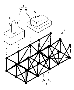
[0016] Fig. 1 shows a perspective view of a portion of an evaporative pattern
2 in which a
portion thereof is formed with a three-dimensional mesh structure 6. Fig. 1
shows blocks 4a, 4b
separated from the three-dimensional structure 6, but in fact the blocks 4a,
4b are fixed to the
three-dimensional mesh structure 6, and the relative positional relationship
of the blocks 4a, 4b is
fixed in a defined positional relationship by the three-dimensional mesh
structure 6. In addition,
blocks 4c, 4d, etc. may also be fixed to the three-dimensional structure 6.
[0017] The three-dimensional mesh structure 6 is formed by assembling together
a plurality of
bar-shaped members 6a and a plurality of connecting members 6b. Each of the
bar-shaped
members 6a is formed from a material that evaporates when it comes into
contact with molten
metal, e.g., polystyrene foam, paper, or the like. Each of the bar-shaped
members 6a may be
hollow (i.e., tubular), or may be solid. Both ends of the tube may be closed
with an evaporative
cap. Each of the connecting members 6b is formed from a material that
evaporates when it
comes into contact with molten metal, e.g., polystyrene foam, paper, or the
like. Each of the
connecting members 6b may be hollow, or may be solid. As shown in Fig. 1, the
ends of the
plurality of bar-shaped members 6a are fixed to one connecting member 6b.
Adjacent bar-shaped
members are fixed together via a connecting member. The angle between bar-
shaped members is
regulated by the fixing angle of the bar-shaped members with respect to the
connecting member.
CA 02754661 2011-08-29
6
[0018] The blocks 4a, 4b are formed by machining a block of polystyrene foam.
With the
present embodiment, a machined surface 10 is formed on the block 4b, a guide
pin 8 is formed
on the block 4a, and a positioning hole in which the guide pin 8 is inserted
is formed in a block
4c that is not illustrated. The block 4a, 4b (and the block 4c not
illustrated) are adhered to the
three-dimensional structure by means of an adhesive. In Fig. 1, although the
blocks 4a, 4b, etc.
are adhered to the connecting member 6b, they may be adhered to the bar-shaped
members 6a.
[0019] An actual mesh structure 6, as shown in Fig. 1, may have some of the
bar-shaped
members removed, or may have additions added to some of the bar-shaped
members. The three-
dimensional structure 6 will be a truss structure or a Rahman structure. It
may also have a
mixture of truss and Rahman structures. The arranged positions of the
connecting member 6b
need not be uniformly distributed, and if some positions are arranged densely,
then other
positions will be arranged sparsely. In other words, the angle between bar-
shaped members will
differ depending on location. Note that the bar-shaped members are not
necessarily straight, and
curved bar-shaped members may also be used.
[0020] When the evaporative pattern 2 is used to perform full-mold casting, a
cast product will
be obtained that has the same shape as the evaporative pattern. 2. In the
present embodiment, this
cast product is used in as metal mold 3 for pressing. In the present
embodiment, the bar-shaped
parts are distinct from the bar-shaped members. The bar-shaped parts are
portions that form a
part of a large object and have a bar shape. The bar-shaped members are
independent members
that are bar-shaped. The relationship between connecting parts and connecting,
members,
between block parts and block members, and between tubular part and tubular
members are
same. The evaporative pattern has bar-shaped members and connecting members.
The cast
product is integral, therefore, has bar-shaped parts and connecting parts. In
the cast product,
there are no longer members.
[0021 ] Fig. 2 shows a metal mold 3 for pressing that was cast by full-mold
casting and fixed to
a bolster 70 of a press 78, and a metal mold 53 for pressing that was also
cast by the full-mold
casting and fixed to a slider 72 of the press 78. Note that 74 in the drawing
is a slide guide for the
press 78, and 76 is an actuator for the press 78. When the actuator 76
operates, the slider 72
drops downward along the slide guide 74. When this occurs, the guide pin 8 of
the metal mold 3
will be inserted into a positioning hole 8a of the metal mold 53, a guide pin
58 of the metal mold
53 will be inserted into a positioning hole 58a of the metal mold 3, and the
relative positional
relationship between the metal mold 3 and the metal mold 53 will be positioned
in a prescribed
positional relationship. The block 4a, the guide pin 8, the block 4b, the
machined surface 10, etc.
of Fig. 1 are portions of the evaporative pattern, and formed with polystyrene
foam. In contrast,
CA 02754661 2011-08-29
7
the block 4a, the guide pin 8, the block 4b, the machined surface 10, etc. of
Fig. 3 are portions of
the metal mold 3, and formed with cast metal. Although the same reference
numerals are used
for the sake of convenience, they are in fact different members. Because they
are shown as
having the same shape, the same reference numerals are used for the sake of
convenience.
[0022] In the metal mold 3, the blocks 4a, 4c are fixed with respect to the
block 4b by means of
the mesh structure 6. Likewise in the metal mold 53, the blocks 54a, 54c are
fixed with respect to
the block 54b by means of a mesh structure 56. If the block 4a and the block
54a are positioned
in a prescribed positional relationship, and the block 4c and the block 54c
are positioned in a
prescribed positional relationship, the block 4b and the block 54b will also
be positioned in a
prescribed positional relationship. As a result, the machined surface 10 of
the metal mold 3 and a
machined surface 60 of the metal mold 53 will also be positioned in a
prescribed positional
relationship. When the slider 72 drops down, the work piece W will be
sandwiched between the
machined surface 10 of the metal mold 3 and the machined surface 60 of the
metal mold 53, and
will be pressed into a prescribed shape.
[0023] The metal mold 3 comprises a structure in which the blocks 4a, 4c for
positioning and
the block 4b for machining are fixed to the three-dimensional mesh structure
6. The metal mold
3 is lightweight because the portion that fixes the positional relationship of
the blocks is the
three-dimensional mesh structure 6 and not a metal block. In addition, the
blocks can be
connected with an appropriate amount of rigidity because the positional
relationship of the
blocks is prescribed by the three-dimensional mesh structure 6. For example,
the rigidity
between the blocks can be adjusted to be stiff such that when the block 4a and
the block 54a are
positioned in a prescribed positional relationship, and the block 4c and the
block 54c are
positioned in a prescribed positional relationship, the block 4b and the block
54b are also
positioned in a prescribed positional relationship. At the same time, the
rigidity between the
blocks can be adjusted to be flexible such that when the machined surface 10
of the block 4b and
the machined surface 60 of the block 54b are slightly tilted at the prescribed
positional
relationship and a localized range of the machined surface 10 and the machined
surface 60 press
strongly on the work piece W, the block 4b and the block 54b can be rotated
relative to each
other due to the localized reaction force and the machined surface 10 and the
machined surface
60 uniformly press on the work piece W.
[0024] In addition, the evaporative pattern 2 comprising the blocks 4a, 4b, 4c
and the mesh
structure 6 can be easily packed in a sand mold, and it will be difficult for
spaces to remain
around it. It has good compatibility with full-mold casting. The task of
packing sand around the
evaporative pattern 2 can be performed relatively easily and completed in a
short period of time,
CA 02754661 2011-08-29
8
and a good quality sand mold can be obtained which is filled with powder
material around the
evaporative pattern 2 without gaps and with a uniform density. Details on and
advantages of full-
mold casting performed by using an evaporative pattern constructed of a
plurality of blocks and a
three-dimensional mesh structure are disclosed in the specification and
drawings of Japan Patent
Application No. 2010-112533. Note that redundant disclosure therefrom has been
omitted.
[0025] Fig. 3 shows an enlargement of the area around the ends of the
plurality of bar-shaped
members 6a1-6a4 that connect to the connecting member 6b. The connecting
member 6b has a
size that allows the end surfaces of a plurality of bar-shaped members to be
fixed thereto. In
addition, the connecting member 6b is formed into a substantially spherical
shape, and the bar-
shaped members can be fixed thereto at any angle. Thus, for example the angle
between the bar-
shaped members 6a1 and 6a2 can be set to any angle, and that angle can be
fixed.
[0026] Fig. 4 shows an example of the shape of the end of the bar-shaped
members 6a that
connects to the connecting member 6b. The bar-shaped member 6a may have a
straight bar shape
and an end surface that comports with the connecting member 6b.
Fig. 5 shows an example in which the bar-shaped member 6a are formed with a
straight
central portion 14 and an end portion 16 that expands toward the connecting
member 6b. When
comprised of an end portion 16 that expands toward the connecting member 6b,
the adhesive
strength between the bar-shaped members 6a and the connecting member 6b will
be increased,
and the concentration of stress can be mitigated.
Fig. 6 shows an example of a space that is preserved between the end surface
of the end
portion 20 and the spherically shaped connecting member 6b. This space can be
used to allow an
adhesive to harden. When the end surfaces of the bar-shaped members 6a are
formed into a
shape in which the bar-shaped members 6a are in direct contact with and fixed
to the connecting
member 6b, the positional relationship between the bar-shaped members 6a and
the connecting
member 6b can be stabilized after being adhered, and an evaporative pattern
having a high
degree of precision can be formed.
Fig. 7 shows an example in which projections 22, 24 are formed on the end of
the end
portion 16 of Fig. 5. As shown in Fig. 7B, the projections 22, 24 and the
connecting member 6b
are formed with a material and shape so that the projections 22, 24 will lodge
into the connecting
member 6b when the ends of the bar-shaped members 6a are pushed into the
connecting member
6b. When the projections 22, 24 are lodged into the connecting member 6b in a
state in which the
fixing angle of the bar-shaped members 6a, with respect to the connecting
member 6b, and the
angles between the bar-shaped members are adjusted to the desired angles,
slippage from the
CA 02754661 2011-08-29
9
adjusted angles can be prevented while the adhesive that adheres the
connecting member to the
bar-shaped members hardens.
Fig. 8 shows an example of the outer surface of the end portion 16 formed into
a partial
spherical shape. Although it cannot be formed into a completely spherical
shape in this situation,
it can be formed into a shape that resembles a sphere. When the outer surface
of the end portion
16 is formed into a quasi-spherical shape, another bar-shaped member can be
fixed to the outer
side thereof. A small relationship between the angles of the bar-shaped
members can be obtained
while using the end portion to increase the adhesive strength between the bar-
shaped members
and the connecting member.
[0027] In the present embodiments, the connecting member 6b is formed with a
solid piece of
polystyrene foam. The bar-shaped members 6a can also be formed with a solid
piece of
polystyrene. In the alternative, the bar-shaped members 6a may be formed with
a paper pipe. In
the present embodiments, both ends of the paper pipe are closed with
polystyrene caps. When an
evaporative pattern having a paper pipe is used to perform full-mold casting,
the paper pipe will
be carbonized by the heat of the molten metal, and when the cast metal product
is taken out of
the sand mold, the carbonized paper pipe will be removed. Instead of a paper
tube that
evaporates, a tube member that does not evaporate may also be used. For
example, a tube
member produced from steel used in metal molds may be used. In this situation,
the tube
member will remain even after full-mold casting has been performed, and a
composite cast
product filled with solidified cast metal in the interior thereof will be
obtained. A composite cast
product can also be obtained in which the quality of the material changes
depending on the site.
When non-evaporative tube members are used in regions in which a pattern is
formed, gas will
not be generated when the pattern evaporates, and molten metal will easily
pass through the
interior of the tube members. When an evaporative tube member is replaced with
a non-
evaporative one, the quality of the cast metal product can be prevented from
declining.
[0028] Specific embodiments of the present invention are described above, but
are mere
illustrations and do not restrict the claims. The art set forth in the claims
includes variations and
modifications of the specific examples set forth above. The technological
components described
in the present specification or the drawings exhibit technological utility
individually or in various
combinations, and are not limited to the combinations disclosed in the claims
at the time of
application. In addition, the technology illustrated in the present
specification or the drawings
simultaneously achieve a plurality of objects, and achieving one object from
amongst these has
technological utility in and of itself.
CA 02754661 2011-08-29
Reference Signs List
[0029] 2: Evaporative pattern
4: Block
6: Three-dimensional mesh structure
5 6a: Bar-shaped member
6b: Connecting member
8: Guide pin
10: Machined surface