Note : Les descriptions sont présentées dans la langue officielle dans laquelle elles ont été soumises.
CA 02755184 2016-10-03
10-mPCS-244(PDA)
- 1 -
ACOUSTIC SENSOR SYSTEM FOR DETECTING ELECTRICAL
CONDUCTIVITY FAULTS IN AN ELECTRICAL DISTRIBUTION SYSTEM
BACKGROUND
Field
The disclosed concept pertains generally to acoustic noise induced by
electrical conductivity faults and, more particularly, to acoustic sensor
systems for
electrical distribution systems.
Background Information
There is no known cost effective technology and product to detect
loose electrical connections in electrical distribution systems. An infrared
imaging
scan has been widely used to find such loose electrical connections, but this
does not
provide continuous (e.g., "24-7" or 24 hours a day, seven days a week)
detection and
monitoring, is limited to detecting only joints within view, and exposes the
operator to
potentially hazardous conditions.
Other known products employ temperature sensing at each electrical
joint. However, this has not been widely adopted due to cost.
It is believed to be almost impossible to extract a loose electrical
connection signature from both current and voltage due to the relatively small
voltage
drop across a loose electrical connection (except when this escalates into a
major arc
CA 02755184 2011-10-18
I 0-mPCS-244(PDA)
- 2 -
fault or arc flash event) except by monitoring voltage drops at each
electrical
connection.
U.S. Patent No. 7,148,696 discloses that an acoustic signature is
generated by an arc fault or a glowing contact. An acoustic sensor "listens"
directly
to signature noise generated by a fault, no matter what type of electrical
load is
present or in what kind of environment in which the fault is generated. The
acoustic
noise generated by an arc fault or a glowing contact has an acoustic signal at
one or
more specific wavelengths that is (are) directly related to either the basic
characteristics of, for example, the arc and its resonance frequency or the AC
power
source modulated frequency and its harmonics. The acoustic signal of an arc
fault is
detected by an acoustic sensor. A resulting trip signal is sent to a trip
mechanism to,
for example, trip open separable contacts, in order to interrupt the arc
fault.
There is a need for a cost effective technology and product to
effectively detect electrical conductivity faults, such as loose electrical
connections, at
their earliest stage in order to prevent potential equipment damage and/or
personal
injury.
There is room for improvement in acoustic sensor systems.
There is also room for improvement in the detection of electrical
conductivity faults.
SUMMARY
These needs and others are met by embodiments of the disclosed
concept in which a plurality of acoustic sensors detect electrical
conductivity faults of
an electrical distribution system.
In accordance with one aspect of the disclosed concept, an acoustic
sensor system is for an electrical distribution system having a number of
phases. The
acoustic sensor system comprises: a plurality of sets of acoustic sensors
structured to
detect an electrical conductivity fault of the electrical distribution system,
wherein
each of the plurality of sets includes a number of acoustic sensors, and
wherein each
of the number of acoustic sensors is for a corresponding one of the number of
phases
of the electrical distribution system.
The electrical distribution system may comprise a plurality of bus bars
and a plurality of zones; and each of the number of acoustic sensors may be
coupled
CA 02755184 2011-10-18
10-mPCS-244(PDA)
- 3 -
to a corresponding one of the bus bars at a corresponding one of the zones of
the
electrical distribution system, in order that the plurality of sets of
acoustic sensors are
operatively associated with all of the bus bars and all of the zones of the
electrical
distribution system.
Each of the plurality of sets of acoustic sensors may be structured to
communicate with a remote station using a communication system to send an
indication of the detected electrical conductivity fault and a corresponding
zone of the
plurality of zones upon detection of the electrical conductivity fault.
The electrical distribution system may be a three-phase electrical
distribution system comprising a plurality of bus bars and a plurality of
zones; and a
corresponding set of the plurality of sets of acoustic sensors may be coupled
to three
of the bus bars at a corresponding one of the zones of the three-phase
electrical
distribution system, in order that the plurality of sets of acoustic sensors
are
operatively associated with all of the bus bars and all of the zones of the
three-phase
electrical distribution system.
The electrical distribution system may be partitioned into a plurality of
zones by a plurality of circuit interrupters that block acoustic propagation.
Each of the plurality of sets of acoustic sensors may be further
structured to periodically send a communication to a remote station using a
communication system, in order to confirm normal operation thereof.
At least one of the number of acoustic sensors may be structured to
clamp-on an electrical power conductor of the electrical distribution system.
As another aspect of the disclosed concept, an acoustic sensor system
is for an electrical distribution system comprising a plurality of zones, each
of the
zones having a number of electrical connections. The acoustic sensor system
comprises: a plurality of acoustic sensors structured to detect an electrical
conductivity fault of the number of electrical connections; a remote station;
and a
communication system between the acoustic sensors and the remote station,
wherein
each of the acoustic sensors is structured to communicate with the remote
station
using the communication system to send an indication of the detected
electrical
conductivity fault and a corresponding zone of the plurality of zones upon
detection
of the electrical conductivity fault.
CA 02755184 2011-10-18
10-mPCS-244(PDA)
- 4 -
At least one of the acoustic sensors may be structured to clamp-on an
electrical power conductor.
BRIEF DESCRIPTION OF THE DRAWINGS
A full understanding of the disclosed concept can be gained from the
following description of the preferred embodiments when read in conjunction
with the
accompanying drawings in which:
Figure 1 is a block diagram in schematic form of switchgear including a
protective relay and acoustic sensors in accordance with embodiments of the
disclosed
concept.
Figure 2 is a block diagram of a control center in accordance with
another embodiment of the disclosed concept.
Figure 3 is a block diagram of one of the acoustic sensors of Figure 1.
Figure 4 is a flowchart of a routine for the central communication unit of
Figure 2.
Figures 5A and 5B form a flowchart of a routine for the processor of
Figure 3.
Figure 6 is a vertical elevation view of an acoustic sensor including a
clamp-on structure for a rectangular power bus bar in accordance with another
embodiment of the disclosed concept.
Figure 7 is an isometric view of the acoustic sensor of Figure 6 except
with the cover removed to show internal structures.
Figure 8 is a vertical elevation view of a clamp-on structure for a power
conductor and an acoustic sensor in accordance with another embodiment of the
disclosed concept.
DESCRIPTION OF THE PREFERRED EMBODIMENTS
As employed herein, the term "number" shall mean one or an integer
greater than one (i.e., a plurality).
As employed herein, the term "processor" shall mean a programmable
analog and/or digital device that can store, retrieve, and process data; a
computer; a
workstation; a personal computer; a microprocessor; a microcontroller; a
microcomputer; a central processing unit; a mainframe computer; a mini-
computer; a
server; a networked processor; or any suitable processing device or apparatus.
CA 02755184 2011-10-18
10-mPCS-244(PDA)
- 5 -
As employed herein, the term "acoustic" shall mean one or more
sounds that are subsonic, sonic and/or ultrasonic.
As employed herein, the term "electrical power conductor" shall mean
a wire (e.g., solid; stranded; insulated; non-insulated), a copper conductor,
an
aluminum conductor, a suitable metal conductor, an electrical bus bar, or
other
suitable material or object that permits an electric current to flow easily.
As employed herein, the term "electrical joint" shall mean a structure
that electrically and mechanically connects a plurality of electrical
conductors.
As employed herein, the term "lug" shall mean a terminal or other
electrically conductive fitting to which two or more electrical conductors are
electrically and mechanically connected.
As employed herein, the term "electrical conductivity fault" shall mean
an arc fault, or a loose or other intermittent electrical connection of an
electrical
conductor, an electrical joint and/or a lug that leads to a glowing contact.
As employed herein, the statement that two or more parts are
"connected" or "coupled" together shall mean that the parts are joined
together either
directly or joined through one or more intermediate parts. Further, as
employed
herein, the statement that two or more parts are "attached" shall mean that
the parts
are joined together directly.
As employed herein, the term "acoustic coupler" shall mean a bolt; an
adhesive; a clamp; a fastener; or another suitable coupling mechanism to hold
an
electrical conductor and an acoustic sensor or an acoustic generator together
to allow
effective acoustic transmission with or without an electrical connection.
As employed herein, the term "signature" shall mean something that
serves to set apart or identify another thing. For example, an acoustic
signature serves
to set apart or identify an electrical conductivity fault.
As employed herein, the term "fastener" shall mean rivets, adhesives,
screws, bolts and the combinations of bolts and nuts (e.g., without
limitation, lock
nuts) and bolts, washers and nuts.
As employed herein, the term "bolt" shall mean a device or apparatus
structured to bolt two or more parts together so as to hold them firmly, such
as by
bolting an electrical power conductor and a housing including an insulation
spacer. A
CA 02755184 2011-10-18
10-mPCS-244(PDA)
- 6 -
bolt can be, for example, a metal rod or pin for fastening objects together
that usually
has a head at one end and a screw thread at the other end and is secured by a
nut.
As employed herein, the term "clamp" shall mean a device or
apparatus structured to bind or constrict or to press two or more parts
together so as to
hold them firmly, such as by holding or compressing an electrical power
conductor
and an insulation spacer. The term "clamp" expressly excludes a fastener.
The disclosed concept is described in association with, for example
and without limitation, single-phase and three-phase electrical distribution
equipment
and systems, such as low voltage switchgear, low voltage switch boards, low
voltage
panel boards, motor control centers and medium voltage switchgear. However, it
will
be appreciated that the disclosed concept can be employed with a wide range of
other
applications, such as busway electrical systems for commercial or industrial
facilities,
aerospace applications and electric vehicle applications having any number of
phases.
Also, the disclosed concept can be applied to residential applications. In
residential
applications, the acoustic signal has a relatively high attenuation rate with
relatively
small electrical conductors; hence, each acoustic sensor can cover only a
relatively
short range of the electrical wiring system.
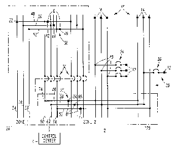
Figure 1 shows an electrical distribution system, such as switchgear 2,
including a control center 4 and acoustic sensors 6,8,10,12,14,16. In the
example
switchgear 2, circuit interrupters, such as circuit breakers 30,34,36, act as
isolators or
absorbers of acoustic signals since, for example, the braided flexible
conductor or
shunt (not shown) electrically connecting the movable contact arm (not shown)
and
the circuit breaker load side conductor (not shown) acts like an acoustic
isolator due
to the relatively high attenuation rate of the acoustic signal when it goes
through the
shunt. Hence, an acoustic signal from the load (line) side cannot pass through
the
circuit breaker to reach to the line (load) side. Since the shunt is an
acoustic
attenuator, any acoustic signal, regardless if generated from an actual
electrical
conductivity fault, will not pass through the circuit breaker, thus dividing
the
switchgear 2 into acoustically isolated zones, such as 26,28.
An example acoustic sensor system 38 provides electrical conductivity
fault detection and zone location detection in the example switchgear 2. The
example
acoustic sensors 6,8,10,12 are installed at various locations within the
example
CA 02755184 2011-10-18
10-mPCS-244(PDA)
- 7 -
switchgear 2 in such a way that each acoustic sensor covers a certain section
within
the electrical system. Each section is determined by the location of
electrical
switching devices (e.g., without limitation, circuit interrupters, such as
circuit
breakers or contactors) that act as acoustic isolators or absorbers of
acoustic signals
within the electrical distribution system. This makes it possible that no more
than one
acoustic sensor will detect the acoustic signal from the same electrical
conductivity
fault, which will provide electrical conductivity fault zone location
detection.
In Figure I, an example loose electrical connection 24 is detected by
sensor 8 in zone 28 (zone #2). However, an example loose electrical connection
22 is
not detected by sensor 8 due to blocking by circuit breaker 30. For example,
the loose
electrical connections 22,24 can occur at, for example, over-heated electrical
joints,
such as, for example, 40. Sensors 14,16 are unable to detect the loose
electrical
connection 24 due to the attenuation of the acoustic signal, or may not be
able to
confirm that the loose electrical connection 24 is in zone 28 (zone #2) due to
the
relatively low level of noise detected by those sensors 14,16 when compared
with the
relatively higher level of noise detected by sensor 8 in zone 28. Hence, the
example
switchgear 2 can also be partitioned by the distance that an acoustic signal
can travel
without significant acoustic attenuation so that, for example, a corresponding
one of
the sensors 8,14,16 can still detect the acoustic signal.
The example circuit breaker 34 is a three-pole tie circuit breaker.
The example acoustic sensor system 38 is for a three-phase electrical
distribution system, such as the example switchgear 2, although any number of
phases
can be employed. The acoustic sensor system 38 includes a plurality of sets of
acoustic sensors, such as, for example, 6,8, structured to detect an
electrical
conductivity fault of the example switchgear 2. Each of these plurality of
sets
includes three acoustic sensors, such as sensors 42,44,46. Each of the three
acoustic
sensors, such as sensors 42,44,46, is for a corresponding phase, such as
phases
48,50,52, respectively, of the example switchgear 2.
The example switchgear 2 includes a plurality of bus bars, such as
54,56,58,60,62,64, and a plurality of zones, such as the zones 26,28. For
example,
each of the three acoustic sensors 42,44,46 is coupled to a corresponding one
of the
bus bars 54,56,58, respectively, at the corresponding zone 26. Similarly, each
of the
CA 02755184 2011-10-18
10-mPCS-244(PDA)
- 8 -
three acoustic sensors 66,68,70 is coupled to a corresponding one of the bus
bars
60,62,64, respectively, at the corresponding zone 28. In this manner, the sets
of
acoustic sensors, such as, for example, 6,8, are operatively associated with
all of the
bus bars, such as, for example, 54,56,58,60,62,64, and all of the zones, such
as, for
example, 26,28, of the example three-phase switchgear 2. Each of the example
zones
26,28 is a particular location or section of the example three-phase
switchgear 2.
Referring to Figure 2, a remote station, such as example control center
100, is shown. The example control center 100 can be part of or cooperate with
a remote
monitoring system 102. Alternatively, the remote station can be a protective
relay (not
shown), which can include some or all of the functions of the control center
100. The
control station 100, for example and without limitation, may be dedicated for
the
purposes of receiving and communicating acoustic detections or may be part of
another device, such as a trip unit, a protective relay or a meter.
The example control center 100 can be operatively associated with a
plurality of different acoustic sensors 104,106,108,110 for a plurality of
different
zones 118,120,122,124, respectively (see, also, the zone (zone #1) 26 and the
zone
(zone #2) 28 of Figure 1). It will be appreciated that the acoustic sensors
104,106,108,110 can be, for example and without limitation, single-phase
acoustic
sensors for a single-phase electrical distribution system 111, or three-phase
acoustic
sensors, such as the example acoustic sensors 6,8,14,16 for the example three-
phase
switchgear 2 of Figure 1. Any number of phases can be employed.
Each of the example acoustic sensors I 04,106,108.110 is structured to
communicate with the example control center 100 using a communication system
112
between these acoustic sensors 104,106,108,110 and the control center 100 to
send an
indication of a detected electrical conductivity fault (not shown in Figure 2,
but see
the electrical conductivity faults 22,24 of Figure 1) and a corresponding zone
of the
plurality of zones (118,120,122,124, respectively) upon detection of the
electrical
conductivity fault.
Each of the example acoustic sensors 104,106,108,110 is further
structured to periodically send a communication, such as a message 114, to the
example control center 100 using the communication system 112, in order to
confirm
normal operation thereof. Each of the example acoustic sensors, such as 104,
can
CA 02755184 2011-10-18
10-mPCS-244(PDA)
- 9 -
periodically transmit the message 114 such as once every 30 minutes, although
any
suitable time period can be employed. The example communication system 112 is
selected from the group consisting of a wired communication system and a
wireless
communication system.
The various acoustic sensors 104,106,108,110, the communication
system 112, and the example control center 100 form an acoustic sensor system
116
for the electrical distribution system 111 comprising the plurality of zones
118,120,122,124, each of which has a number of electrical connections (not
shown in
Figure 2, but see the example electrical joints 40 of Figure 1). The acoustic
sensors
104,106,108,110, like the acoustic sensors 6,8,10,12,14,16 of Figure 1, are
structured
to detect an electrical conductivity fault of the electrical connections of
the various
zones 118,120,122,124. Each of the acoustic sensors 104,106,108,110 is
structured to
communicate with the example control center 100 using the communication system
112 to send an indication of a detected electrical conductivity fault and a
corresponding zone of the plurality of zones 118,120,122,124 upon detection of
the
electrical conductivity fault. For example, the example control center 100
includes a
central control unit 126 (e.g., a processor) that receives messages, such as
128, from
all of the acoustic sensors 104,106,108,110. These messages 128 include a
sensor ID
code 130 and a functional status 132, which indicates that the corresponding
acoustic
sensor, as identified by the corresponding sensor ID code 130, is either
working
properly or has detected a fault, such as an electrical conductivity fault. In
turn, the
central control unit 126 can output an alarm message to a display 134, and/or
send an
alarm 136 to the remote monitoring system 102. The display 134 and/or the
alarm
136 can then indicate either that an electrical conductivity fault was
detected in a
corresponding zone, or that the corresponding acoustic sensor is in an
operational
state.
Figure 3 shows one of the acoustic sensors 42,44,46,66,68,70 of Figure 1.
This includes a sensor housing and mounting structure 150, a piezoelectric
element 152,
an optional preload 154, an electronic circuit 156, a fault indicator 158, a
wireless
transceiver 160 and a power supply 162. The preload 154, which is not
required,
compresses the piezoelectric element 152 under pressure in its assembly. The
sensor
housing and mounting structure 150 is suitably coupled, at 164, to an
electrical power
õ . õ... ........ .
. . ......... . . . õ.õ.
10-mPCS-244(P DA)
- 10 -
conductor 166 (e.g., of the example switchgear 2 of FIG. 1 or of the example
electrical
distribution system 111 of FIG. 2). The example piezoelectric element 152 is
coupled to the
electrical power conductor 166 by a suitable insulation spacer 168 or through
the sensor housing
by a suitable insulating spacer.
Although the power supply 162 is shown as being an example parasitic power
supply or source (e.g., without limitation, employing a current transformer
(CT) (not shown) that
derives power from the energized electrical power conductor 166), it will be
appreciated that a
wide range of power supplies can be employed. The example parasitic power
supply 162
includes a power harvesting capability such as by employing a number of power
CTs to harvest
electrical power when there is current flowing through the electrical power
conductor 166. For
example and without limitation, the sensor 104 of FIG. 2 employs a battery
power supply 170
and the sensor 110 of FIG. 2 employs an external power source 172.
The wireless transceiver 160 of FIG. 3 provides a suitable wireless
communication capability (e.g., without limitation, IEEE 802.11; IEEE
802.15.4; another
suitable wireless transceiver or transmitter) to communicate the detection of
an electrical
conductivity fault to another location (e.g., without limitation, the example
control center 100 of
FIG. 2; a control console; a trip unit; a protective relay) to alert
maintenance personnel or the
fault and its zone location.
The electronic circuit 156 includes a buffer input circuit 174 that receives
the
output signal 176 from the piezoelectric element 152, an amplifier circuit
178, a bandpass filter
180, a peak detector 181 and a processor 182. A reset circuit 184 can reset
the electronic circuit
156 after a power outage caused by the parasitic power supply 162 receiving
insufficient power
from the electrical power conductor 166.
FIG. 4 is a flowchart of a routine 200 for the central communication unit 126
of
FIG. 2. First, at 202, the central communication unit 126 is powered up. Next,
at 204, it receives
a status message from "SENSOR i÷, which is one of the example acoustic sensors
104,106,108,110. Next, at 206, it confirms the status message from "SENSOR i"
and, at 208,
sends a receive confirmation message back to that particular sensor. Next, at
210, it finds the
zone location of that particular sensor based on the sensor ID code 130 in the
received status
message. Then, at 212, it checks the received status message for an electrical
conductivity fault,
such as a loose
¨ .
CA 2755184 2017-07-20
CA 02755184 2011-10-18
10-mPCS-244(PDA)
- 11 -
connection. If a fault is indicated, then at 214, a loose connection warning,
such as an
alarm, is displayed along with its zone location. Next, at 216, a
corresponding message
is sent to the remote monitoring system 102. Then, at 218, an integer, i, is
incremented
to point to the next sensor (e.g., "SENSOR i+1"). Next, at 220, if the
integer, i, is greater
than a predetermined value (e.g., N is the count of the various acoustic
sensors), then the
integer, i, is reset to one at 222, after which step 204 is repeated.
Otherwise, if the
integer, i, is not greater than the predetermined value, then execution
resumes at 204
with the integer, i, as was incremented at 218.
On the other hand, at 212, if the received status message is normal, then
at 224, a normal status is displayed for the current sensor (e.g., "SENSOR i")
along with
its zone location. Then, step 216 is executed to send a corresponding message
to the
remote monitoring system 102. As was discussed above in connection with Figure
2,
each of the acoustic sensors 104,106,108,110 periodically transmits a normal
status
message to the example control center 100 using the communication system 112,
in
order to confirm normal operation thereof.
Referring to Figures 5A-5B, a routine 250 for the processor 182 of
Figure 3 is shown. The general operation of this routine 250 is to obtain
output from
the peak detector 181 of Figure 3 and measure DELTA (step 268), the time
difference
between two adjacent signals from the peak detector 181. First, at 252, an
acoustic
signal is available at the piezoelectric element 152 and the peak acoustic
signal
therefrom is available at the peak detector 181. Next, at 254, the routine 250
inputs a
signal, f, which is the acoustic high frequency (HF) signal from the peak
detector 181.
Then, at 256, a value, fb, is determined, which is the baseline of the HT
signals using, for example, an 8-point moving average of the HF signals below
a
predetermined threshold Ll . Two Ll and L2 thresholds are employed by the
routine
250 to confirm that acoustic wavelets 251 have the intended profile
representative of
an electrical conductivity fault. Non-limiting examples of LI and L2 are 100
mV and
50 mV, respectively. Sometimes, the HF signal from the peak detector 181 has a
relatively high noise level due to various reasons such as, for example,
increased EMI
noise. In order to avoid the effect of baseline noise level variation, step
256 seeks to
take the noise level out of the measured signal by estimating the noise level
using the
example 8-point moving average on those HF signals below the predetermined
CA 02755184 2011-10-18
10-mPCS-244(PDA)
- 1, -
threshold Ll. The example 8-point moving average is the average value of the
last
example eight samples whose values are below the Ll threshold. Next, at 258,
the
corrected HF signal, fc, is determined from f- fb.
At 260, it is determined if fc is greater than Ll. If so, then it is
determined if T ¨ Tn-1 is greater than AT (e.g., a predefined value such as 5
mS) at
262. T is the time from a suitable timer (not shown) (e.g., without
limitation, an
oscillator circuit (not shown) in the processor 182 of Figure 3; a crystal
oscillator (not
shown) in the processor 182). DELTA is reset to zero at 284 (where Tn = Tn-1 =
0)
after the routine 250 reaches its predetermined time period at 276. If the
test passes at
262, then at 264, the timer value, T, is recorded as Tn. Tn = T means that
time T is
recorded as Tn when there is an acoustic signal coming out of the peak
detector 181
that is higher than the Ll threshold. Next, step 266 confirms that the
corrected HF
signal is valid if fc is greater than L2 at T = Tn + 0.1 mS. If so, then
variable DELTA
is set equal to Tn ¨ Tn- I . Then, at 270, Tn-1 is set equal to Tn.
Next, at 272, it is determined if M is less than 2 or greater than 7,
where M is the unit digit of integer [10*DELTA/8.3333]. This checks if DELTA
is a
multiple of 8.3333 mS (e.g., without limitation, DELTA/8.3333 = 2.1, then
(DELTA/8.3333) x 10 = 21, and M = 1 which is less than 2. So DELTA in this
case
can be considered as a multiple of 8.3333 mS considering the potential
measurement
error. Effectively, step 272 determines if DELTA is a multiple of one-half
line cycle
(e.g., without limitation, about 8.3 mS). M represents the digit after the
digit point,
such as, for example, M = 2 for 3.24 or M = 8 for 5.82. lithe test passes at
272 and
DELTA is a multiple of one-half line cycle, then, at 274, one is added to an X
bucket.
On the other hand, if DELTA is not a multiple of one-half line cycle, then, at
275, one
is added to a Y bucket.
After steps 274 or 275, or if the test failed at 262, then at 276, it is
determined if Tn is greater than or equal to a predetermined time (e.g.,
without
limitation, 200 mS; 2 S; 10 S; one day). If so, then at 278 and 280, the
routine 250
checks two criteria before it declares that the noise is induced by an
electrical
conductivity fault, such as a glowing contact. Step 278 checks if X + Y >= A
(e.g.,
without limitation, 10; 15; any suitable value); and step 280 checks if the
ratio of X /
(X + Y) > B (e.g., without limitation, 60%; any suitable percentage less than
100%).
CA 02755184 2011-10-18
10-mPCS-244(PDA)
- 13 -
If these two tests pass, then an alarm (e.g., the fault indicator 158 of
Figure 3) is
activated at 282. Otherwise, if one or both of these two tests fail, or after
282, the
routine 250 causes a reset after cycling of power (e.g., if power from the
power supply
162 of Figure 3 cycles; if a manual power switch (not shown) is cycled), then
values
Y, X, Tn and Tn- I are reset to zero and AT is set to 5 mS at 284, and the
next
interrupt is enabled at 286. Step 286 is also executed if any of the tests
fail at 260,
266 and/or 276. Interrupts occur periodically (e.g., without limitation, every
100 [IS).
Also, the X and Y buckets of respective steps 274 and 275 are reset to zero
after a
predetermined time (e.g., without limitation, 10,000 mS; any suitable time).
The example routine 250 is similar to those of U.S. Patent No.
7,148,696. However, it adds various features such as, for example, the L2
threshold
in order to confirm that the wavelet contour is correct for each acoustic
signal.
As will be discussed in connection with Figures 6-8, at least one of the
acoustic sensors, such as 110 of Figure 2, can be structured to clamp-on an
electrical
power conductor, such as 166 of Figure 3. For example, the three acoustic
sensors
42,44,46 can be structured to clamp-on a set of the three-phase electrical
power
conductors of phases 48,50,52, respectively, of Figure 1.
Referring to Figures 6 and 7, an acoustic sensor apparatus 300 includes
a clamp, such as the example clamp-on structure 302, for an electrical power
conductor, such as the example rectangular power bus bar 304 (shown in phantom
line drawing in Figure 6). The example acoustic sensor apparatus 300 also
includes a
housing 306 for an acoustic sensor and/or an acoustic generator, such as a low
cost
piezoelectric element 308 (shown in hidden line drawing in Figure 7) housed
within
the housing 306, and a printed circuit board (PCB) 310 (Figure 7), which can
include
the example electronic circuit 14, fault indicator 158, wireless transceiver
160,
parasitic power supply 162 and reset circuit 184 of Figure 3. The housing 306
is
clamped onto power bus bar 304 or another power conductor in an electrical
system
(not shown).
As shown in Figure 6, the exterior of the housing 306 includes an
insulation spacer 312, which is coupled to the stainless steel cylindrical
canister 318
wherein piezoelectric element 308 (shown in hidden line drawing) is disposed
(Figure
CA 02755184 2011-10-18
10-mPCS-244(PDA)
- 14 -
7). The clamp-on structure 302 is structured to clamp together the insulation
spacer
312 and the example power bus bar 304 along with the housing 306.
The housing 306 can be, for example and without limitation, a metallic
housing or an insulative housing having an internal and/or external metal
coating
structured to provide EMI shielding. The metal coating can be, for example and
without limitation, a suitable thin film metal coating.
As is best shown in Figure 7, the example clamp-on structure 302 is
disposed through opening 314 of the housing 306. The clamp-on structure 302
includes a first insulative clamp portion 316 disposed within the housing 306
and
engaging a stainless steel cylindrical canister 318 that houses the
piezoelectric
element 308 (shown in hidden line drawing) therein, a second insulative clamp
portion 320 disposed outside of the housing 306 and being structured to engage
the
power bus bar 304 (Figure 6), and a threaded coupler, such as the example
threaded
dowel 322, passing through the first clamp portion 316 and through the housing
306.
The threaded dowel 322 has a first end and an opposite second threaded end
(shown
in Figure 8) threadably coupled to the second clamp portion 320 (as shown with
the
second clamp portion 320' in Figure 8).
A rotatable member, such as the example circular, insulative fastening
knob 324, is coupled to and structured to rotate along the threaded dowel 322
in order
to move up or down to pull or push the second clamp portion 320 and clamp or
unclamp, respectively, the housing 306, the power bus bar 304 and the second
clamp
portion 320. An insulative screw cap 326 keeps the knob 324 from rotating off
the
first end of the threaded dowel 322.
Preferably, the second clamp portion 320 has an insulative cushion 328
structured to insulatively engage the power bus bar 304.
The piezoelectric element 308 is within the example 0.5" diameter
stainless steel cylindrical canister 318 and is coupled to the bottom of the
canister
318, which is opposite the side of the insulative spacer 312 (e.g., a ceramic
disk)
(Figure 6).
As shown in Figure 7, the example acoustic sensor apparatus 300
includes the fault indicator 158 of Figure 3, which can be an LED indicator
(e.g.,
without limitation, green flashing for normal operation; red flashing for
detection of
CA 02755184 2011-10-18
10-mPCS-244(PDA)
- 15 -
an electrical conductivity fault operatively associated with the power bus bar
304).
An on/off switch 330 can enable or disable the power supply 162 of Figure 3,
which
can include a battery 332 as shown in Figure 7. Also, the power supply 162 can
accept DC power from an external AC/DC or DC/DC power supply (not shown)
through DC power input 334.
As can be seen from Figures 6 and 7, the example housing 306
includes a base 336 and a cover 338. The base 336 includes posts 340, which
engage
corresponding structures (not shown) of the cover 338.
Referring to Figure 8, another clamp-on structure 342 is for a power
conductor 344 (shown in phantom line drawing in Figure 8) and another acoustic
sensor apparatus (not shown), which, except for the clamp-on structure 342,
can be
the same as or similar to the acoustic sensor apparatus 300 of Figures 6 and
7. The
second clamp portion 320' is somewhat different than the second clamp portion
320
of Figure 6. In particular, the clamp surface 346 is a concave arcuate surface
to
accommodate the circular or elliptical cross section of the power conductor
344.
Conversely, the second clamp portion 320 of Figure 6 has a flat, generally
flat or
somewhat convex surface 348 to accommodate the planar surface of the power bus
bar 304. In this example, no insulative cushion is employed since electrical
cables
usually have insulative sleeves thereon. Otherwise, the clamp-on structure
342, like
the clamp-on structure 302, can clamp together a housing, such as 306, the
power
conductor 344, and optionally an insulative spacer, such as 312.
While specific embodiments of the disclosed concept have been
described in detail, it will be appreciated by those skilled in the art that
various
modifications and alternatives to those details could be developed in light of
the
overall teachings of the disclosure. Accordingly, the particular arrangements
disclosed are meant to be illustrative only and not limiting as to the scope
of the
disclosed concept which is to be given the full breadth of the claims appended
and
any and all equivalents thereof.