Note : Les descriptions sont présentées dans la langue officielle dans laquelle elles ont été soumises.
CA 02757234 2011-09-26
WO 2010/135026
PCT/US2010/028969
METHOD AND SYSTEM FOR CONTROLLING SMOKER
DEVICE INTEGRAL TO AN OVEN
FIELD OF THE INVENTION
This invention relates to an oven with a smoker device and a method and
a system for controlling the smoker device and particularly for an oven that
is
capable of operating in a convection mode, a steaming mode and/or a smoking
mode.
BACKGROUND OF THE INVENTION
Current implementations of smoking technology in combination ovens
preclude the end user from using all of the rack capability when the smoker
device is placed in the oven chamber. The current smoking devices are too
large
in the height dimension and, thus, become an obstacle to use of the lower rail
positions, thereby reducing the cooking capacity and output. Current
implementations of control of the smoker device do not provide for an
integrated
control of the smoking device together with other food preparation assemblies
of
the oven.
Thus, there is a need for an improved oven with a smoker device
capability.
SUMMARY OF THE INVENTION
A first embodiment of an oven for cooking food products of the present
disclosure comprises an oven chamber that includes at least one side wall and
a
bottom wall. A thermal unit supplies thermal energy to the oven chamber to
cook
a food product. A smoker assembly supplies smoke to the food product. A
controller comprises a processor, a cook program and a smoke program. The
processor executes the cook program and the smoke program to operate the
1
CA 02757234 2011-09-26
WO 2010/135026
PCT/US2010/028969
thermal unit and the smoker assembly to supply thermal energy and smoke to
cook the food product.
In one aspect of the first embodiment of the oven of the present
disclosure, the cook program includes a plurality of cook procedures. The cook
program invokes the smoke program when executing at least one of the cook
procedures.
In another aspect of the first embodiment of the oven of the present
disclosure, the oven further comprises a plurality of switches and a power
source. The processor controls connections of the thermal unit and the smoker
assembly in circuit with the power source to provide thermal energy and smoke
in the oven chamber to cook the food product.
In another aspect of the first embodiment of the oven of the present
disclosure, the thermal unit is a member of the group consisting of: a
convection
assembly, a steam assembly, a radiant heat assembly, a microwave and any
combination thereof.
In another aspect of the first embodiment of the oven of the present
disclosure, the oven further comprises a control panel. The smoke program is
invoked by a user making a manual selection from the control panel.
In another aspect of the first embodiment of the oven of the present
disclosure, the smoke program is invoked by the processor based on execution
of instructions of the cook program.
In another aspect of the first embodiment of the oven of the present
disclosure, the oven chamber comprises a plurality of pan racks that include a
plurality of shelf holders. The smoker assembly comprises a heater element and
a pan that contains a smoke media. The pan and the heater element are shaped
2
CA 02757234 2011-09-26
WO 2010/135026
PCT/US2010/028969
for disposition in the oven chamber below a lowermost one of the shelf holders
and above the bottom wall.
In another aspect of the first embodiment of the oven of the present
disclosure, the heater element comprises an upper level, which extends through
the side wall and a lower level that supports the pan below the lowermost
shelf
holder and above the bottom wall.
In another aspect of the first embodiment of the oven of the present
disclosure, the heater element comprises first and second spaced apart legs in
the upper level and in the lower level and a portion in the lower level that
connects to the first and second legs. Each of the first and second legs
includes
an incline between the upper and lower levels.
In another aspect of the first embodiment of the oven of the present
disclosure, the pan comprises a slot and wherein the lower level of the heater
element is disposed in the slot.
In another aspect of the first embodiment of the oven of the present
disclosure, the pan further comprises a plurality of apertures that allow
smoke to
pass into the oven chamber.
In another aspect of the first embodiment of the oven of the present
disclosure, the pan further comprises a lid that is installed and removed in a
sliding motion.
In another aspect of the first embodiment of the oven of the present
disclosure, the pan further comprises a handle that is removably attached to
the
lid.
3
CA 02757234 2011-09-26
WO 2010/135026
PCT/US2010/028969
A method of the present disclosure cooks food in an oven that includes an
oven chamber that includes at least one side wall and a bottom wall. The
method comprises:
supplying thermal energy with a thermal unit to the oven chamber to cook
a food product;
supplying smoke with a smoker assembly to the food product; and
controlling a processor with a cook program and a smoke program to
operate the thermal unit and the smoker assembly to supply thermal energy and
smoke to cook the food product.
In one embodiment of the method of the present disclosure, the cook
program includes a plurality of cook procedures, and wherein the cook program
invokes the smoke program when executing at least one of the cook procedures.
In another embodiment of the method of the present disclosure, the
processor controls connections of the thermal unit and the smoker assembly in
circuit with a power source to provide thermal energy and smoke in the oven
chamber to cook the food product.
In another embodiment of the method of the present disclosure, the
thermal unit is a member of the group consisting of: a convection assembly, a
steam assembly, a radiant heat assembly, a microwave and any combination
thereof.
In another embodiment of the method of the present disclosure, the
smoke program is invoked by a user making a manual selection from a control
panel of the oven.
In another embodiment of the method of the present disclosure, the
smoke program is invoked by the processor based on execution of instructions
of
the cook program.
4
CA 02757234 2011-09-26
WO 2010/135026
PCT/US2010/028969
In another embodiment of the method of the present disclosure, the oven
chamber comprises a plurality of pan racks that include a plurality of shelf
holders. The smoker assembly comprises a heater element and a pan that
contains a smoke media. The pan and the heater element are shaped for
disposition in the oven chamber below a lowermost one of the shelf holders and
above the bottom wall.
In another embodiment of the method of the present disclosure, the heater
element comprises an upper level, which extends through the side wall and a
lower level that supports the pan below the lowermost rack and above the
bottom
wall.
In another embodiment of the method of the present disclosure, the pan
comprises a slot and wherein the lower level of the heater element is disposed
in
the slot.
In a second embodiment of the oven of the present disclosure, the oven
for cooking food products comprises an oven chamber comprising at least one
side wall, a bottom wall, and a plurality of pan racks disposed on the side
wall
that include a plurality of shelf holders. A thermal unit supplies thermal
energy to
the oven chamber to cook a food product. A smoker assembly supplies smoke
to the food product. The smoker assembly comprises a heater element and a
pan that contains a smoke media. The pan and the heater element are shaped
for disposition in the oven chamber below a lowermost one of the shelf holders
and above the bottom wall.
In one aspect of the second embodiment of the oven of the present
disclosure, the heater element comprises an upper level, which extends through
the side wall and a lower level that supports the pan below the lowermost
shelf
holder and above the bottom wall.
CA 02757234 2015-07-07
In another aspect of the second embodiment of the oven of the present
disclosure, the heater element comprises first and second spaced apart legs
in the upper level and in the lower level and a portion in the lower level
that
connects to the first and second legs. Each of the first and second legs
includes an incline between the upper and lower levels.
In another aspect of the second embodiment of the oven of the present
disclosure, the pan comprises a slot and the lower level of the heater element
is disposed in the slot.
In another aspect of the second embodiment of the oven of the present
disclosure, the pan further comprises a plurality of apertures that allow
smoke
to pass into the oven chamber.
In another aspect of the second embodiment of the oven of the present
disclosure, the pan further comprises a lid that is installed and removed in a
sliding motion.
In another aspect of the second embodiment of the oven of the present
disclosure, the pan further comprises a handle that is removably attached to
the lid.
In another aspect, there is provided an oven for cooking food products
comprising:
an oven chamber comprising at least one side wall and a bottom wall;
a thermal unit that supplies thermal energy to said oven chamber to
cook a food product;
a smoker assembly that supplies smoke to said food product; and
a controller that comprises a processor, a cook program and a smoke
program, wherein said processor executes said cook program and said
smoke program to operate said thermal unit and said smoker assembly to
supply said thermal energy and said smoke to cook said food product,
wherein said oven chamber comprises a plurality shelf holders, wherein said
smoker assembly comprises a heater element and a pan that contains a
6
CA 02757234 2015-07-07
smoke media, wherein said pan and said heater element are shaped for
disposition in said oven chamber below a lowermost one of said shelf holders
and above said bottom wall, and wherein said heater element comprises an
upper level which extends through said side wall and a lower level that
supports said pan below said lowermost shelf holder and above said bottom
wall.
In another aspect, there is provided a method for cooking food in an
oven that includes an oven chamber that includes at least one side wall and a
bottom wall, said method comprising:
supplying thermal energy with a thermal unit to said oven chamber to
cook a food product;
supplying smoke with a smoker assembly to said food product; and
controlling a processor with a cook program and a smoke program to
operate said thermal unit and said smoker assembly to supply said thermal
energy and said smoke to cook said food product, wherein said oven chamber
comprises a plurality of shelf holders, wherein said smoker assembly
comprises a heater element and a pan that contains a smoke media, wherein
said pan and said heater element are shaped for disposition in said oven
chamber below a lowermost one of said shelf holders and above said bottom
wall, and wherein said heater element comprises an upper level which
extends through said side wall and a lower level that supports said pan below
said lowermost shelf holder and above said bottom wall.
In another aspect, there is provided an oven for cooking food products
comprising:
an oven chamber comprising at least one side wall, a bottom wall, and
a plurality of pan racks disposed on said side wall, wherein said pan racks
include a plurality of shelf holders;
a thermal unit that supplies thermal energy to said oven chamber to
cook a food product; and
a smoker assembly that supplies smoke to said food product;
6a
CA 02757234 2015-07-07
wherein said smoker assembly comprises a heater element and a pan
that contains a smoke media, and wherein said pan and said heater element
are shaped for disposition in said oven chamber below a lowermost one of
said shelf holders and above said bottom wall, and wherein said heater
element comprises an upper level which extends through said side wall and a
lower level that supports said pan below said lowermost shelf holders and
above said bottom wall.
BRIEF DESCRIPTION OF THE DRAWINGS
Other and further objects, advantages and features of the present
invention will be understood by reference to the following specification in
conjunction with the accompanying drawings, in which like reference
characters denote like elements of structure and:
Fig. 1 is a perspective view of the oven according to the present
invention;
6b
CA 02757234 2011-09-26
WO 2010/135026
PCT/US2010/028969
Fig. 2 is a partial perspective view of an internal structure of the oven of
Fig. 1;
Fig. 3 is a partial perspective view of Fig. 2 with smoker assembly offset
from installed position;
Fig. 4 is a perspective view of the smoker assembly disassembled of the
oven of Fig. 1;
Fig. 5 is a perspective view of the smoker assembly of the oven of Fig. 1;
Fig. 6 is a view taken along line 6 of Fig. 2;
Fig. 7 is a block diagram of the control section of Fig. 2; and
Fig. 8 is a flow diagram of the smoke program of the control assembly of
Fig. 7.
DESCRIPTION OF THE PREFERRED EMBODIMENT
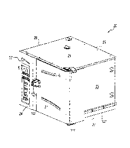
Referring to Figs. 1-3, an oven system of the present invention comprises
an oven 20 that includes an external structure that comprises an external top
21,
an external side 23, and external side 25, an external bottom 27, an external
back 29, a door 31 and a control panel 33. Oven 20 further includes an
internal
structure that is supported within the external structure and that comprises
an
oven chamber 22 defined by an internal back wall 28, an internal bottom wall
30,
an internal top wall (not shown), an internal side wall 24 and an internal
side wall
(not shown) disposed opposite side wall 24 and offset internally of external
side
wall 23. Door 31 covers a front of oven chamber 22. A control section 32 is
disposed behind control panel 33 outside of oven chamber 22 and between
internal side wall 24 and external side wall 25. Oven 20 also includes a
smoker
assembly 34 and a thermal energy unit that comprises a steamer assembly 36
7
= CA 02757234 2011-09-26
WO 2010/135026
PCT/US2010/028969
and a heater assembly 38. In alternate embodiments, the thermal unit may
comprise steamer assembly 36, heater assembly 38, a microwave assembly (not
shown) or a combination thereof.
Heater assembly 38 may be comprised of any suitable heater, such as a
convection heater, a radiant heater and the like, that provides thermal energy
to
cook a food product. For the purpose of the present disclosure, heater
assembly
38 is described herein as a convection heater, which comprises a fan (not
shown) and a heater (not shown) that are disposed in a fan box (not shown) and
that are in fluid communication with oven chamber 22 to circulate heated
convection air between the fan box and oven chamber 22. The heater may be
any suitable oven heater, such as gas, electric and the like. The fan is
located to
inject air into oven chamber 22 via one or more ingress openings and to suck
air
in from one or more egress openings of oven chamber 22. The ingress openings
and egress openings may be located in any of the side walls 24 and 26, bottom
wall 30, back wall 28 and the top wall (not shown). For example, the ingress
openings may be located in the top wall (not shown) and the egress openings
may be located in back wall 28.
Steamer assembly 36 is preferably located within oven 20, but outside
oven chamber 22. For example, steamer assembly 36 is disposed to convert
water into steam in the circulating hot air flow by flashing water on a heated
surface, such as the convection air heater or a surface, which it heats, such
as
blades of the fan. Alternately, steamer assembly 36 can be independent of oven
20 with steam generated by steamer assembly 36 being conveyed to oven 20 via
a tube, pipe or other conduit.
Referring to Figs. 2 and 3, a pair of spaced apart pan racks 43 and 45 is
disposed in oven chamber 22. Pan racks 43 and 45 each comprise a plurality of
shelf holders 40 to hold wire shelves 42, of which one wire shelf is shown in
Fig.
8
CA 02757234 2011-09-26
WO 2010/135026
PCT/US2010/028969
6. In alternate embodiments, steaming or baking pans can be used instead of
wire shelves.
Referring also to Figs. 2-6, smoker assembly 34 comprises a heater
element 50 and a pan 70. Heater element 50 comprises two side rails 52 and 54
that are threaded through openings 56 in back wall 28 and that are connected
at
their distal ends to a connector rail 64. Heater element 50 is connected via
side
rails 52 and 54 in electrical circuit with a switch and a power source as
described
hereinafter. Heater element 50 is located just above bottom wall 30 and far
enough below the lowest rack 40 to allow enough space for pan 70 without any
interference with the lowermost shelf 42 as shown in Fig. 6.
In a preferred embodiment, side rail 52 has a high level member 55 that is
connected to a low level member 60 via an angled member 57 and side rail 54
has a high level member 58 that is connected to a low level member 61 via an
angled member 59. The distal ends of side rail lower members 60 and 61 are
interconnected via a bridge member 64 that contains a U-shaped bend 66
between and at the same level as lower members 60 and 61. As shown in Figs.
3 and 6, high level members 55 and 58 of heater element 50 enter oven chamber
22 via openings 54 in back wall 28 at a first high level 44 above bottom wall
30.
Heater element 50 then angles or inclines downwardly via angled members 57
and 59 to low level members 60 and 61, which are at a second low level 46
above and closer to bottom wall 30.
Referring to Figs. 4 and 5, pan 70 includes a media container 72, a
removable lid 74 and a handle 76. Media container 72 comprises a box having a
front wall 78, a back wall 80, a bottom wall 82 and side walls 84 and 86. A
plurality of vent holes 88 are disposed in front wall 78, bottom wall 82 and
side
walls 84 and 86 for smoke to escape into oven chamber 22.
9
CA 02757234 2011-09-26
WO 2010/135026
PCT/IJS2010/028969
A low profile slot 90 is disposed in back wall 80 to allow entry of heater
element 50 into media container 72. Side walls 84 and 86 include at their
upper
edges flanges 92 for mating engagement with removable lid 74. Smoking media
94 can be inserted into media container and heated by heater element 50 to
produce smoke that is vented via vent holes 88 into oven chamber 22. Smoking
media 94 can be any suitable smoking material, such as, wood chips (flavored
or
natural), processed biscuits and the like.
Removable lid 74 includes a flat portion 96 that matches the shape of
media container 72 (rectangular, square, circular, and the like). Flat portion
96
includes flanges 98 on its side edges that matingly engage flanges 92 of media
container 72 for a sliding motion during installation on or removal from media
container 72. Flat portion 96 also includes a stop member 100 that extends
downwardly from its back edge to engage back wall 80 of media pan 72 to stop
the sliding motion of removable lid 74 during installation. Flat portion 96
further
includes a slot 102 that receives handle 76. Flat portion 96 is dimensioned so
that when covering media container 72 a front part of flat portion 96
including slot
102 extends beyond front wall 78.
Handle 76 includes a grip 104 that is attached to a member 106 that has
at its distal end and a vertical tab 108 that mates with slot 102 of removable
lid
72.
Pan 70 has a low profile so as to fit between the lowermost rack 40 and
bottom wall 40 of oven chamber 22. The end user can utilize all of the racks,
thereby enhancing the cooking capacity. Pan 70 also is dimensioned with an
overall area to accommodate an adequate amount of smoking media 94. Pan 70
is constructed with any suitable material and preferably is stainless steel.
Pan 70
can be left in oven chamber 22 during a cleaning cycle of oven 20. Pan 70 can
easily be installed and removed from oven chamber 22 for changing cooking
conditions when smoking is desired or not desired. Heater element 50 is robust
CA 02757234 2011-09-26
WO 2010/135026
PCT/US2010/028969
enough to withstand typical end user incidental contact (e.g., wire shelves,
baking sheets and the like). Heater element 50 is designed to operate between
25 to 30 watts per square inch of surface area to provide an optimum heat of
430 F for kindling wood (producing smoke) without igniting the wood
(producing
flame).
Referring to Figs. 2 and 7, control section 32 houses a controller 122 and
a power source 124. Control panel 33 includes buttons or other interface that
allow an end user to select a steam mode, a hot air mode, a combi mode and a
smoke mode. A combi mode includes convection heat and steam. Control panel
33 also includes a set time selector that allows the end user to select a set
time,
which, for example, is the amount of time smoker assembly 34 operates.
Controller 122 responds to end user selections on control panel 33 to
control smoker assembly 34, steamer assembly 36 and heater assembly 38 to
perform a cook procedure for a food product. Controller 122 includes a
processor 126, a memory 128, a switch control 130 and switches 132. Memory
128 includes a smoke program 134, a cook program 136 and a timer 138.
Although shown separately, smoke program 134, cook program 136 and timer
138 can be combined in one or two programs. For example, smoke program 134
and cook program 136 can be combined in one program. Alternately, cook
program 136 may comprise a plurality of cook procedures. Smoke program 134
can be invoked by any of the cook procedures or by processor 126 when
executing instructions of the cook procedures.
When the end user selects one of the cooking modes from control panel
33, processor 126 invokes one or more of the cook program(s) needed for the
selected mode. Processor 126 then executes or runs the invoked program(s) by
issuing commands to switch control 130 to control switches 132 to provide
electrical energy from power source 124 to the selected one or more of smoker
assembly 34, steamer assembly 36 and heater assembly 38.
11
CA 02757234 2011-09-26
WO 2010/135026
PCT/US2010/028969
Referring to Fig. 8, a flow diagram includes a combination of smoke
program 134 and cook program 136. As noted at box 140, oven 120, for the
purpose of the present description, is in an idle mode in which the convection
fan
and heater and the steamer are switched to an off idle position. For example,
in
the idle mode, processor 126 commands switch control 130 to turn the
convection fan off, switch control 130 and control switches 132 to provide
reduced power to the convection heater to maintain an idle temperature in oven
chamber 22 and to turn steam assembly 34 off. A display (not shown) of control
panel 120 shows cooking set time and temperature. The procedures may be
either manual or automatic. If automatic, the display indicates the set time
and
the set temperature. If manual, the display indicates a set time of 00.00 and
controller 122 awaits an end user entry of a set time.
Smoke program 134 can be incorporated into any step of an automatic
cook program. Alternately, smoke program 134 can be manually performed prior
to or at the end of execution of an automatic cook program. Box 142 represents
a capability of smoke program 134 to be run manually.
If the end user selects smoke and manual from control panel 120, step
144 prompts the end user to enter a set time. At step 146, processor 126
responds to this selection and entry of set time to command switch control 130
to
control switches 132 to turn on heater element 50 of smoker assembly 34 and
initializes timer 138 to begin a count down. Also, processor 126 can keep the
convection fan and the convection heater element off for the duration of the
count
down. At step 148, processor 126 responds to the count down reaching the end
of count down (e.g., 00:00), by commanding switch control 130 to control
switches 132 to turn heater element 50 of smoker assembly 34 off and to return
oven 20 to the idle state. At step 150 the smoking operation is complete and
smoke program 134 is exited.
12
CA 02757234 2015-07-07
Should the end user select from the control panel 120 an automatic
cook procedure or recipe, which includes the smoke operation as a step,
processor 126 responds to the pressing of a start button (not shown) at step
152. At step 154 processor executes the first step of the programmed recipe
with the selected mode, steam, combi or hot air. At step 156 cook program
136 begins the smoke option. At step 158, processor 126 commands control
switches 132 to turn on heater element 50 of smoker assembly 34 and causes
timer 138 to begin a count down of a predetermined time. Also, processor
126 can keep the convection fan and the convection heater element off for the
duration of the count down. At step 160 processor 126 responds to the timer
reaching the end of the count down, by commanding switch control 130 to
control switches 132 to turn off heater element 50 of smoker assembly 34. At
step 162 it is determined if the last step of the recipe has been completed.
If
so, step 165 returns oven 20 to the idle state. If at step 162 it is
determined
that the recipe has more steps, the processor runs the remaining recipe steps.
When the remaining steps of the recipe have been completed, at step 165 the
processor returns oven 20 to the idle state. Box 166 represent the end of
cook program 136 and processor 126 exits program 136.
The present invention having been thus described with particular
reference to the preferred forms thereof, it will be obvious that various
changes and modifications may be made therein without departing from the
scope of the present invention as defined in the appended claims.
13