Note : Les descriptions sont présentées dans la langue officielle dans laquelle elles ont été soumises.
CA 02758138 2011-10-07
WO 2010/116232 PCT/IB2010/000754
TITLE OF INVENTION
[0001] ENHANCED LUBRICATION SKEWED ROLLER CLUTCH ASSEMBLY
AND ACTUATOR INCLUDING IT
CROSS-REFERENCE TO RELATED APPLICATIONS
[0002] This application is a continuation-in-part (CIP) of co-pending
application
U.S. Serial No. 11/458,001, filed July 17, 2006, in the names of Don R.
Cavalier
and Aaron M. Klap for a "Flap Actuator," which is incorporated by reference
herein
in its entirety.
FIELD OF THE INVENTION
[0003] This invention relates generally to aircraft flight control surface
actuation,
and in particular, to a roller clutch assembly for controlling operation and
movement
of a flight control surface actuator and an actuator including same.
BACKGROUND OF THE DISCLOSURE
[0004] The maneuverability of an aircraft depends heavily on the movement of
hinged sections or flaps located at the trailing edges of the wings. By
selectively
extending and retracting the flaps, the aerodynamic flow conditions of the
wings may
be influenced so as to increase or decrease the lift generated by the wings.
For
example, during the take-off and landing phases of a flight, the position of
the flaps
of the aircraft are adjusted to optimize the lift and drag characteristics of
the wing. It
can be appreciated the reliable operation of the flaps is of critical
importance to an
aircraft.
-1-
CA 02758138 2011-10-07
WO 2010/116232 PCT/IB2010/000754
BRIEF SUMMARY OF THE INVENTION
[0005] A roller clutch assembly for use in an actuator is provided that
includes a
roller cage and at least one roller. A lubricating medium at least partially
surrounds
the roller cage and the roller. The roller cage includes at least one wiper
configured to move the lubricating medium toward its functional location
adjacent
the rollers. An aircraft actuator for controlling movement of an aircraft
flight control
surface is also provided that includes a ball nut and a ball screw operatively
connected to the flight control surface. A one-way roller clutch is
operatively
connected to the ball nut and substantially prevents rotation of the ball nut
in a first
direction in response to a compressive force on the ball screw. A roller
clutch
assembly according to the present invention is positioned between the ball nut
and
the one-way roller clutch.
BRIEF DESCRIPTION OF THE DRAWINGS
[0006] The drawings furnished herewith illustrate a preferred construction of
the
present invention in which the above advantages and features are clearly
disclosed
as well as others which will be readily understood from the following
description of
the illustrated embodiment.
[0007] In the drawings:
[0008] Fig. 1 is an isometric view of a flap actuator in accordance with the
present invention mounted on a wing of a conventional aircraft;
[0009] Fig. 2 is an isometric view of the flap actuator of the present
invention;
[0010] Fig. 3 is a cross-sectional view of the flap actuator of the present
invention
taken along line 3-3 of Fig. 2;
[0011] Fig. 4 is a cross-sectional view of a flap actuator of the present
invention
taken along line 4-4 of Fig. 3; and
[0012] Fig. 5 is a cross-sectional view of a flap actuator of the present
invention
-2-
CA 02758138 2011-10-07
WO 2010/116232 PCT/IB2010/000754
taken along line 5-5 of Fig. 2.
[0013] Fig. 6 is an enlarged cross-sectional view of a flap actuator,
including a
roller clutch assembly according to an embodiment of the present invention.
[0014] Fig. 7 is a side view of a roller cage according to an embodiment of
the
present invention.
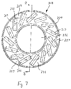
[0015] Fig. 8 is a cross-sectional view of the roller cage of Fig. 7.
DETAILED DESCRIPTION OF THE PREFERRED EMBODIMENT
[0016] Referring to Figs. 1-2, a flap actuator in accordance with the present
invention is generally designated by the reference numeral 10. As is
conventional,
an aircraft includes wing 12 projecting laterally from the fuselage (not
shown). Wing
12 includes a forward end and a trailing end 14. Trailing end 14 of flap 18
includes
flap receiving recess 16 formed therein for receiving flap 18. Flap receiving
recess
16 in trailing end 14 of wing 12 is defined by first and second generally
parallel sides
20 and 22, respectively. Trailing ends 20a and 22a of corresponding sides 20
and
22, respectively, intersect trailing edge 14 of wing 12. Leading ends 20b and
22b of
corresponding first and second sides 20 and 22, respectively, intersect frame
member 24 of wing 12. Frame member 24 projects laterally from and is
operatively
connected to the fuselage of the aircraft.
[0017] Flap 18 includes first side 26 pivotably connected to side 20 of wing
12
and second side 28 pivotably connected to side 22 of wing 12. As is
conventional,
flap 18 is pivotable about a longitudinal axis adjacent to and parallel to the
leading
edge 30 of flap 18 and movable between an extended and a retraction position.
Flap actuator 10 interconnects flap 18 adjacent the leading edge 30 thereof to
frame
member 24 of wing 12 in order to control movement of flap 18.
[0018] Flap actuator 10 includes a brushless DC motor 32 rigidly connected to
housing 124 in any suitable manner such as bolts or the like. Motor 32 is
electrically
-3-
CA 02758138 2011-10-07
WO 2010/116232 PCT/IB2010/000754
coupled to a controller for receiving electrical power and converting the same
into
mechanical power. Motor 32 includes a drive shaft (not shown) rotatable in
first and
second directions in accordance with instructions received from the
controller. It is
intended that the mechanical power generated by motor 32 be transmitted to
ball
screw 98 through spur gear assembly 36, for reasons hereinafter described. It
is
noted that in the drawings, flap actuator 10 is orientated such that motor 32
projects
away from the fuselage of the aircraft. It can be appreciated that flap
actuator 10
may be orientated such that motor 32 projects toward the fuselage of the
aircraft
without deviating from the scope of the present invention.
[0019] Referring to Fig. 4, spur gear assembly 36 includes clutch gear 40
mounted on clutch shaft 44 extending along a longitudinal axis. Clutch shaft
44
includes a first end 44a rotatably supported by bearing cage 46 and a second
opposite end 44b supporting by bearing cage 48. Clutch shaft 44 further
includes
clutch plate 50 projecting radially from a location adjacent first end 44a. A
first set of
roller bearings 52 are captured between clutch plate 50 and a first side of
clutch
gear 40. A second set of roller bearings 54 are captured between a second side
of
clutch gear 40 and a first side of thrust plate 56 which extends about clutch
shaft 44.
Belleville spring 58 is captured between a second side of thrust plate 56 and
adjustment nut 60 threaded onto clutch shaft 44. Pinion 62 projects radially
from
clutch shaft 44 adjacent second end 44b thereof.
[0020] When assembled, it is intended for belleville spring 58 to compress
thrust
plate 56, first and second roller bearings 52 and 54, respectively, and clutch
gear 40
against clutch plate 50 so as to translate rotation (or more precisely, power)
of clutch
gear 40 to clutch shaft 44 under normal operating positions. In operation, the
outer
surface of drive shaft of motor 32 meshes with and drives clutch gear 40 in a
user
desired direction. If the torque generated on clutch gear 40 is below a
predetermined threshold, rotation of clutch gear 40 is translated to clutch
shaft 44.
In the event that the torque on clutch gear 40 extends a predetermined
threshold
-4-
CA 02758138 2011-10-07
WO 2010/116232 PCT/IB2010/000754
(e.g., if a downstream component of flap actuator 10 is locked in position),
clutch
gear 40 slips on clutch shaft 44 such that rotation of clutch gear 40 is not
translated
to clutch shaft 44. The torque threshold may be adjusted by varying the spring
force
generated by belleville spring 58 on thrust plate 56 via adjustment nut 60.
[0021] Pinnion 62 meshes with and drives spur gear 64. Inner diameter of spur
gear 64 is keyed to the outer diameter of bevel shaft 66. Bevel shaft 66 is
rotatably
supported by first and second bearing cages 70 and 72, respectively. Washer 74
and nut 76 combination are mounted on first end 78 of bevel shaft 66 to
maintain
first and second bearing cages 70 and 72, respectively, and spur gear 64
thereon.
Second end 80 of bevel shaft 76 includes enlarged bevel pinion 82 projecting
therefrom. Bevel pinion 82 meshes with teeth 84 of bevel gear 86 in order to
translate rotation of bevel pinion 82 to bevel gear 86.
[0022] Referring to Fig. 3, bevel gear 86 has a splined inner surface 88 that
meshes with outer surface 90 of ball nut 92. Threads 94 along the inner
diameter of
ball nut 90 mesh with threads 96 along the outer surface of ball screw 98 for
reasons hereinafter described. Ball screw 98 further includes central
passageway
98a adapted for receiving inner rod 99 therethrough. It is intended for inner
rod 99
to maintain the integrity of ball screw 98 in the event of a fracture of ball
screw 98.
Inner rod 99, and hence ball screw 98, extends along a longitudinal axis and
includes enlarged head 100 on a first end 102 thereof. Reinforced aperture 104
extends through head 200 of ball screw 98. As best seen in Fig. 1, head 100 of
ball
screw 98 is interconnected to wing 18 adjacent leading edge 30 thereof through
aperture 104. Second end 105 of inner rod 99 includes a seal 107 and nut 109
combination secured thereon for maintaining ball screw 98 on inner rod 99 and
preventing unwanted material from entering the central passageway 98a.
[0023] In order to prevent axial movement (from right to left in Fig. 3) of
ball
screw 98 under pressure of a compressive load on the surfaces of flap 18, and
hence movement of flap 18 during operation of an aircraft, no-back assembly
106 is
-5-
CA 02758138 2011-10-07
WO 2010/116232 PCT/IB2010/000754
provided. No-back assembly 106 includes trailing thrust plate 108 and is
positioned
against shoulder 110 projecting radially from ball nut 92. Skewed roller 112
is
positioned between trailing thrust plate 108 and leading thrust plate 114.
Leading
thrust plate 114 is generally tubular and includes an inner diameter about the
outer
periphery of ball nut 92 and plate element 116 projecting radially from a
first end
thereof. Thrust washer 118 and thrust bearing 120 are positioned between
support
surface 122 of housing 124 and plate element 116 of thrust plate 114. One-way
roller clutch 126 is disposed between outer surface 128 of thrust plate 114
and inner
surface 130 of housing 124.
[0024] Roller clutch 126 only allows rotation of thrust plate 114 in a single
direction, e.g., clockwise. As such, with ball screw under a compressive load,
thrust
plate 108 engages skewed roller 112 and urges skewed roller against thrust
bearing
120. Due to the friction developed between ball nut flange 110, thrust plate
108,
skewed roller 112 and thrust plate 114, clutch roller 126 prevents further
rotation of
ball screw 98 in the clockwise direction.
[0025] Housing 124 is interconnected to frame element 124 of wing 12 by
primary and secondary gimbals 134 and 136, respectively, Fig. 5. As best seen
in
Fig. 3, it is contemplated for housing 124 to include main portion 125 and
secondary
portion 127 attached thereto by a plurality of through bolts 129, Fig. 2.
Housing 124
includes spaced upper primary gimbal mounting tabs 138 and 140, respectively,
projecting from leading end 125a of main portion 125 of housing 124. Upper
primary gimbal mounting tabs 138 and 140, respectively, are generally U-shaped
and include corresponding apertures 142 and 144, respectively, therethrough.
Spaced lower primary gimbal mounting tabs 146 and 148, respectively, project
from
leading end 125a of main portion 125 of housing 124. Lower primary gimbal
mounting tabs 146 and 184 are generally U-shaped and include corresponding
apertures 150 and 152, respectively therethrough. Apertures 142 and 144
through
upper primary gimbal mounting tabs 138 and 140, respectively, are axially
aligned
-6-
CA 02758138 2011-10-07
WO 2010/116232 PCT/IB2010/000754
with apertures 150 and 152 though corresponding lower primary gimbal mounting
tabs 146 and 148, respectively, for reasons hereinafter described.
[0026] Housing 124 further includes spaced upper secondary gimbal mounting
tabs 154 and 156, respectively, extending from leading end 127a of secondary
portion 127 of housing 124. Upper secondary gimbal mounting tabs 154 and 156
are generally U-shaped and include corresponding apertures 158 and 160,
respectively, therethrough. Spaced lower secondary gimbal mounting tabs 162
and
164, respectively, project from leading end 127a of secondary portion 127 of
housing 124. Lower secondary gimbal mounting tabs 162 and 164 are generally U-
shaped and include corresponding apertures 166 and 168, respectively,
therethrough. Apertures 158 and 160 through upper secondary gimbal mounting
tabs 154 and 156, respectively, and apertures 166 and 168 through lower
secondary
gimbal mounting tabs 162 and 164, respectively, are axially aligned with each
other
and with apertures 142, 144, 150 and 152.
[0027] Referring back to Fig. 5, primary gimbal 134 has a generally square
configuration and is defined by upper and lower walls 170 and 172,
respectively
having apertures176 and 178, respectively, therethrough. Primary gimbal 134 is
further defined by first and second sidewalls 177 and 179, respectively,
having
corresponding apertures (not shown) therethrough, for reasons hereinafter
described.
[0028] Secondary gimbal 136 also has a square-like configuration and includes
upper and lower walls 180 and 182, respectively. Upper and lower walls 180 and
182, respectively, of secondary gimbal 136 include corresponding apertures 184
and 186, respectively therethrough. In addition, secondary gimbal 136 is
defined by
first and second sidewalls 188 and 190, respectively, having corresponding
apertures (not shown) therethrough.
[0029] In order to mount housing 124 to wing 12, upper gimbal 134 is
positioned
such that upper wall 170 of primary gimbal 134 is received between upper
primary
-7-
CA 02758138 2011-10-07
WO 2010/116232 PCT/IB2010/000754
gimbal mounting tabs 138, and 140 and such that lower wall 172 of primary
gimbal
134 is received between lower primary gimbal mounting tabs 146 and 148. In
addition, aperture 176 through upper wall 170 of primary gimbal 134 is axially
aligned with apertures 142 and 144 through upper primary gimbal mounting tabs
138 and 140, respectively, and such that aperture 178 through lower wall 172
of
primary gimbal 134 is axially aligned with apertures 150 and 152 through
primary
gimbal mounting tabs 146 and 148, respectively.
[0030] Secondary gimbal 136 is positioned such that upper wall 180 of
secondary gimbal 136 is received between upper secondary gimbal mounting tabs
154 and 156 and such that lower wall 182 of secondary gimbal 136 is received
between lower secondary gimbal mounting tabs 146 and 148. Aperture 184 through
upper wall 180 of secondary gimbal 136 is axially aligned with apertures 158
and
160 through upper secondary gimbal mounting tabs 154 and 156, respectively,
and
aperture 186 through lower wall 182 of secondary gimbal 136 is axially aligned
with
apertures 166 and 168 through lower secondary gimbal mounting tabs 162 and
164,
respectively.
[0031] Once primary and secondary gimbals 134 and 136, respectively, are
positioned as heretofore described, upper pin 190 is inserted through aperture
142
in upper primary gimbal mounting tab 138; aperture 176 through upper wall 170
of
primary gimbal 134; aperture 144 through upper primary gimbal mounting tab
140;
aperture 158 through upper secondary gimbal mounting tab 154; aperture 184
through upper wall 180 of secondary gimbal 136; and aperture 160 through upper
secondary gimbal mounting tab 156. In addition, pin 192 is inserted through
aperture 150 in lower primary gimbal mounting tab 146; aperture 178 through
lower
wall 172 of primary gimbal 134; aperture 152 through lower primary gimbal
mounting
tab 148; aperture 166 through lower secondary gimbal mounting tab 162;
aperture
186 through lower wall 182 of secondary gimbal 136; and through aperture 168
through lower secondary gimbal mounting tab 164. Thereafter, primary gimbal
134
-8-
CA 02758138 2011-10-07
WO 2010/116232 PCT/IB2010/000754
is positioned within mounting bracket 194 projecting in a trailing direction
from frame
element 24 of wing 12. Spherical bearings incorporating a mounting pin are
seated
in the aperture in sidewall 177 of primary gimbal 134 and in the aperture in
sidewall
188 of secondary gimbal 136 to rigidly connect flap actuator 10 to mounting
bracket
194. Similarily, spherical bearings incorporating a mounting pin are seated in
the
aperture in sidewall 179 of primary gimbal 134 and in the aperture in sidewall
190 of
secondary gimbal 136 to rigidly connect flap actuator 10 to bracket 194.
[0032] In operation, a controller, responsive to pilot control, actuates motor
32 so
as to rotate the drive shaft in a user desired direction. Spur gear assembly
36
translates rotation of the drive shaft to bevel gear 86 which, in turn,
rotates ball nut
92 about the longitudinal axis of inner rod 99. Rotation of ball nut 92 is
translated to
ball screw 98 which, in turn, moves linearly along the longitudinal axis of
inner rod
99. By way of example, rotation of ball nut 92 in a clockwise direction causes
ball
screw 98 to move in a first linear direction and rotation of ball nut 92 in a
counterclockwise direction causes ball screw 98 to move in a second opposite
linear
direction. In such manner, ball screw 98 may be moved from an extended
position
to a retracted position, thereby allowing the position of flap 10 to be
adjusted.
[0033] During operation of the aircraft, a compressive force (from right to
left in
Fig. 3) may be provided on first end 102 of inner rod 99 and on ball screw 98
by flap
18. This compressive force is translated through no-back assembly 106, as
heretofore described, to housing 124. Thereafter, the compressive load is
translated through pins 190 and 192 to primary and second gimbals 134 and 136,
respectively, and though the spherical bearings of the primary and second
gimbals
134 and 136, respectively, to wing 18. It can be appreciated that the
arrangement
of flap actuator 10 provides redundant load sharing of any compressive force
generated by a load on flap 18. For example, the load may be translated solely
by
ball screw 98 if inner rod 99 is disabled and visa-versa. Similarly, the load
may be
translated solely by secondary portion 127 of housing 124 if main portion 125
of
-9-
CA 02758138 2011-10-07
WO 2010/116232 PCT/IB2010/000754
housing 124 is disabled and visa-versa or the load may be translated solely by
secondary gimbal 136 if primary gimbal 134 is disabled or visa-versa.
[0034] Referring to Figs. 6-8, another embodiment of the present invention is
shown. A roller clutch assembly 212 is positioned between shoulder 110,
projecting
radially from ball nut 92, and plate element 116, and is at least partially
surrounded
by a lubricating medium (not shown), such as, for example, grease. Roller
clutch
assembly 212 includes a roller cage 213 and a plurality of generally
cylindrical
rollers 215. Rollers 215 are received in apertures 217 that are skewed
radially,
resulting in the generally oblong-shaped cross-section of rollers 215 shown in
Fig. 6.
Roller cage 213 includes an inner hub 219 and a radially outwardly extending
webbing 221 having a width less than the width of hub 219. Such a
configuration
provides an annular volume for containment of the lubricating medium in spaces
223, 225 between the webbing 221 and shoulder 110 and plate element 116,
respectively.
[0035] Referring specifically to Figs. 7 and 8, roller cage 213 also includes
at
least one wiper 227 that functions to redistribute (in the illustrated
embodiment
radially inwardly) the lubricating medium that has moved radially outwardly
and away
from the rollers 215 due at least in part to the skewed orientation of rollers
215. In
an embodiment, wiper 227 is positioned proximate a distal end 229 of roller
cage
213. In the illustrated configuration, wiper 227 and distal end 229 both have
a width
greater than the width of webbing 221. The width of distal end 229 creates a
lip,
which functions to contain the lubricating medium during dynamic operating
conditions (e.g., rotation of cage 213). As shown in Fig. 7, a plurality of
wipers 227
(e.g., three) may be spaced apart at predetermined angles (e.g., 1200) to
facilitate
more uniform redistribution of the lubricating medium.
[0036] During operation, one-way roller clutch 126 is operatively connectable
to
ball nut 92 to activate roller clutch assembly 212 when there is compressive
(aiding)
load and the actuator is being commanded to move in the retracting direction.
-10-
CA 02758138 2011-10-07
WO 2010/116232 PCT/IB2010/000754
Roller clutch assembly 212 engages the housing and substantially prevents
rotation
of ball nut 92 in a first direction, proportional in magnitude to the
compressive
(aiding) force on the ball screw by flap 18. As roller cage 213 rotates, at
least one
surface 231 of wiper 227 contacts the lubricating medium and moves it radially
inwardly toward its functional location adjacent rollers 215 using a plowing
effect.
The skewed orientation of rollers 215, in combination with the lubricating
medium
results in a predictable braking torque proportional to the compressive
(aiding) load.
This proportional braking function prevents actuator 10 from being back-driven
and
running away during retraction.
[0037] While roller clutch assembly 212 is particularly well suited for use in
actuator 10, its use is not intended to be limited thereto. Roller clutch
assembly 212
may also be employed in other actuator mechanisms that include or require, for
example, roller clutches, torque limiters, or other rotational devices that
transmit a
thrust load.
[0038] Various modes of carrying out the invention are contemplated as being
within the scope of the following claims particularly pointing out and
distinctly
claiming the subject matter that is regarded as the invention.
- 11 -