Sélection de la langue

Search

Sommaire du brevet 2758141 

Énoncé de désistement de responsabilité concernant l'information provenant de tiers

Une partie des informations de ce site Web a été fournie par des sources externes. Le gouvernement du Canada n'assume aucune responsabilité concernant la précision, l'actualité ou la fiabilité des informations fournies par les sources externes. Les utilisateurs qui désirent employer cette information devraient consulter directement la source des informations. Le contenu fourni par les sources externes n'est pas assujetti aux exigences sur les langues officielles, la protection des renseignements personnels et l'accessibilité.

Disponibilité de l'Abrégé et des Revendications

L'apparition de différences dans le texte et l'image des Revendications et de l'Abrégé dépend du moment auquel le document est publié. Les textes des Revendications et de l'Abrégé sont affichés :

  • lorsque la demande peut être examinée par le public;
  • lorsque le brevet est émis (délivrance).
(12) Brevet: (11) CA 2758141
(54) Titre français: FILTRE POUR FLUIDES, EN PARTICULIER POUR GAZ D'USINE PETROCHIMIQUE
(54) Titre anglais: FLUID FILTER, IN PARTICULAR FOR PETROCHEMICAL PLANT GAS
Statut: Accordé et délivré
Données bibliographiques
Abrégés

Abrégé français

Le filtre (1) selon la présente invention permettant de filtre des fluides, en particulier les gaz dans les usines pétrochimiques, est doté : d'une cartouche tubulaire (4) qui s'étend le long d'un premier axe (Al), qui est conçue pour filtrer un fluide et qui est équipée d'une première et d'une seconde extrémité annulaire (5, 6); d'un boîtier (7), qui peut être connecté à une conduite (2) d'une usine pétrochimique, qui loge la cartouche tubulaire (4) et qui est équipé d'un premier et d'un second support d'extrémité (8, 9; 27, 9); et d'un anneau axial de compensation (10) situé entre la cartouche tubulaire (4) et le premier ou le second support d'extrémité (8, 9).


Abrégé anglais


A filter (1) for filtering fluids, in particular gas in petrochemical plants,
has : a tubular cartridge (4) which extends
along a first axis (A1), is designed to filter a fluid, and has a first and
second annular end (5, 6); a casing (7), which is connectable
to a conduit (2) of a petrochemical plant, houses the tubular cartridge (4),
and has a first and second end support (8, 9; 27, 9); and
an axial compensating ring (10) located between the tubular cartridge (4) and
the first or second end support (8, 9).

Revendications

Note : Les revendications sont présentées dans la langue officielle dans laquelle elles ont été soumises.


WE CLAIM:
1. A filter for filtering fluids in petrochemical plants comprising: a tubular
cartridge,
which extends along a first axis, configured to filter a fluid, and comprising
a first
annular end and a second annular end; a casing, which is connectable to a
conduit
of a petrochemical plant, housing said tubular cartridge, and comprising a
first
end support and a second end support; and an axial compensating ring located
between the tubular cartridge and the first end support or the second end
support,
wherein the tubular cartridge comprises a self-supporting metal tube having a
wall
with a number of holes arranged unevenly so as to define, along the wall of
the
metal tube, at least one longitudinal strip parallel to the first axis and
with no
holes, and at least one annular strip with no holes so as to strengthen the
metal
tube, wherein the number of holes comprises a first plurality of holes between
the
annular strip and a first annular end of the metal tube, and a second
plurality of
holes between the annular strip and a second annular end of the metal tube.
2. A filter as claimed in claim 1, wherein the axial compensating ring
comprises a
first ring and a second ring connected axially to each other in sliding manner
by
an elastic connecting device.
3. A filter as claimed in claim 2, wherein the elastic connecting device
comprises a
number of connecting modules equally spaced along the first ring and the
second
ring and about the first axis.
4. A filter as claimed in claim 3, wherein each connecting module comprises a
pin
fixed to the second ring, connected to the first ring, and configured to slide
parallel to the first axis; and an elastic member inserted between the first
ring and
the second ring and fitted about the pin.
5. A filter as claimed in claim 4, wherein each connecting module comprises
means
for limiting travel of said pin with respect to the first ring; said means for
limiting
travel of the pin comprising an annular groove in said pin, and a retainer
fixed to
11

the first ring and which partly engages said annular groove, so that said
travel is
limited by the size, parallel to the first of the annular groove and the
retainer.
6. A filter as claimed in claim 1, wherein said axial compensating ring is
fixed to the
tubular cartridge to form a cartridge-ring assembly.
7. A filter as claimed in claim 1, wherein the first end support is welded to
the
casing.
8. A filter as claimed in claim 1, wherein the first end support is machined
into the
casing.
9. A filter as claimed in claim 1, wherein the casing comprises a blank flange
which
is removable to insert and remove the tubular cartridge along said first axis;
the
second end support being defined by a portion of said blank flange.
10. A filter as claimed in claim 1, wherein the metal tube comprises a first
annular
portion, a second annular portion, and a third annular portion adjacent to one
another, and wherein the second portion is located between the first portion
and
the third portion; the second portion having a higher density of holes than
the first
portion and the third portion.
11. A filter as claimed in claim 1, wherein the tubular cartridge comprises a
first
longitudinal sector, and a second longitudinal sector adjacent to the first
longitudinal sector; the second longitudinal sector having a higher density of
holes than the first longitudinal sector.
12. A filter as claimed in claim 6, wherein the tubular cartridge is
cylindrical and
orientable selectively about the first axis; said tubular cartridge and the
casing
having respective reference marks indicating given positions of the tubular
cartridge with respect to the casing.
13. A filter as claimed in claim 1, wherein the casing is inverted-T-shaped,
and
comprises a first tubular portion extending about the first axis and at least
partly
12

about the tubular cartridge, and a second portion extending about a second
axis
crosswise to the first axis.
14. A petrochemical plant comprising a compressor; a conduit for feeding a
fluid to
said compressor; and a filter as claimed in claim 1.
15. A filter as claimed in claim 1, wherein the annular strip is substantially
midway
between the first annular end and the second annular end of the metal tube.
16. A filter as claimed in claim 1, wherein each hole of the number of holes
is
uniformly shaped and sized.
17. A filter for filtering fluids in petrochemical plants, comprising: a
tubular
cartridge, which extends along a first axis, configured to filter a fluid, and
comprising a first annular end and a second annular end; a casing, which is
connectable to a conduit of a petrochemical plant, housing said tubular
cartridge,
and comprising a first end support and a second end support; and an axial
compensating ring located between the tubular cartridge and the first end
support
or the second end support; wherein the tubular cartridge comprises a self-
supporting metal tube having a wall with a number of holes arranged unevenly
so
as to define, along the wall of the metal tube, at least one longitudinal
strip
parallel to the first axis and with no holes, and at least one annular strip
with no
holes, so as to strengthen the metal tube; wherein the axial compensating ring
comprises a first ring and a second ring connected axially to each, other in
sliding
manner by an elastic connecting device; wherein the elastic connecting device
comprises a number of connecting modules equally spaced along the first ring
and
the second ring and about the first axis; wherein each connecting module
comprises a pin fixed to the second ring, connected to the first ring, and
configured to slide parallel to the first axis, and an elastic, member
inserted
between the first ring and the second ring and fitted about the pin; and
wherein
each connecting module comprises means for limiting travel of said pin with
respect to the first ring, said means for limiting travel of the pin
comprising an
annular groove in said pin, and a retainer fixed to the first ring and which
partly
13

engages said annular groove, so that said travel is limited by the size,
parallel to
the first axis, of the annular groove and the retainer.
18. A filter for filtering fluids in petrochemical plants, comprising: a
tubular
cartridge, which extends along a first axis, configured to filter a fluid, and
comprising a first annular end and a second annular end; a casing, connectable
to
a conduit of a petrochemical plant, housing said tubular cartridge, and
comprising
a first end support and a second end support; and an axial compensating ring
located between the tubular cartridge and the first end support or the second
end
support, wherein the tubular cartridge comprises a self-supporting metal tube
having a wall with a number of holes arranged unevenly so as to define, along
the
wall of the metal tube, at least one longitudinal strip parallel to the first
axis and
with no holes, and at least one annular strip with no holes, so as to
strengthen the
metal tube, and wherein the first end support is welded to the casing.
19. A filter for filtering fluids in petrochemical plants comprising: a
tubular cartridge,
which extends along a first axis, configured to filter a fluid, and comprising
a first
annular end and a second annular end; a casing, which is connectable to a
conduit
of a petrochemical plant, housing said tubular cartridge, and comprising a
first
end support and a second end support; and an axial compensating ring located
between the tubular cartridge and the first end support or the second end
support,
wherein the tubular cartridge comprises a self-supporting metal tube having a
wall
with a number of holes arranged unevenly so as to define, along the wall of
the
metal tube, at least one longitudinal strip parallel to the first axis and
with no
holes, and at least one annular strip with no holes so as to strengthen the
metal
tube, wherein the annular strip is substantially midway between a first
annular end
and a second annular end of the metal tube.
14

Description

Note : Les descriptions sont présentées dans la langue officielle dans laquelle elles ont été soumises.


CA 02758141 2016-12-05
FLUID FILTER, IN PARTICULAR FOR PETROCHEMICAL PLANT GAS
TECHNICAL FIELD
The present invention relates to a fluid filter, in
particular for filtering petrochemical plant gas.
BACKGROUND ART
More specifically, the present invention relates to
a filter comprising a tubular cartridge extending along
an axis and for filtering fluid; and a casing
connectable to a petrochemical plant conduit and housing
the tubular cartridge.
Filters of the above type are normally used for
filtering propane, butane, singas, or other gases, and
serve to filter out solid particles that could damage
plant equipment downstream from the filter.
The filter is subjected to severe stress by the
enormous volume of gas to be filtered, by temperature
changes, and by the pressure of the gas. To give an idea
of the conditions under which the filter operates,
suffice it say that flow may reach as much as 50,000
cubic metres an hour, pressure may be as high as 200
bars, and temperature may range between -50 C and 160 C.
The filter, and particularly the tubular cartridge,
are therefore subjected to extreme thermal and
mechanical stress. Mechanical stress is also produced by
the gas flow assuming a strong turbulent component at
the filter, which seriously stresses the tubular
cartridge.

4D'rm-Toprifsw-I
SW001517761
:culf-Oi-uM4rii Studio Torta TO-5p" - uUS*-01156221D2 >> 923994465
e ytt,
PCT/IB 2010/000 776 - 09-02-2011
2
DISCLOSURE OF THE INVENTION
One object of the present invention is to provide a
filter designed to withstand the severe stress to which
it-is subjected over its working life'.
5 Another object of the present invention is to
provide a filter that is easy to produce and install.
According to . the present invention there is
provided a filter for filtering fluids, in particular
gas, in petrochemical plants, and which comprises :
10 - a tubular cartridge, which extends along a first
_ axis, is designed to filter a fluid, and comprises a
first and second annular end;
- a casing, which is connectable to a conduit of a
petrochemical plant, houses said tubular cartridge, and
15 comprises a first aid second end support; and
7 an axial compensating ring 'located between the
tubular cartridge and the first or second end support;
the filter being characterized in that the tubular
cartridge comprises a self-supporting metal tube having
20 a wall with a number of holes arranged unevenly along so
as to define, along the wall of the metal tube, at Least
one .longitudinal strip parallel to the first axis and
with no holes, and at least one annular strip with no
holes, So as to strengthen the metal tube.
25 The axial compensating ring between the tubular
=cartridge and the casing thus: compensates for the
difference in thermal expansion of the casing and the
tubular cartridge; absorbs any shock or relative
movement between the tubular cartridge and the casing;
30 and, at the same time, pre-compresses the tubular
cartridge in the work position inside the casing.
Moreover, the annular shape of the compensating ring
= requires no ties extending along the first axis; and the
tubular cartridge and the axial coMpensating ring are
35 extremely easy to assemble.
Duration: 09:02.2011 19:16:35 - 09.02.2011 19:18:59. This page 9 of VAM ENDED
SHEETm 19:18:26
RwPreived at the EPO on Feb 09,201119:18:59. Page 9 of 13
CA 02758141 2011-10-07
0/0-2/01 ii

CA 02758141 2011-10-07
WO 2010/116242
PCT/1B2010/000776
3
BRIEF DESCRIPTION OF THE DRAWINGS
A non-limiting embodiment of the present invention
will be described by way of example with reference to
the accompanying drawings, in which:
Figure 1 shows a side view, partly in longitudinal
section and with parts removed for clarity, of the
filter according to the present invention;
Figure 2 shows a smaller-scale end view of the
Figure 1 filter;
Figure 3 shows a cross section of a detail of the
Figure 2 filter;
Figure 4 shows a longitudinal section, with parts
removed for clarity, of a detail of the Figure 1 filter
in accordance with a first variation of the present
invention;
Figure 5 shows a longitudinal section, with parts
removed for clarity, of a detail of the Figure 1 filter
in accordance with a second variation of the present
invention;
Figure 6 shows a longitudinal section, with parts
removed for clarity, of a detail of the Figure 1 filter
in accordance with a third variation of the present
invention;
Figure 7 shows a longitudinal section, with parts
removed for clarity, of component parts of the Figure 1
filter;
Figure 8 shows a larger-scale section of a detail
in Figure 7;

CA 02758141 2011-10-07
WO 2010/116242
PCT/1B2010/000776
4
Figures 9 and 10 show larger-scale sections of two
variations of the Figure 8 detail;
Figure 11 shows an end view of a detail of the
Figure 1 filter;
Figure 12 shows a view in perspective, with parts
removed for clarity, of a component part of the Figure 1
filter;
Figure 13 shows a larger-scale view of a detail in
Figure 11;
Figures 14 and 15 show longitudinal sections, with
parts removed for clarity, of the Figure 1 filter.
BEST MODE FOR CARRYING OUT THE INVENTION
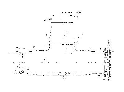
Number 1 in Figure 1 indicates a filter for
filtering fluid, in particular gas. Figure 1 shows
schematically a conduit 2 for supplying a compressor 3
of a petrochemical plant with gas; and filter 1 is
installed along and forms part of conduit 2, and serves
to separate from the gas flow any solid particles that
could damage compressor 3. Filter 1 comprises a tubular
cartridge 4 which extends along a longitudinal axis Al,
filters the gas, and comprises two annular ends 5, 6; a
casing 7 which is connectable to conduit 2, houses
tubular cartridge 4, and comprises two end supports 8,
9; and an axial compensating ring 10 located between
tubular cartridge 4 and end supports 8 and 9. In the
Figure 1 example, axial compenthating ring 10 is located
between annular end 6 and end support 9.
Casing 7 is substantially inverted-T-shaped,

CA 02758141 2011-10-07
WO 2010/116242
PCT/1B2010/000776
extends along axis Al and an axis A2 perpendicular to
axis Al, and comprises a number of tubular members
joined to one another. In the example shown, the tubular
members are welded- to one another, and comprise a
5 central T fitting 11; three reducers 12, 13, 14 welded
to fitting 11; and a tube 15 welded to reducer 12.
Casing 7 also comprises a flange 17 welded to
reducer 14; and a blank flange 18 fitted by screws to
flange 17 and comprising a portion defining end support
9. In Figure 1, end support 8 is defined by a metal ring
welded to tube 15.
Casing 7 has an opening 19 (closed by a bolt not
shown in Figure 1) in the bottommost part of filter 1 to
drain off any condensation; an opening 20, upstream from
tubular cartridge 4, for receiving a first pressure
gauge (not shown); and an opening 21, downstream from
tubular cartridge 4, for receiving a second pressure
gauge (not shown).
Filter 1 comprises a saddle 22 located over opening
19, and which provides for supporting tubular cartridge
4 as it is inserted into and removed from casing 7. In
actual use, and as shown more clearly in Figure 3,
tubular cartridge 4 does not contact saddle 22.
Tubular cartridge 4 can be extracted through flange
17, after removing blank flange 18 from flange 17. For
easy removal of blank flange 18, filter 1 comprises an
arc-shaped arm 23 which, as shown more clearly in Figure
2, supports blank flange 18 and is fitted to casing 7 to

CA 02758141 2011-10-07
WO 2010/116242
PCT/1B2010/000776
6
rotate about a vertical axis A3.
As shown in Figure 2, blank flange 18 also
comprises a handle 24 and two inspection windows 25.
In the Figure 4 variation, tube 15 and end support
8 are replaced with a tube 26, in which an end support
27 is machined, and which has a relatively thick wall
that can be turned internally.
With reference to Figure 7, tubular cartridge 4 is
connected by screws to axial compensating ring 10 to
form a one-piece cartridge-ring assembly.
In the example shown, tubular cartridge 4 comprises
a metal tube 28; and two rings 29, 30 welded to the free
ends of tube 28 to define annular ends 5, 6 of tubular
cartridge 4. Tube 28 comprises a wall 31, in which
constant-diameter holes 32 are formed, as shown more
clearly in Figure 8.
In the Figure 9 variation, wall 31 has holes 33
flaring in the flow direction D, i.e. radially outwards
of tube 28.
In the Figure 10 variation, wall 31 has holes 34,
each of which comprises a first constant-diameter
portion, and a second portion flaring in flow direction
D.
With reference to Figure 7, ring 29 is fixed to the
outside of tube 28, and comprises an annular end face
35; and a toroidal face 36 for ensuring smooth insertion
and removal of the cartridge. Similarly, ring 30
comprises an annular end face 37 and a toroidal face 38.

CA 02758141 2011-10-07
WO 2010/116242
PCT/1B2010/000776
7
Axial compensating ring 10 comprises two rings 39,
40 connected to each other, to slide in a direction
parallel to axis Al (Figure 1), by an elastic connecting
device 41 comprising a number of connecting modules 42
equally spaced along rings 39, 40 and about axis Al
(Figure 1).
Each connecting module 42 comprises a pin 43 fixed
to ring 40 and connected to ring 39 to slide parallel to
axis Al (Figure 1); and an elastic member 44 inserted
between rings 39 and 40 and fitted about pin 43. In
other words, pin 43 is parallel to axis Al (Figure 1),
is screwed inside a threaded hole 45 in ring 40, and is
fitted in sliding manner inside a hole 46 formed in ring
39 and facing hole 45.
Pin 43 comprises an annular groove 47; and
connecting module 42 comprises a retainer 48 which
projects inside hole 46 to engage part of annular groove
47, so that the travel of pin 43 is limited to the
difference between the width of annular groove 47 and
the width of retainer 48. In the Figure 7 example,
retainer 48 is a screw fitted to ring 39 and which
projects inside hole 46, and elastic member 44 is
defined by a series arrangement of Belleville washers.
The size of filter 1 may vary according to the gas
flow rate, which means the size of casing 7 and tubular
cartridge 4 may vary according to project requirements.
Connecting modules 42, on the other hand, remain
unchanged, and only vary in number alongside variations

CA 02758141 2011-10-07
WO 2010/116242
PCT/1B2010/000776
8
in the size of filter 1.
In the Figure 5 variation, ring 29 is replaced with
a ring 49 fixed by screws to tube 28 and comprising a
groove into which the end of tube 28 is inserted; and
the screws are fitted through ring 49 and wall 31 of
tube 28. Ring 49 comprises an end wall 50; a cylindrical
outer wall 51; and a sloping wall 52 defined by a bevel
between end wall 50 and cylindrical outer wall 51.
In the Figure 6 variation, ring 29 is replaced with
a ring 53 welded to wall 31 of tube 28, and comprising
an end wall 54; a cylindrical outer wall 55; and a
sloping wall 56 defined by a bevel between end wall 54
and cylindrical outer wall 55.
With reference to Figure 1, end support 8 and ring
29 comprise respective holes 57 and 58, which, in use,
are aligned to direct any condensation forming inside
tube 15 to opening 19.
Accordingly, tubular cartridge 4 can be oriented
selectively about axis Al by means of two handles 59
fitted to axial compensating ring 10 as shown in Figure
11; and axial compensating ring 10 and casing 7 have
respective reference marks 60, 61 and 62 indicating
given positions - in the example shown, two positions
90 apart - of tubular cartridge 4 with respect to
casing 7, and in one of which two positions the holes 57
and 58 in Figure 1 are aligned.
With reference to Figures 12 and 13, tube 28 has
areas with no holes 32, so as to define, along wall 31

CA 02758141 2011-10-07
WO 2010/116242
PCT/1B2010/000776
9
of tube 28, a solid longitudinal strip 63 parallel to
axis Al, and a solid annular strip 64 about the middle
of tube 28. Because tubular cartridge 4 is self-
supporting, i.e. has no supporting frame, the structural
rigidity of tubular cartridge 4 must be provided by tube
28, which in fact is the purpose of longitudinal strip
63 and annular strip 64. Depending on its size, tube 28
may even comprise numerous longitudinal strips 63 and
annular strips 64.
With reference to Figure 14, tube 28 comprises
three adjacent tubular portions 65, 66, 67, wherein
tubular portion 66 has a higher hole density than
tubular portions 65 and 67, to reduce the turbulence in
filter 1 and so reduce the stress exchanged between
tubular cartridge 4 and casing 7.
With reference to Figure 15, tube 28 has a
downward-facing sector 68; and a predominantly upward-
facing sector 69 with a higher hole density than sector
68. This solution also provides for reducing turbulence
of the fluid, and so reducing stress on tubular
cartridge 4.
In actual use, the fluid is fed into tubular
cartridge 4, and flows out through holes 32; any solid
particles are retained inside tubular cartridge 4; and
any condensation collects at the bottom of casing 7, and
is drained off now and again through opening 19 when the
petrochemical plant is idle.
In actual use, blank flange 18 pre-compresses axial

CA 02758141 2011-10-07
WO 2010/116242
PCT/1B2010/000776
compensating ring 10 against the tubular cartridge, thus
making it possible to compensate for the difference in
thermal expansion, and absorb any shock, between tubular
cartridge 4 and casing 7.
5 Clearly, changes may be made to the present
invention as described herein without, however,
departing from the scope of the accompanying Claims.

Dessin représentatif
Une figure unique qui représente un dessin illustrant l'invention.
États administratifs

2024-08-01 : Dans le cadre de la transition vers les Brevets de nouvelle génération (BNG), la base de données sur les brevets canadiens (BDBC) contient désormais un Historique d'événement plus détaillé, qui reproduit le Journal des événements de notre nouvelle solution interne.

Veuillez noter que les événements débutant par « Inactive : » se réfèrent à des événements qui ne sont plus utilisés dans notre nouvelle solution interne.

Pour une meilleure compréhension de l'état de la demande ou brevet qui figure sur cette page, la rubrique Mise en garde , et les descriptions de Brevet , Historique d'événement , Taxes périodiques et Historique des paiements devraient être consultées.

Historique d'événement

Description Date
Inactive : COVID 19 - Délai prolongé 2020-03-29
Représentant commun nommé 2019-10-30
Accordé par délivrance 2018-01-16
Inactive : Page couverture publiée 2018-01-15
Requête pour le changement d'adresse ou de mode de correspondance reçue 2018-01-12
Préoctroi 2017-11-30
Inactive : Taxe finale reçue 2017-11-30
Lettre envoyée 2017-06-05
Un avis d'acceptation est envoyé 2017-06-05
Inactive : Approuvée aux fins d'acceptation (AFA) 2017-05-26
Inactive : Q2 échoué 2017-05-19
Modification reçue - modification volontaire 2016-12-05
Inactive : Dem. de l'examinateur par.30(2) Règles 2016-06-03
Inactive : Rapport - Aucun CQ 2016-06-03
Lettre envoyée 2015-03-03
Exigences pour une requête d'examen - jugée conforme 2015-02-17
Toutes les exigences pour l'examen - jugée conforme 2015-02-17
Requête d'examen reçue 2015-02-17
Lettre envoyée 2012-06-19
Inactive : Transfert individuel 2012-06-05
Inactive : Page couverture publiée 2011-12-13
Inactive : CIB en 1re position 2011-11-28
Inactive : Notice - Entrée phase nat. - Pas de RE 2011-11-28
Inactive : CIB attribuée 2011-11-28
Demande reçue - PCT 2011-11-28
Exigences pour l'entrée dans la phase nationale - jugée conforme 2011-10-07
Demande publiée (accessible au public) 2010-10-14

Historique d'abandonnement

Il n'y a pas d'historique d'abandonnement

Taxes périodiques

Le dernier paiement a été reçu le 2017-04-03

Avis : Si le paiement en totalité n'a pas été reçu au plus tard à la date indiquée, une taxe supplémentaire peut être imposée, soit une des taxes suivantes :

  • taxe de rétablissement ;
  • taxe pour paiement en souffrance ; ou
  • taxe additionnelle pour le renversement d'une péremption réputée.

Veuillez vous référer à la page web des taxes sur les brevets de l'OPIC pour voir tous les montants actuels des taxes.

Titulaires au dossier

Les titulaires actuels et antérieures au dossier sont affichés en ordre alphabétique.

Titulaires actuels au dossier
SAIPEM S.P.A.
Titulaires antérieures au dossier
PAOLO MINOLA
Les propriétaires antérieurs qui ne figurent pas dans la liste des « Propriétaires au dossier » apparaîtront dans d'autres documents au dossier.
Documents

Pour visionner les fichiers sélectionnés, entrer le code reCAPTCHA :


Pour visualiser une image, cliquer sur un lien dans la colonne description du document. Pour télécharger l'image (les images), cliquer l'une ou plusieurs cases à cocher dans la première colonne et ensuite cliquer sur le bouton "Télécharger sélection en format PDF (archive Zip)" ou le bouton "Télécharger sélection (en un fichier PDF fusionné)".

Liste des documents de brevet publiés et non publiés sur la BDBC .

Si vous avez des difficultés à accéder au contenu, veuillez communiquer avec le Centre de services à la clientèle au 1-866-997-1936, ou envoyer un courriel au Centre de service à la clientèle de l'OPIC.


Description du
Document 
Date
(aaaa-mm-jj) 
Nombre de pages   Taille de l'image (Ko) 
Description 2011-10-07 10 354
Dessins 2011-10-07 5 132
Revendications 2011-10-07 4 191
Abrégé 2011-10-07 1 63
Dessin représentatif 2011-11-29 1 10
Page couverture 2011-12-13 1 39
Dessins 2016-12-05 5 147
Description 2016-12-05 10 351
Revendications 2016-12-05 4 150
Dessin représentatif 2017-12-28 1 15
Page couverture 2017-12-28 1 47
Paiement de taxe périodique 2024-03-26 27 1 099
Avis d'entree dans la phase nationale 2011-11-28 1 194
Courtoisie - Certificat d'enregistrement (document(s) connexe(s)) 2012-06-19 1 103
Rappel - requête d'examen 2014-12-09 1 117
Accusé de réception de la requête d'examen 2015-03-03 1 176
Avis du commissaire - Demande jugée acceptable 2017-06-05 1 164
PCT 2011-10-07 14 490
Demande de l'examinateur 2016-06-03 3 234
Modification / réponse à un rapport 2016-12-05 12 401
Taxe finale 2017-11-30 1 46