Note : Les descriptions sont présentées dans la langue officielle dans laquelle elles ont été soumises.
CA 02758489 2011-11-15
1
FASTENER DRIVING TOOL
[00011 The invention relates to a fastener driving tool, more particularly a
hand-held
fastener driving tool according to the preamble of Claim 1.
[00021 DE 102 60 703 Al describes a liquefied petroleum gas-driven fastener
driving
tool that has a metering chamber with an adjustable metered volume. The
metered volume
can be varied by an electric motor drive, and an ejection of liquefied
petroleum gas into a
combustion chamber is initiated by a pneumatic drive by means of compressed
air.
[00031 The problem of the invention is to specify a fuel-driven fastener
driving tool that
operates simply and reliably.
[00041 This problem is solved for a fastener driving tool of the type
mentioned above by
the characterizing features of Claim 1. The use of the fuel pressure as the
energy source for
driving the displacement member makes an effective and fast transport of the
metered fuel
into the combustion chamber possible in an easy manner.
[00051 This makes it cost-effectively possible to forgo additional drive
mechanisms, such
as electrical and pneumatic drives, for the displacement member. Finally, the
mechanical
energy stored in the fuel tank is intelligently used to enable the metering of
the fuel into the
combustion chamber quickly and precisely.
[00061 A displacement member within the meaning of the invention is understood
to be
any movable component by means of which fuel can be ejected from the metering
space.
[00071 In a preferred embodiment, the displacement member can be constructed
as a
linearly displaceable reciprocating pisto, for example, that is guided in a
cylinder forming the
metering space, at least in part. In this case, the fuel would be directly
forced out of the
metering space by the displacement member. Alternatively, however, the
metering space
itself can be constructed to be variable, for example as a collapsible bellows
or as a volume
with an elastic wall. In such configurations, the displacement member can be
constructed as
an actuating plunger deforming the metering space, for example. In a preferred
embodiment,
the elastic wall itself forms the displacement member, specifically, by
application of pressure
from the side opposite the metering space.
[00081 It is preferably assumed within the meaning of the present invention
that the fuel
is metered predominantly or exclusively in the liquid phase, whereby the
amount of fuel
introduced into the combustion chamber is defined especially precisely. With
liquefied
CA 02758489 2011-11-15
2
petroleum gas as the fuel, such an exclusive metering in the liquid phase can
be ensured, for
example, by arranging a diaphragm in the fuel tank, wherein the liquefied
petroleum gas is
kept exclusively in the liquid phase inside the diaphragm and an inert gas
under a defined
positive pressure is provided outside the diaphragm, for example. As the fuel
is consumed,
the inert gas expands and, due to its positive pressure, keeps the liquefied
petroleum gas in
the liquid phase at all times. Such a conventionally known configuration of a
fuel tank is
accompanied in practice as a matter of course by a certain variation of the
pressure in the fuel
tank as it is being emptied. That constitutes a difference from conventional
storage
containers for liquefied petroleum gas, in which liquefied gas is stored in a
coexistence of
gaseous and liquid phases in a constant volume, and thus provides a constant
pressure.
[00091 In one possible embodiment of the invention it is provided that a drive
unit of the
displacement member comprises a rechargeable mechanical energy accumulator,
with the
energy accumulator being recharged by the pressure of the fuel. In a preferred
detailed
design, the mechanical energy accumulator can comprise a mechanical spring, a
pneumatic
spring or a magnetic spring. This guarantees a particularly defined ejection
process of the
liquid fuel into the combustion chamber. The ejection can preferably be
initiated by simple
opening of a valve. Alternatively or additionally, the mechanical energy
accumulator can
also comprise an additional support device by means of which it can be
triggered.
[00101 In another preferred embodiment of the invention, the displacement
member can
be directly driven by a pressure of the fuel, preferably via a connection to
the fuel tank. This
provides a mechanically simple driving of the displacement member. As also in
the case
where a mechanical intermediate accumulator for the drive energy is used, the
fuel can easily
be ejected from the metering space by opening a valve.
[00111 In an expedient refinement, the displacement member can be held in an
initial
position under a force, preferably but not necessarily by means of a spring.
In a simple
manner, this ensures a defined starting position of the displacement member
before initiation
of the metering process.
[00121 In a generally advantageous detailed design, the metering device
comprises at
least one valve member, the valve member being preferably driven electrically.
The metering
space can preferably be blocked off from the combustion chamber by the valve
member, in
which case the ejection process for the fuel can be triggered by the opening
of this barrier, for
example.
I i
CA 02758489 2011-11-15
3
[0013] Further advantageously, the valve member can be constructed as a three-
way
valve, in particular with two switching positions, in the interest of a simple
and effective
realization. Overall this allows a simple and reliable control of the metering
device. Further
advantageously, the two switching positions of the three-way valve can be
configured as
bistable positions, whereby a particularly low consumption of electric energy
for the valve
member becomes possible.
[0014] In a preferred refinement, the defined quantity of fuel is adjustably
variable, by
means of a variable stop for the displacement member, for example. In this
manner it is
possible to react specifically to changed environmental conditions such as the
ambient
temperature. In particular, the defined quantity of fuel can be increased in
case of a
decreasing ambient temperature in order to be able to provide an ignitable
mixture in the
combustion chamber sufficiently quickly, even when evaporation of the fuel is
retarded.
Depending on requirements, the stop can be adjusted by a thermomechanical
element, e.g., a
bimetallic element or an expansion material element, or by means of an
electrical adjustment
drive, preferably a stepper motor. It is provided in a generally advantageous
manner that a
characteristic curve of the defined fuel quantity as a function of an ambient
temperature has a
substantially bilinear progression.
[0015] This can be advantageously used so that the metered fuel quantity is
varied only in
the low temperature range, for example, while a constant amount of fuel is
metered after
reaching a certain limit temperature, in the range of an ambient temperature
of 20 C for
example.
[0016] Further advantages and characteristics of the invention follow from the
exemplary
embodiments described below, and from the dependent claims.
[0017] Several exemplary embodiments of the invention will be described below
and
explained in detail with reference to the attached drawings.
[0018] Figure 1 illustrates a schematic overall view of a fastener driving
tool according to
the invention.
[0019] Figure 2 illustrates a schematic representation of a first embodiment
of the
invention with a mechanical energy accumulator.
[0020] Figure 3 illustrates a second exemplary embodiment of the invention in
a standby
state of the metering device.
I i
CA 02758489 2011-11-15
4
[0021] Figure 4 illustrates the exemplary embodiment from Figure 3 during a
metering of
the fuel.
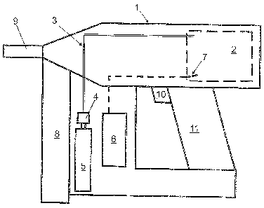
[0022] The fastener driving tool shown schematically in Figure 1 comprises a
housing I
in which a combustion chamber 2 is arranged. Liquefied petroleum gas is stored
as fuel in a
fuel tank 5 and can be injected into the combustion chamber 2 via a line 3.
The line 3
connects a metering device 4 to the combustion chamber 2, the metering device
4 being in
turn connected to a fuel tank 5 arranged in or on the housing 1. In
particular, the fuel tank
can be constructed as a replaceable cartridge.
[0023] The fastener driving tool further comprises an electronic controller 6
with an
electrical storage battery as the energy accumulator. The electronic
controller 6 controls a
spark plug 7 in the combustion chamber 2, and optionally the metering device 4
as well, if the
latter has electric valves or other electrically controlled components. A
magazine 8 for
storing fastening means such as nails is arranged in an anterior area of the
driving tool. A
contact member 9 can be pressed against a workpiece in order to enable
triggering of the
fastener driving tool.
[0024] A fastening member from the magazine 8 is driven in by the ignition of
a liquid
petroleum gas-air mixture in the combustion chamber 2 by means of the spark
plug 7, after
which a piston (not shown) is driven forward and drives the fastening member
or the nail into
the workpiece via a driving plunger (not shown). This driving process is
initiated by an
operator via a switch 10, which is arranged in a handle area 11 of the housing
1 in this case.
[0025] Figure 2 shows a first exemplary embodiment of the metering device 4.
The
metering device 4 comprises a metering space 12 that is connected via a three-
way valve 18
with two switching positions 18 firstly to the fuel tank 5 via a feed line
18a, and secondly to
the combustion chamber 2 via a feed line 18b. A valve slide 19 is arranged in
a slide
chamber that is part of the metering space 12. A third feed line 18c connects
the slide
chamber 12 to a cylindrical space 17 in which a displacement member 16 in the
form of a
reciprocating piston is guided. The space 17 forms an additional part of the
metering space
12, wherein a movement of the displacement member 16 into the space 17 can
eject the fuel
located therein. Figure 2 shows the displacement member 16 in the position
maximally
advanced into the cylinder 17.
[0026] The valve slide 19 is electrically actuated and can assume two defined
positions.
In the first position, which is shown in Figure 2, the feed line 18a is closed
and the feed line
CA 02758489 2011-11-15
l 8b is opened. In the other position, not shown, the feed line 18a is opened
and the feed line
18b is closed. The connection 18c between the slide chamber and the cylinder
17 is
permanently opened.
[0027] Depending on requirements, the positions of the valve slide 19 can each
be stable
positions (bistable valve slide) so that only a short electrical pulse
requiring little energy is
necessary to change the valve over. In another embodiment, the valve slide 19
is always
arranged in a de-energized rest position, i.e., closing the connection 18b to
the combustion
chamber 2 (monostable valve slide). By applying an electrical voltage, the
valve slide is
brought into the opposite position (see Figure 2), in which it closes the
connection 18a to the
fuel tank 5.
[0028] The reciprocating piston, or displacement member, 16 is subjected to
force in the
ejection direction by means of a spring 21, a helical spring in the present
case.
[0029] In the direction opposite to the ejection direction or the force of the
spring 21, the
path of the reciprocating piston 16 is limited by an adjustable stop 15. The
stop 15 is
constructed as a linearly adjustable pin that can be connected, for example,
to a
thermomechanical element or an electrical adjustment device. The stop 15 can
project further
at higher ambient temperatures and thus reduce the possible stroke of the
reciprocating piston
16, and can enlarge it at lower temperatures. In this way a defined quantity
of fuel,
determined by the stroke of the displacement member 16 in the cylinder 17, can
be varied
specifically.
[0030] The reciprocating piston 16 is slidingly guided in a seal 16a, so that
its end facing
the spring 21 is under ambient pressure, the seal 16a forming a barrier
between the liquefied
petroleum gas and the surroundings. Alternatively to a sliding seal, a
different type of seal,
for example a closed bellows, can also be selected.
[0031] The metering device according to Figure 2 functions as follows:
[0032] Initially, the valve member 18 is brought by means of the controller 6
into the
position, not shown, in which the slide chamber 12 is connected to the fuel
tank and the
combustion chamber is disconnected from the metering space 12. Liquefied
petroleum gas
can then flow in the liquid phase into the metering space 12 adjusted with the
stop 15.
[0033] The liquefied petroleum gas in tank 5 is present only in the liquid
phase. This is
accomplished in a conventional manner by enclosing the liquefied petroleum gas
in the tank
in a diaphragm and filling the area outside the diaphragm with an inert gas
under a pressure
CA 027584189 2011-11-15
6
higher than the vapor pressure of the liquefied petroleum gas. Due to this
positive pressure,
no evaporation process takes place following the flowing of the liquefied
petroleum gas into
the metering space 12, so that there is substantially no change of temperature
following the
flowing of the liquid gas.
[0034] The inflowing liquefied petroleum gas presses the reciprocating piston
16 upwards
(in the representation Figure 2) as far as the stop 15 against the force of
the spring 21, while
filling up the free part of the cylinder 17 as metering space 12. In this
upper position, the
metering device is in readiness to eject the fuel into the combustion chamber.
The spring 21
is tensioned, interim-storing mechanical energy that was removed from the
pressurized fuel
tank during the movement of the reciprocating piston 17.
[0035] If the fastener driving tool is triggered by actuating the switch 10,
the valve slide
19 is changed over by means of the controller 6. In the process, the feed line
18a is closed
and the feed line l8b is opened (see position in Figure 2). Thus the liquefied
petroleum gas
flows into the combustion chamber 2, driven by its vapor pressure in addition
to the spring
force of the spring 21, which rapidly pushes the displacement member 16
downward into the
cylinder 17 filled with liquefied petroleum gas.
[0036] The amount of liquid metered into the combustion chamber 2, depending
on the
adjustment of the stop 15, is larger at lower temperatures so that, even with
a slower
evaporation and/or a higher oxygen concentration in the combustion chamber, an
ignitable
mixture is provided in the combustion chamber 2 sufficiently quickly.
[0037] Then the liquid petroleum gas-air mixture can be ignited in the
combustion
chamber in the conventional manner.
[0038] Figures 3 and 4 show a second exemplary embodiment of the invention. An
essential difference from the previous exemplary embodiment is that the
liquefied petroleum
gas is not ejected from the metering space 12 by means of a chargeable energy
accumulator
(spring 21), but instead directly by the pressure of the fuel.
[0039] Just as in the preceding embodiment, the displacement member 16 is
constructed
as a linearly movable piston located in a cylinder 17 that is part of the
metering space 12.
The cylinder 17 encloses a fixed volume 12 that is connected to or cut off
from the fuel tank
and the combustion chamber 2 via respective discrete valve members 13, 14. In
the
standby position of Figure 3, the valve 13 for connecting to the fuel tank is
opened and the
valve 14 for connecting to the combustion chamber 14 is closed.
I I
CA 02758489 2011-11-15
7
[00401 A branch line 20 leads from the connection of the fuel tank 5 and valve
member
13 to an end of the cylinder 17 facing away from the valve members 13, 14. The
branch line
20 connects an upper end of the piston-like displacement member 16 to the fuel
tank 5.
[00411 An adjustment mechanism 15a by which the upper stop 15 for the
displacement
member 16 can be adjusted, depending in particular on the temperature, the air
pressure, the
gas pressure and/or the gas bottle fill level, is also arranged in this upper
end area of the
cylinder 17.
[00421 The piston 16 is also tensioned by means of a spring (not shown) into
its upper
stop position in the direction of the force FV, which is symbolized by the
upward-directed
arrow in Figure 3. In this starting position according to Figure 3, the
pressure of the fuel tank
is present in the cylinder 17 both above and below the piston 16. The spring
force only
serves to provide a defined positioning of the piston 16 in a starting
position. The force of
the positioning spring can accordingly be relatively small.
[00431 A triggering process for the fastener driving tool takes place by
changing over the
valves 13, 14 to the respective opposite position. Thereby the lower part of
the cylinder 17
and the fixed part of the metering space 12, which is connected to the valve
14, are connected
to the combustion chamber 2, in which there is a considerably lower pressure
(ambient
pressure). Above the piston 16, the cylinder 17 is subjected via the line 20
to the pressure in
the fuel tank 5. Thereby the piston 16 is accelerated downwards according to
the drawings,
or in the direction of the fixed space 12, pressing the liquefied petroleum
gas out of the lower
part of the cylinder 17 into the combustion chamber 2. After this process, the
piston 16 has
reached a lower stop position shown in Figure 4. According to this process,
the displacement
member 16 is driven directly by the pressure of the fuel in the tank 5.
100441 For clarity, the volume areas in which the liquefied petroleum gas is
in
equilibrium in the liquid phase or under high-pressure are shown in Figures 3
and 4 with
crosshatching.
[00451 It is understood that, depending on requirements, it is possible in
each of the
above-described exemplary embodiments to provide either a discrete arrangement
of two
valves (13, 14 in Figure 3) or the arrangement of a three-way valve (18 in
Figure 2) with two
switching positions.