Sélection de la langue

Search

Sommaire du brevet 2758598 

Énoncé de désistement de responsabilité concernant l'information provenant de tiers

Une partie des informations de ce site Web a été fournie par des sources externes. Le gouvernement du Canada n'assume aucune responsabilité concernant la précision, l'actualité ou la fiabilité des informations fournies par les sources externes. Les utilisateurs qui désirent employer cette information devraient consulter directement la source des informations. Le contenu fourni par les sources externes n'est pas assujetti aux exigences sur les langues officielles, la protection des renseignements personnels et l'accessibilité.

Disponibilité de l'Abrégé et des Revendications

L'apparition de différences dans le texte et l'image des Revendications et de l'Abrégé dépend du moment auquel le document est publié. Les textes des Revendications et de l'Abrégé sont affichés :

  • lorsque la demande peut être examinée par le public;
  • lorsque le brevet est émis (délivrance).
(12) Brevet: (11) CA 2758598
(54) Titre français: ENSEMBLE ELARGISSEUR A JET
(54) Titre anglais: JETTED UNDERREAMER ASSEMBLY
Statut: Périmé et au-delà du délai pour l’annulation
Données bibliographiques
(51) Classification internationale des brevets (CIB):
  • E21B 10/32 (2006.01)
(72) Inventeurs :
  • ERIKSEN, ERIK P. (Canada)
(73) Titulaires :
  • SCHLUMBERGER CANADA LIMITED
(71) Demandeurs :
  • SCHLUMBERGER CANADA LIMITED (Canada)
(74) Agent: BORDEN LADNER GERVAIS LLP
(74) Co-agent:
(45) Délivré: 2015-06-23
(86) Date de dépôt PCT: 2010-04-14
(87) Mise à la disponibilité du public: 2010-10-21
Requête d'examen: 2012-10-24
Licence disponible: S.O.
Cédé au domaine public: S.O.
(25) Langue des documents déposés: Anglais

Traité de coopération en matière de brevets (PCT): Oui
(86) Numéro de la demande PCT: 2758598/
(87) Numéro de publication internationale PCT: CA2010000574
(85) Entrée nationale: 2011-10-13

(30) Données de priorité de la demande:
Numéro de la demande Pays / territoire Date
12/423,481 (Etats-Unis d'Amérique) 2009-04-14

Abrégés

Abrégé français

L'invention porte sur un élargisseur pour des opérations de forage de terre, lequel élargisseur comprend un corps tubulaire avec un passage s'étendant à travers celui-ci. Des bras sont montés de façon à pouvoir pivoter sur le corps, et sont mobiles entre des positions rétractée et étendue. Un mandrin d'actionneur, disposé à l'intérieur du passage dans le corps, pousse les bras vers l'extérieur lorsqu'un fluide de forage est pompé vers le bas dans le train de tiges de forage. Des orifices sont situés dans la paroi latérale du corps et dans le mandrin d'actionneur. Les orifices s'alignent entre eux lorsque le mandrin se déplace vers sa position avale. Les orifices font dévier une partie du fluide de forage vers l'extérieur de façon à l'éjecter sur les éléments de coupe sur les bras. La partie restante du fluide de forage passe vers le bas, vers le trépan, et vers l'extérieur des buses du trépan.


Abrégé anglais


An underreamer for earth boring operations has a tubular body with a passage
extending through it. Arms are pivotally mounted to the body and movable
between retracted
and extended positions. An actuator mandrel, located within the passage in the
body, pushes
the arms outward when drilling fluid is pumped downward in the drill string.
Ports are
locat-ed in the sidewall of the body and in the actuator mandrel. The ports
align with each other
when the mandrel moves to its downstream position. The ports divert a portion
of the drilling
fluid out to jet it across the cutting elements on the arms. The remaining
portion of the
drilling fluid passes downward to the drill bit and out nozzles of the drill
bit.

Revendications

Note : Les revendications sont présentées dans la langue officielle dans laquelle elles ont été soumises.


CLAIMS:
1. An apparatus for earth boring, comprising:
a tubular body having one end for securing to a drill string and another end
for
securing to a drill bit;
a passage extending through the body along a longitudinal axis of the body;
a plurality of arms pivotally mounted to the body and movable between a
retracted position and an extended position, each of the arms having a face
containing a plurality of cutting elements mounted thereon;
an actuator mandrel carried in the passage, the actuator mandrel being axially
movable from an upstream position to a downstream position in response to
drilling
fluid being pumped down the drill string, the actuator mandrel being
cooperatively
engaged with the arms for moving the arms to the extended position when the
actuator mandrel moves to the downstream position;
a plurality of body ports extending through a sidewall of the body, each body
port being adjacent the face of one of the arms when the arms are in the
extended
position;
a plurality of mandrel ports extending through a sidewall of the mandrel, each
of the mandrel ports being axially offset from one of the body ports while the
mandrel
is in the upstream position and aligned with one of the body ports while the
mandrel
is in the downstream position for discharging a portion of the drilling fluid
across the
face of one of the arms;
a liner located within and axially movable with the mandrel, the liner being
formed of a more wear resistant material than the mandrel; and
wherein the mandrel ports extend through the liner.
2. The apparatus according to claim 1, further comprising:
a nozzle of a wear resistant material secured within each of the mandrel
ports.
-9-

3. The apparatus according to claim 1, wherein the mandrel ports and the
body
ports incline relative to the axis of the body.
4. The apparatus according to claim 1, wherein:
each of the arms has an innermost one of the cutting elements and an
outermost one of the cutting elements; and
wherein a centerline of each of the body ports is aligned with the outermost
one of the cutting elements on one of the arms when the arms are in the
extended
position.
5. The apparatus according to claim 1, wherein a centerline of each of the
mandrel ports is at an angle relative to a radial line passing from the
longitudinal axis
through the same mandrel port.
6. The apparatus according to claim 1, wherein:
the mandrel ports have outlets and the body ports have inlets that register
with
each other while the mandrel is in the downstream position.
7. The apparatus according to claim 1, further comprising:
a piston on the mandrel that seals to and engages an interior portion of the
body; and
a vent port through the sidewall of the body below the piston and above the
arms.
8. An apparatus for earth boring, comprising:
a tubular body having one end for securing to a drill string and another end
for
securing to a drill bit;
a body passage extending through the body along a longitudinal axis of the
body;
a plurality of arms pivotally mounted to the body and movable between a
retracted position and an extended position, each of the arms having a face
-10-

containing a plurality of cutting elements mounted thereon, the cutting
elements
comprising flat disks;
an actuator mandrel carried in the passage and having a mandrel passage
axially aligned with the body passage;
a piston on the mandrel that slidingly and sealingly engages an inner diameter
portion of the body, the piston axially moving the mandrel from an upstream
position
to a downstream position in response to drilling fluid being pumped down the
drill
string;
rack and pinion gear teeth formed on the mandrel and each of the arms for
moving the arms to the extended position when the actuator mandrel moves to
the
downstream position;
a plurality of body ports extending through a sidewall of the body at an
inclination relative to the axis, each body port having an inlet in the body
passage
and an outlet adjacent the face of one of the arms when the arms are in the
extended
position;
a plurality of mandrel ports extending through a sidewall of the mandrel at an
inclination relative to the axis, each of the mandrel ports having an inlet in
the
mandrel passage and an outlet that registers with the inlet of one of the body
ports
while the mandrel is in the downstream position;
a nozzle of a wear resistant material located within each of the mandrel
ports;
a liner located within and axially movable with the mandrel, the liner being
formed of
a more wear resistant material than the mandrel; and
wherein the mandrel ports extend through the liner.
9. An apparatus for earth boring, comprising:
a tubular body having one end for securing to a drill string and another end
for
securing to a drill bit;
-11-

a body passage extending through the body along a longitudinal axis of the
body;
a plurality of arms pivotally mounted to the body and movable between a
retracted position and an extended position, each of the arms having a face
containing a plurality of cutting elements mounted thereon, the cutting
elements
comprising flat disks;
an actuator mandrel carried in the passage and having a mandrel passage
axially aligned with the body passage;
a piston on the mandrel that slidingly and sealingly engages an inner diameter
portion of the body, the piston axially moving the mandrel from an upstream
position
to a downstream position in response to drilling fluid being pumped down the
drill
string;
rack and pinion gear teeth formed on the mandrel and each of the arms for
moving the arms to the extended position when the actuator mandrel moves to
the
downstream position;
a plurality of body ports extending through a sidewall of the body at an
inclination relative to the axis, each body port having an inlet in the body
passage
and an outlet adjacent the face of one of the arms when the arms are in the
extended
position;
a plurality of mandrel ports extending through a sidewall of the mandrel at an
inclination relative to the axis, each of the mandrel ports having an inlet in
the
mandrel passage and an outlet that registers with the inlet of one of the body
ports
while the mandrel is in the downstream position;
a nozzle of a wear resistant material located within each of the mandrel
ports;
and
wherein a centerline extending through each of the mandrel ports will coincide
with a centerline of one of the body ports while the mandrel is in the
downstream
position.
-12-

10. The apparatus according to claim 9, wherein:
each of the arms has an outermost one of the cutting elements; and
wherein a centerline of each of the body ports aligns with the outermost one
of
the cutting elements on one of the arms when the arms are in the extended
position.
11. The apparatus according to claim 9, wherein a centerline of each of the
body
ports is substantially parallel with the face of one of the arms when the arms
are in
the extended position.
12. The apparatus according to claim 9, wherein:
a vent port extends through the sidewall of the body below the piston.
13. An apparatus for earth boring, comprising:
a string of casing adapted to be rotated to form a borehole;
a retrievable bottom hole assembly having a latch assembly that latches the
bottom hole assembly to the string of casing for rotation therewith, the
bottom hole
assembly extending below the string of casing;
a drill bit at a lower end of the bottom hole assembly for forming a pilot
hole in
the wellbore;
an underreamer in the bottom hole assembly between the drill bit and the
string of casing, the underreamer having a plurality of arms extending outward
therefrom to a diameter greater than an outer diameter of the string of
casing, each of
the arms having a face containing a plurality of cutting elements mounted
thereon for
enlarging the pilot hole;
a longitudinal passage extending through the underreamer for delivering
drilling fluid pumped down the string of casing to the drill bit;
a plurality of ports in the underreamer, leading from the passage to an
exterior
of the underreamer, each of the ports being aligned with the face of one of
the arms
for diverting a portion of the drilling fluid across the face; and
-13-

wherein each of the ports is at an angle relative to a radial line of a
longitudinal
axis of the passage that passes through the same port.
14. The apparatus according to claim 13, wherein:
each of the ports inclines relative to an axis of the passage.
15. The apparatus according to claim 13, further comprising:
an actuator mandrel carried in the passage and movable from an upstream
position to a downstream position in response to drilling fluid being pumped
down the
drill string, the actuator mandrel being cooperatively engaged with the arms
for
moving the arms to the extended position when the actuator mandrel moves to
the
downstream position; and
a plurality of holes extending through a sidewall of the mandrel, each of the
holes being aligned with one of the ports while the mandrel is in the
downstream
position for delivering a portion of the drilling fluid to the ports.
16. The apparatus according to claim 15, further comprising a nozzle
mounted
within each of the holes.
17. The apparatus according to claim 13, wherein a centerline of each of
the ports
circumferentially lags a radial line of a longitudinal axis of the passage,
the radial line
passing through the same port, considering the direction of rotation of the
apparatus.
-14-

Description

Note : Les descriptions sont présentées dans la langue officielle dans laquelle elles ont été soumises.


CA 02758598 2011-10-13
WO 2010/118526 PCT/CA2010/000574
JETTED UNDERREAMER ASSEMBLY
Field of the Invention:
This invention relates in general to earth boring tools, and in particular to
an underrearner
located above a drill bit that has ports for diverting to the cutters on the
underrearner arms some
of the drilling fluid being pumped down the drill string.
Background of the Invention:
Underrearners are employed in well drilling operations to enlarge a pilot
hole. In casing
drilling, the drill string is made up of the casing that will be eventually
cemented in the well. If
i o the drill bit is retrievable, it will be part of a bottom hole assembly
that latches to a collar or
profile sub located near the bottom of the string of casing. The bottom hole
assembly extends
below the string of casing, and the drill bit is on its lower end for drilling
a pilot hole. The
underreamer is located above the drill bit for enlarging the pilot hole to an
outer diameter greater
than the outer diameter of the string of casing.
The underreamer has arms that are pivotally mounted to the body of the
underreamer for
moving between retracted and extended positions. Cutters, typically
polycrystalline diamond
disks, are mounted to the leading face of each ann. One type of underreamer
has an actuator
mandrel carried in its longitudinal passage, the actuator mandrel being
axially movable from an
upstream position to a downstream position in response to drilling fluid being
pumped down the
drill string. The actuator mandrel is cooperatively engaged with the arms for
moving the arms to
an extended position when the actuator mandrel moves to the downstream
position.
The string of casing is rotated by a casing gripper and a top drive of the
drilling rig. The
bottom hole assembly may include a drill motor that rotates the underreamer
and the drill bit

CA 02758598 2011-10-13
WO 2010/118526 PCT/CA2010/000574
independently of the casing string. During drilling, drilling fluid is pumped
down the casing
string, through the bottom hole assembly and out nozzles of the drill bit. The
drilling fluid flows
back up the borehole past the underreamer and up the annulus surrounding the
string of casing.
The drilling fluid removes cuttings and provides lubrication and cooling of
the drill bit and
underreamer, Nevertheless, in some formations, the cutters on the underreamers
arms can
become clogged with cuttings and operate at elevated temperatures. Elevated
temperatures may
be detrimental to the performance and the resistance to abrasion.
Summary of the Invention:
In this invention, the underreamer has an actuator mandrel carried in its
longitudinal
passage, the actuator mandrel being axially movable from an upstream position
to a downstream
position in response to drilling fluid being pumped down the drill string. The
actuator mandrel is
cooperatively engaged with the arms for moving the arms to an extended
position when the
actuator mandrel moves to the downstream position.
A body port for each ann extends through the sidewall of the underreamer body,
each
body port being adjacent the face of one of the arms when the arms are in the
extended position.
Mandrel ports extend through the sidewall of the mandrel. The mandrel ports
are spaced above
the body ports while the mandrel is in the upstream position. The mandrel
ports align with the
body ports when the mandrel is in the downstream position. Preferably an
abrasion resistant
nozzle forms or is mounted in each of the mandrel ports.
Brief Descriptions and Drawings:
Figure 1 is a schematic sectional view illustrating a casing drilling string
and bottom hole
assembly constructed in accordance with this invention.
-2-

CA 02758598 2011-10-13
WO 2010/118526 PCT/CA2010/000574
Figure 2 is enlarged sectional view of the underreamer of the bottom hole
assembly of
Figure 1.
Figure 3 is a further enlarged view of a portion of the underreamer of Figure
2, showing
an arm in the extended position.
Figure 4 is a view of the underreamer similar to Figure 3, but showing the arm
in a
retracted position.
Figure 5 is a sectional view of the underreamer of Figure 2, taken along the
line 5-5 of
Figure 4.
Figure 6 is a sectional view of the underreamer of Figure 2, taken along the
line 6-6 of
Figure 4.
Detailed Description of Invention:
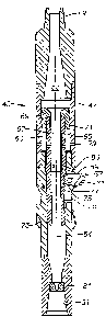
Referring to Fig. 1, a top drive 11 of a drilling rig is schematically shown.
Top drive 11
moves upward and downward in a derrick (not shown) and comprises a rotary
power source
having a quill 13 that rotates. A casing gripper 15 is attached to quill 13
for rotation with it.
Casing gripper 15 has gripping members that engage either the inner diameter
as shown or the
outer diameter of conventional casing 17. Casing string 17 is shown extending
from casing
gripper 15 through a rig floor 19 into a borehole 21.
A bottom hole assembly 22 is releasably secured to casing string 17 near its
lower end.
Bottom hole assembly 22 includes a drill lock assembly ("DLA") 23, which is
shown attached to
a tubular collar or profile sub 25 secured into a lower end portion of casing
string 17. In this
example, DLA 23 has a tubular housing 27. Spring-biased stop dogs 29 extend
out from housing
27 and land on an upward-facing shoulder 31 formed in profile sub 25. DLA 23
also has a set of
torque keys 33 for transmitting torque between profile sub 25 and DLA 23.
Torque keys 33 are
-3-

CA 02758598 2011-10-13
WO 2010/118526 PCT/CA2010/000574
also biased outward by springs in this embodiment and engage mating
longitudinal slots in
profile sub 25. In this embodiment, DLA 23 also has a set of axial lock
members 35. Lock
members 35 engage mating recesses in profile sub 25 to prevent upward movement
of DLA 23
relative to profile sub 25.
DLA 23 has an upper seal 37 on its exterior arranged for preventing the upward
flow of
fluid from below. Upper seal 37 may be a downward facing cup seal. DLA 23 may
also have
one or more lower seals 39 (two shown) for preventing drilling fluid pumped
down from above
from flowing around the exterior of DLA 23. Lower seals 39 may also be cup
seals but face
upward rather than downward. Seals other than cup seals may be employed for
seals 37, 39.
Bottom hole assembly 22 has a drill bit 43 at its lower end. Drill bit 43 may
be any
conventional drag blade type or a rolling cone type. An underreamer 45 is
located in bottom
hole assembly 22 above drill bit 43 and below the lower end of casing string
17. Bottom hole
assembly 22 may also include a drill motor, logging tools, and steering
equipment.
Referring to Fig. 2, underreamer 45 has a tubular body 47 that is made up of
several
components in this example. Body 47 has an upper threaded end 49 and a lower
threaded end
51. Upper threaded end 49 attaches to other structure in bottom hole assembly
22, and lower
threaded end 51 attaches to drill bit 43. A longitudinal passage 53 extends
through body 47 for
transmitting drilling fluid pumped from the drilling rig down casing string
17. Body 47 and
passage 53 have a longitudinal axis 54.
Body 49 has a plurality of axially extending slots 55 formed in its sidewall.
In this
example there are three identical slots 55, each spaced about 120 degrees
apart from the other
around the circumference of body 47, as shown in Fig 5. Each slot 55 extends
from longitudinal
passage 53 to the exterior of body 47. An arm 57 is pivotally secured within
each slot 55 for
-4-

CA 02758598 2011-10-13
WO 2010/118526 PCT/CA2010/000574
movement between a retracted position (Fig. 4) and an extended position (Fig.
3). Ann 57 has a
hole in an upper end through which a pivot pin 59 extends. Pivot pin 59 is
secured within mating
holes of body 47 on opposite sides of slot 55 to enable ann 57 to pivot
between the extended
position and the retracted position. Arm 55 has a forward-facing face,
considering the direction
of rotation, containing cutting elements 61. Preferably cutting elements 61
comprise
polycrystalline diamond disks ("PDC"), each having a flat face that faces into
the direction of
rotation. This example shows three cutting elements 61 on each arm 57, but the
number could
differ.
An actuator mandrel 63 is carried within passage 53. Mandrel 63 has a mandrel
passage
to 65 extending through it that is co-axial with passage 53. Preferably, a
liner 67 is located within
at least an upper portion of passage 65. Liner 67 is formed of a hard, more
wear resistant
material than mandrel 63. Mandrel 63 is typically formed of steel, while liner
67 may be formed
of tungsten carbide, for example. An annular piston 69 is secured to the upper
end of mandrel
63. Piston 69 has seals 71 on its exterior that seal and slidingly engage a
cylindrical portion of
passage 53. Mandrel 63 also has seals 73 on its lower end that seal and
slidingly engage a
smaller diameter portion of passage 53. Piston 69 is located above slots 55,
and seals 73 are
located below slots 55.
Mandrel 63 has a set of rack teeth 75 formed on its exterior adjacent arms 57.
Rack teeth
75 extend in a straight line axially along mandrel 63. Each arm 57 has an
array of gear teeth 77
formed in a partially circular array that mate with rack teeth 75. Pumping
drilling fluid
downward through passage 53 creates a pressure drop within mandrel passage 65
that causes
mandrel 63 to move downward to the downstream position shown in Fig. 2,
thereby pivoting
arms 57 to the extended position. In the extended position, arms 57 will
circumscribe an outer
-5-

CA 02758598 2011-10-13
WO 2010/118526 PCT/CA2010/000574
diameter that is greater than the outer diameter of casing string 17 (Fig. 1).
When the drilling
fluid pressure ceases and the operator pulls upward, anus 57 will move back to
the retracted
position to enable underreamer 45 to be pulled upward into the lower end of
casing 17. Piston
69 moves back to the upstream position shown in Fig. 4.
The annular space surrounding mandrel 63 between piston seal 71 and mandrel
seal 73 is
not a closed chamber rather, rather it has a vent port 79 to allow fluid below
piston 69 to be
displaced out as piston 69 moves downward. It is not necessary that an
exterior portion of
mandrel 63 form a tight seal to the inner diameter of body 47 below vent port
79 and above slots
55. However, the minimum clearance between mandrel 63 and the interior of body
47 just
i o above arms 57 is quite small.
A nozzle 81 may be located near lower threaded end 51 within passage 53.
Nozzle 81
results in a pressure drop to assist in the movement of piston 69 to the lower
position. After
passing through nozzle 81, the drilling fluid will pass through nozzles of
drill bit 43 (Fig. 1).
Referring to Figs. 3 and 4, a body port 83 extends through the sidewall of
underreamer
body 47 for each of anus 57. Body port 83 has its inlet in communication with
passage 53 and
an outlet at the exterior of body 47. Each body port 83 is preferably inclined
downward along
longitudinal axes 54 of body 47, with the inlet located above the outlet. The
amount of
inclination may vary and, in this example, is about 30 degrees relative to a
plane perpendicular to
longitudinal axis 54.
A mandrel port 85 extends through the sidewall of mandrel 63 for registering
with each
body port 83 while mandrel 63 is in the downstream position shown in Fig. 3.
Each mandrel port
85 is inclined relative to longitudinal axis 54 the same amount as each body
port 83. If a liner 67
is employed, holes 87 will be formed through liner 67 for aligning with and
serving as the inlets
-6-

CA 02758598 2011-10-13
WO 2010/118526 PCT/CA2010/000574
of mandrel ports 85. Preferably a nozzle 89 of hard, wear resistant material
such as tungsten
carbide is secured in mandrel port 85. Nozzle 89 is located at the inlet end
of mandrel port 85 in
this example. If mandrel 63 has a fairly thin wall construction, nozzle 89 may
extend from the
inlet to the outlet of mandrel port 85. In that instance, the passage through
nozzle 89 becomes
the mandrel port 85. The outlet of each mandrel port 85 will register with the
inlet of one of the
body ports 83 while mandrel 63 is in the downstream position as shown in Fig.
3. When mandrel
63 is in the upstream position shown in Fig. 4, the outlet of each mandrel
port 85 will be spaced
axially above the inlets of body ports 83. Optionally, there are no seals
between the outlets of
mandrel ports 85 and the inlets of body ports 83. Because of the internal
configuration of nozzle
89, it will cause convergence of the flow stream from the mandrel passage 65
into body port 83
without significant leakage between mandrel 63 and the interior of body 47.
Referring to Fig. 3, a center line 93 of ports 83 and 85 when aligned, will
pass across the
flat face of the outermost cutting element 61, and will be slightly upstream
from cutting elements
61 located inward of the outermost cutting element 61. However, the jetted
spray diverges from
port 83 so that some of it will sweep across the other cutting elements 61.
The outermost cutting
element 61 is typically the hottest during operation because it travels the
greatest circumferential
distance. Aligning centerline 93 with the outermost cutting element 61 assures
that cooling fluid
and lubrication will be provided. The alignment of the center line 93 with the
cutting elements 61
can be varied.
Referring to Fig. 6, in this example, nozzles 89 do not point along radial
lines from
longitudinal axis 54 of mandrel passage 65; rather centerline 93 of each
nozzle 89 is at an angle
to the radial line 95 that passes through the same nozzle 89. Centerline 93
thus does not intersect
longitudinal axis 54. Considering the direction of rotation to be in indicated
by the arrow in Fig.
-7-

CA 02758598 2011-10-13
WO 2010/118526 PCT/CA2010/000574
6, each centerline 93 lags a radial line 95 that passes through the same
nozzle 89. Each an-n 57
does have a center point that would be on a radial line 95. However, the face
of each arm 57, is
not on a radial line 95 from axis 54, rather it is rotationally forward of the
radial line. Nozzles 89
are oriented so that each centerline 93 is substantially parallel and spaced a
short distance
forward from the face of each an-n 57. This orientation causes the jet spray
to sweep across the
faces of cutting elements 61 (Fig. 3).
In operation and referring to Fig. 1, bottom hole assembly 22 is secured to
profile sub 25
for rotational and axial movement by dogs 29 and torque keys 33. Casing string
17 is lowered to
the bottom of borehole 21. The operator operates top drive 11 to rotate casing
string 17 and
pumps drilling fluid down casing string 17, which flows into the upper end of
bottom hole
assembly 22. The drilling fluid pressure pushes piston 69 (Fig. 2) downward,
moving anus 57 to
the extended position. Some of the drilling fluid is jetted out ports 85 and
83 and discharges
across cutting elements 61 of each an-n 57. The remaining drilling fluid flows
out nozzles of drill
bit 43 and back up around anus 57 and casing string 17 to the surface. The
drilling fluid being
jetted out ports 85 and 83 provides cooling, lubrication, and cleaning for
cutting elements 61 of
underrearner anus 57.
While the invention has been shown in only one of its forms, it should be
apparent to
those skilled in the art, that it is not so limited but is susceptible to
various changes without
departing from the scope of the invention.
-8-

Dessin représentatif
Une figure unique qui représente un dessin illustrant l'invention.
États administratifs

2024-08-01 : Dans le cadre de la transition vers les Brevets de nouvelle génération (BNG), la base de données sur les brevets canadiens (BDBC) contient désormais un Historique d'événement plus détaillé, qui reproduit le Journal des événements de notre nouvelle solution interne.

Veuillez noter que les événements débutant par « Inactive : » se réfèrent à des événements qui ne sont plus utilisés dans notre nouvelle solution interne.

Pour une meilleure compréhension de l'état de la demande ou brevet qui figure sur cette page, la rubrique Mise en garde , et les descriptions de Brevet , Historique d'événement , Taxes périodiques et Historique des paiements devraient être consultées.

Historique d'événement

Description Date
Le délai pour l'annulation est expiré 2018-04-16
Lettre envoyée 2017-04-18
Accordé par délivrance 2015-06-23
Inactive : Page couverture publiée 2015-06-22
Inactive : Taxe finale reçue 2015-03-31
Préoctroi 2015-03-31
Lettre envoyée 2014-11-05
Inactive : Transferts multiples 2014-10-24
Un avis d'acceptation est envoyé 2014-10-02
Lettre envoyée 2014-10-02
Un avis d'acceptation est envoyé 2014-10-02
Inactive : Approuvée aux fins d'acceptation (AFA) 2014-06-27
Inactive : Q2 réussi 2014-06-27
Modification reçue - modification volontaire 2014-05-16
Modification reçue - modification volontaire 2014-04-07
Inactive : Dem. de l'examinateur par.30(2) Règles 2013-10-07
Inactive : Rapport - Aucun CQ 2013-09-26
Lettre envoyée 2012-11-06
Requête d'examen reçue 2012-10-24
Exigences pour une requête d'examen - jugée conforme 2012-10-24
Toutes les exigences pour l'examen - jugée conforme 2012-10-24
Inactive : Correspondance - PCT 2012-03-28
Inactive : Page couverture publiée 2011-12-19
Inactive : CIB en 1re position 2011-12-01
Inactive : Notice - Entrée phase nat. - Pas de RE 2011-12-01
Inactive : CIB attribuée 2011-12-01
Demande reçue - PCT 2011-12-01
Exigences pour l'entrée dans la phase nationale - jugée conforme 2011-10-13
Demande publiée (accessible au public) 2010-10-21

Historique d'abandonnement

Il n'y a pas d'historique d'abandonnement

Taxes périodiques

Le dernier paiement a été reçu le 2015-03-26

Avis : Si le paiement en totalité n'a pas été reçu au plus tard à la date indiquée, une taxe supplémentaire peut être imposée, soit une des taxes suivantes :

  • taxe de rétablissement ;
  • taxe pour paiement en souffrance ; ou
  • taxe additionnelle pour le renversement d'une péremption réputée.

Les taxes sur les brevets sont ajustées au 1er janvier de chaque année. Les montants ci-dessus sont les montants actuels s'ils sont reçus au plus tard le 31 décembre de l'année en cours.
Veuillez vous référer à la page web des taxes sur les brevets de l'OPIC pour voir tous les montants actuels des taxes.

Historique des taxes

Type de taxes Anniversaire Échéance Date payée
Taxe nationale de base - générale 2011-10-13
TM (demande, 2e anniv.) - générale 02 2012-04-16 2012-04-02
Requête d'examen (RRI d'OPIC) - générale 2012-10-24
TM (demande, 3e anniv.) - générale 03 2013-04-15 2013-03-26
TM (demande, 4e anniv.) - générale 04 2014-04-14 2014-03-26
Enregistrement d'un document 2014-10-24
TM (demande, 5e anniv.) - générale 05 2015-04-14 2015-03-26
Taxe finale - générale 2015-03-31
TM (brevet, 6e anniv.) - générale 2016-04-14 2016-03-23
Titulaires au dossier

Les titulaires actuels et antérieures au dossier sont affichés en ordre alphabétique.

Titulaires actuels au dossier
SCHLUMBERGER CANADA LIMITED
Titulaires antérieures au dossier
ERIK P. ERIKSEN
Les propriétaires antérieurs qui ne figurent pas dans la liste des « Propriétaires au dossier » apparaîtront dans d'autres documents au dossier.
Documents

Pour visionner les fichiers sélectionnés, entrer le code reCAPTCHA :


Pour visualiser une image, cliquer sur un lien dans la colonne description du document (Temporairement non-disponible). Pour télécharger l'image (les images), cliquer l'une ou plusieurs cases à cocher dans la première colonne et ensuite cliquer sur le bouton "Télécharger sélection en format PDF (archive Zip)" ou le bouton "Télécharger sélection (en un fichier PDF fusionné)".

Liste des documents de brevet publiés et non publiés sur la BDBC .

Si vous avez des difficultés à accéder au contenu, veuillez communiquer avec le Centre de services à la clientèle au 1-866-997-1936, ou envoyer un courriel au Centre de service à la clientèle de l'OPIC.

({010=Tous les documents, 020=Au moment du dépôt, 030=Au moment de la mise à la disponibilité du public, 040=À la délivrance, 050=Examen, 060=Correspondance reçue, 070=Divers, 080=Correspondance envoyée, 090=Paiement})


Description du
Document 
Date
(aaaa-mm-jj) 
Nombre de pages   Taille de l'image (Ko) 
Description 2011-10-12 8 356
Revendications 2011-10-12 6 195
Dessins 2011-10-12 4 122
Abrégé 2011-10-12 2 68
Dessin représentatif 2011-12-01 1 7
Revendications 2014-04-06 6 231
Dessin représentatif 2015-06-03 1 8
Rappel de taxe de maintien due 2011-12-14 1 112
Avis d'entree dans la phase nationale 2011-11-30 1 194
Accusé de réception de la requête d'examen 2012-11-05 1 175
Avis du commissaire - Demande jugée acceptable 2014-10-01 1 161
Courtoisie - Certificat d'enregistrement (document(s) connexe(s)) 2014-11-04 1 103
Avis concernant la taxe de maintien 2017-05-29 1 179
Avis concernant la taxe de maintien 2017-05-29 1 178
PCT 2011-10-12 7 331
Correspondance 2012-03-27 3 77
Correspondance 2015-03-30 1 36