Sélection de la langue

Search

Sommaire du brevet 2760472 

Énoncé de désistement de responsabilité concernant l'information provenant de tiers

Une partie des informations de ce site Web a été fournie par des sources externes. Le gouvernement du Canada n'assume aucune responsabilité concernant la précision, l'actualité ou la fiabilité des informations fournies par les sources externes. Les utilisateurs qui désirent employer cette information devraient consulter directement la source des informations. Le contenu fourni par les sources externes n'est pas assujetti aux exigences sur les langues officielles, la protection des renseignements personnels et l'accessibilité.

Disponibilité de l'Abrégé et des Revendications

L'apparition de différences dans le texte et l'image des Revendications et de l'Abrégé dépend du moment auquel le document est publié. Les textes des Revendications et de l'Abrégé sont affichés :

  • lorsque la demande peut être examinée par le public;
  • lorsque le brevet est émis (délivrance).
(12) Brevet: (11) CA 2760472
(54) Titre français: TELECOMMANDE POUR SYSTEME DE FREINAGE DE POMPE A ROTOR HELICOIDAL EXCENTRE
(54) Titre anglais: REMOTE CONTROL FOR BRAKING SYSTEM OF PROGRESSIVE CAVITY PUMP
Statut: Périmé et au-delà du délai pour l’annulation
Données bibliographiques
(51) Classification internationale des brevets (CIB):
  • F16D 65/28 (2006.01)
  • F04C 14/06 (2006.01)
  • F16D 65/00 (2006.01)
  • F16D 66/00 (2006.01)
(72) Inventeurs :
  • VILLA, JORGES ROBLES (Brésil)
  • LARA, EDUARDO PERDOMINI (Brésil)
(73) Titulaires :
  • WEATHERFORD INDUSTRIA E COMERCIO LTDA
(71) Demandeurs :
  • WEATHERFORD INDUSTRIA E COMERCIO LTDA (Brésil)
(74) Agent: PARLEE MCLAWS LLP
(74) Co-agent:
(45) Délivré: 2014-02-11
(22) Date de dépôt: 2007-12-04
(41) Mise à la disponibilité du public: 2008-06-06
Requête d'examen: 2011-11-30
Licence disponible: S.O.
Cédé au domaine public: S.O.
(25) Langue des documents déposés: Anglais

Traité de coopération en matière de brevets (PCT): Non

(30) Données de priorité de la demande:
Numéro de la demande Pays / territoire Date
P1 0605236-3 (Brésil) 2006-12-06

Abrégés

Abrégé français

Un activateur de frein comporte un moteur qui fournit la rotation d'entrée dans une première et une deuxième directions. Un réducteur est couplé au moteur et réduit la rotation d'entrée en une rotation de sortie à appliquer sur une vis de frein d'une pompe à rotor hélicoïdal excentré. Un capteur mesure la vitesse de rotation de l'arbre d'entraînement. Dans une opération manuelle, un opérateur peut voir une indication de la vitesse de rotation et peut faire fonctionner manuellement le moteur de sorte à contrôler la rotation de l'arbre. Dans une opération automatisée, un contrôleur contrôle automatiquement le moteur selon la vitesse de rotation mesurée par le capteur. Le contrôleur peut aussi utiliser un capteur de couple pour détecter le couple appliqué à la vis de frein, un capteur de déplacement pour détecter le déplacement de la vis de frein et/ou un capteur de courant pour détecter la consommation de courant du moteur.


Abrégé anglais

A brake actuator has a motor that provides input rotation in first and second directions. A reducer couples to the motor and reduces the input rotation into an output rotation to be applied to a brake screw of a progressive cavity pump drive. A sensor measures rotational speed of the drive shaft. In manual operation, an operator can view an indication of the rotational speed and can manually operate the motor accordingly to control rotation of the shaft. In automated operation, a controller automatically controls the motor based on the rotational speed measured by the sensor. The controller can also use a torque sensor to detect the torque applied to the brake screw, a displacement sensor to detect displacement of the brake screw, and/or a current sensor to detect the current consumption of the motor.

Revendications

Note : Les revendications sont présentées dans la langue officielle dans laquelle elles ont été soumises.


WHAT IS CLAIMED IS:
1. A progressive cavity pump brake actuator, comprising:
a motor producing output;
a reducer coupled to the motor and reducing the output from the
motor into an output rotation, the reducer having a screw and a crown, the
screw
coupled to the motor and rotated thereby, the crown coupled to the screw and
rotated thereby, the crown having a central shaft;
a coupling attaching to the central shaft and connecting the output
rotation to a rotatably actuated brake mechanism of a progressive cavity pump;
and
a controller operatively coupled to the motor and monitoring
rotational speed of a drive shaft of the progressive cavity pump, the
controller
determining an amount of the output rotation based on the rotational speed and
controlling operation of the motor to produce the determined amount of output
rotation to apply to the brake mechanism.
2. The actuator of claim 1, further comprising: a body having
the motor; and a mount attaching the body to a portion of the progressive
cavity
pump drive.
3. The actuator of claim 1 or 2, wherein the controller
comprises a speed sensor associated with the drive shaft and measuring the
rotational speed thereof.

4. A progressive cavity pump brake actuator, comprising:
a motor producing output rotation;
a coupling connecting the output rotation to a rotatably actuated
brake mechanism of a progressive cavity pump; and
a controller operatively coupled to the motor and monitoring
rotational speed of a drive shaft of the progressive cavity pump, the
controller
determining an amount of the output rotation based on the rotational speed and
controlling operation of the motor to produce the determined amount of output
rotation to apply to the brake mechanism,
wherein the controller comprises a sensor associated with the
brake mechanism, the controller determining displacement of the brake
mechanism based on a measurement from the sensor and deactivating the
motor if the determined displacement at least meets or exceeds a maximum
displacement value.
5. The actuator of claim 4, further comprising:
a body having the motor; and
a mount attaching the body to a portion of the progressive cavity
pump drive.
6. The actuator of claim 4 or 5, wherein the controller
comprises a speed sensor associated with the drive shaft and measuring the
rotational speed thereof.
11

7. The actuator of claim 4, 5, or 6, further comprising a reducer
coupled to the motor and reducing output from the motor into the output
rotation.
8. The actuator of claim 7, wherein the reducer comprises:
a screw coupled to the motor and rotated thereby; and
a crown coupled to the screw and rotated thereby, the crown
having a central shaft to which the coupling is attached.
9. A progressive cavity pump brake actuator, comprising:
a motor providing input rotation in first and second directions;
a reducer coupled to the motor and reducing the input rotation into
an output rotation in the first and second directions, the reducer having a
screw
and a crown, the screw coupled to the motor and rotated thereby, the crown
coupled to the screw and rotated thereby, the crown having a central shaft;
a coupling attached to the central shaft and connecting the output
rotation of the reducer to a rotatably actuated brake mechanism of a
progressive
cavity pump drive;
a first sensor associated with a drive shaft of the progressive cavity
pump drive and measuring rotational speed of the drive shaft; and
a controller operatively coupled to the motor and the first sensor,
the controller controlling the motor to provide the input rotation in either
the first
or the second direction to the reducing assembly based on the rotational speed
measured by the first sensor.
12

10. The actuator of claim 9, further comprising:
a body having the motor; and
a mount attaching the body to a portion of the progressive cavity
pump drive.
11. A progressive cavity pump brake actuator, comprising:
a motor providing input rotation in first and second directions;
a reducer coupled to the motor and reducing the input rotation into
an output rotation in the first and second directions;
a coupling connecting the output rotation of the reducer to a
rotatably actuated brake mechanism of a progressive cavity pump drive;
a first sensor associated with a drive shaft of the progressive cavity
pump drive and measuring rotational speed of the drive shaft;
a controller operatively coupled to the motor and the first sensor,
the controller controlling the motor to provide the input rotation in either
the first
or the second direction to the reducing assembly based on the rotational speed
measured by the first sensor, and
a second sensor associated with the brake mechanism and
coupled to the controller,
wherein the controller determines displacement of the brake
mechanism based on a measurement from the second sensor and deactivates
the motor if the determined displacement at least meets or exceeds a maximum
displacement of the brake mechanism.
13

12. The actuator of claim 11, further comprising:
a body having the motor; and
a mount attaching the body to a portion of the progressive cavity
pump drive.
13. The actuator of claim 11 or 12, wherein the reducer
comprises:
a screw coupled to the motor and rotated thereby; and
a crown coupled to the screw and rotated thereby, the crown
having a central shaft to which the coupling is attached.
14. A progressive cavity pump brake actuator, comprising:
a motor providing input rotation in first and second directions;
a reducer coupled to the motor and reducing the input rotation into
an output rotation in the first and second directions, the reducer having a
screw
and a crown, the screw coupled to the motor and rotated thereby, the crown
coupled to the screw and rotated thereby, the crown having a central shaft;
a coupling attached to the central shaft and connecting the output
rotation of the reducer to a rotatably actuated brake mechanism of a
progressive
cavity pump drive;
a sensor associated with a drive shaft of the progressive cavity
pump drive and measuring rotational speed of the drive shaft; and
a manually operated control operatively coupled to the motor and
the sensor, the control providing an indication of the rotational speed
measured
14

by the sensor and being manually operable to control the motor to provide the
input rotation in either the first or the second direction to the reducing
assembly.
15. The actuator of claim 14, further comprising:
a body having the motor; and
a mount attaching the body to a portion of the progressive cavity
pump drive.
16. A progressive cavity pump brake actuator, comprising:
means for applying rotation in first and second directions;
means for coupling the means for applying rotation to a rotatably
actuated brake mechanism of a progressive cavity pump;
means for sensing rotational speed of a drive shaft of the
progressive cavity pump;
means for controlling application of rotation in the first and second
directions by the means for applying rotation to the rotatably actuated brake
mechanism based at least in part on the rotational speed; and
means for deactivating the application of rotation to the brake
mechanism based on a displacement of the brake mechanism at least meeting
or exceeding a maximum displacement.

17. The actuator of claim 16, wherein the means for controlling
comprises:
means for indicating the rotational speed to an operator; and
means for manually operating by the operator the application of
rotation in the first and second directions.
18. The actuator of claim 16, wherein the means for controlling
comprises:
means for automatically operating the application of rotation in the
first and second directions in response to the rotational speed.
19. The actuator of claim 16, 17, or 18, further comprising
means for deactivating the application of rotation to the brake mechanism
based
on a torque level applied to the brake mechanism at least meeting or exceeding
a maximum torque level.
16

Description

Note : Les descriptions sont présentées dans la langue officielle dans laquelle elles ont été soumises.


CA 02760472 2011-11-30
1 "REMOTE CONTROL FOR BRAKING SYSTEM OF PROGRESSIVE
2 CAVITY PUMP"
3
4 FIELD OF THE INVENTION
Embodiments of the invention are related to braking systems for
6 progressive cavity pumps and more particularly to remote control for said
braking
7 systems.
8 BACKGROUND
9 Progressive cavity pumps are used for artificial oil lifting operations
on wellheads. FIG. 1 illustrates a typical progressive cavity pump system 10
for
11 a wellhead 12. The progressing cavity pump system 10 has a surface drive
20,
12 a drive shaft 30, and a downhole progressive cavity pump 40. At the surface
of
13 the well, the surface drive 20 has a drive head 22 mounted above wellhead
12
14 and has an electric or hydraulic motor 24 coupled to the drive head 22 by a
pulley/belt assembly or gear box 26. The drive head 20 typically includes a
16 stuffing box (not shown), a clamp 28, and a polished rod 29. The stuffing
box is
17 used to seal the connection of drive head 20 to drive shaft 30, and clamp
28 and
18 polished rod 29 are used to transmit the rotation from the drive head 22 to
the
19 drive shaft 30.
Downhole, progressive cavity pump 40 installs below the wellhead
21 12 at a substantial depth (e.g., about 2000 m) in the wellbore. Typically,
pump
22 40 has a single helical-shaped rotor 42 that turns inside a double helical
23 elastomer-lined stator 44. During operation, the stator 44 attached to
production
24 tubing string 14 remains stationary, and surface drive 20 coupled to rotor
42 by
drive string 30 cause rotor 42 to turn eccentrically in stator 44. As a
result, a
26 series of sealed cavities form between stator 42 and rotor 44 and progress
from

CA 02760472 2011-11-30
1 the inlet end to the discharge end of pump 40, which produces a non-
pulsating
2 positive displacement flow.
3 Because pump 40 is located at the bottom of the wellbore, which
4 may be several thousand feet deep, pumping oil to the surface requires very
high pressure. The drive shaft 30 coupled to the rotor 42 is typically a steel
stem
6 having a diameter of approximately 1" and a length sufficient for the
required
7 operations. During pumping, shaft 30 may be wound torsionally several dozen
8 times so that shaft 30 accumulates a substantial amount of energy. In
addition,
9 the height of the petroleum column above pump 40 can produce hydraulic
energy on drive shaft 30 while pump 40 is producing. This hydraulic energy
11 increases the energy of the twisted shaft 30 because it causes pump 40 to
12 operate as a hydraulic motor, rotating in the same direction as the
twisting of
13 drive shaft 30.
14 The sum total of all the energy accumulated on drive shaft 30 will
return to the wellhead when operations are suspended for any reason, either
due
16 to normal shutdown for maintenance or due to lack of electrical power. A
17 braking system (not shown) in drive 20 is responsible for blocking and/or
18 controlling the reverse speed resulting from suspension of the operations.
When
19 pumping is stopped, for example, the braking system is activated to block
and/or
allow reverse speed control and dissipate all of the energy accumulated on the
21 shaft 30. Otherwise, the pulleys or gears of box 26 would disintegrate or
22 become damaged due to the centrifugal force generated by the high rotation
that
23 would occur without the braking system. Current braking systems have a
brake
24 screw 23 that can be operated directly by an operator. Turning the brake
screw
2

CA 02760472 2011-11-30
1 23 can apply or release an internal brake shoe that, in turn, presses on a
rotating
2 drum, causing a braking effect to shaft 30.
3
4 BRIEF DESCRIPTION OF THE DRAWINGS
Figure 1 illustrates a progressive cavity pump system according to
6 the prior art;
7 Figure 2 illustrates a perspective view of a brake actuator
8 according to one embodiment;
9 Figure 3 illustrates a cross-sectional view of the disclosed brake
actuator relative to a brake screw and shoe of a pump drive;
11 Figure 4A schematically illustrates a feedback system used for
12 automation of the disclosed brake actuator;
13 Figure 4B illustrates one embodiment of an automated feedback
14 system for the disclosed brake actuator; and
Figure 4C illustrates another embodiment of an automated
16 feedback system for the disclosed brake actuator.
17
18 DETAILED DESCRIPTION
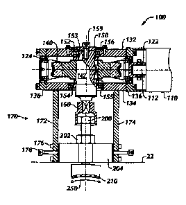
19 FIG. 2 illustrates a perspective view of a brake actuator 100
according to one embodiment, and FIG. 3 illustrates a cross-sectional view of
the
21 brake actuator 100 relative to a brake screw 200 and shoe 210 of a drive
head
22 22 for a progressive cavity pump (not shown). In use, brake actuator 100
23 controls speed of drive shaft rotation 250 by exerting force on a rotatably
24 actuated break mechanism (e.g., brake screw) 200 of a progressive cavity
pump
drive. Brake actuator 100 applies either more or less force depending on the
3

CA 02760472 2011-11-30
1 need at the time. In this way, brake actuator 100 can provide an amount of
2 braking action to keep drive shaft rotation 250 stable and within
operational
3 parameters, thereby mitigating damage to wellhead components. In addition,
4 the speed control provided by brake actuator 100 also allows brake shoe 210
to
maintain constant pressure on drive shaft rotation 250 during a braking
6 procedure and to compensate for normal wear due to friction with the drum.
7 Preferably, brake actuator 100 mounts to the progressive cavity
8 pump's drive (e.g., 20 in FIG. 1) in a way that does not interference with
other
9 wellhead components and that facilitates handling of the equipment. In FIG.
3,
for example, brake actuator 100 mounts to the drive's brake cover 204 through
11 which brake screw 200 locked by a locknut 202 puts pressure on brake shoe
12 210. Because torque transferred to screw 200 will also be transferred in
the
13 opposite direction to brake actuator 100, a mounting assembly 170 firmly
14 connects brake actuator 100 to the drive's brake cover 204. For example,
mounting assembly 170 has sidewalls 172/174 that are supported by ribs 176
16 and that mount onto the steel block of the cover 204 using anchor bolts
178.
17 Preferably, anchor bolts 178 attach the brake actuator 100 in an axial
direction to
18 brake cover 204, while sidewalls 172, 174 and ribs 176 firmly fit around
the
19 shape of brake cover 204 to prevent rotation of the brake actuator 100
during
use. Different configurations for mounting assembly 170 can be used to mount
21 the brake actuator 100 on any of the various types of drive head blocks
available
22 in the art.
23 To control rotation by the application of braking force by the brake
24 screw 200, the brake actuator 100 includes a motor 110, a reducer 120, and
an
adapter socket 160. Motor 110 can be of any type such as an electrical or a
4

CA 02760472 2011-11-30
1 hydraulic motor. Reducer 120 used to activate the brake screw 200 can use a
2 reducer system such as gears, pulleys, endless screw/crown, or the like.
3 Reducer 120 in FIGS. 2 and 3, for example, includes a screw and crown
4 mechanism having an endless screw 122 and a crown 140 positioned in a
housing 130. Screw 122 couples to a motor shaft 112 and interfaces with crown
6 140, which rotates on an exit shaft 142. In turn, exit shaft 142 couples to
the
7 head of brake screw 200 using the adapter socket 160.
8 Position of adapter socket 160 is defined as a function of its size
9 and the position of the brake screw 200's head at maximum braking capacity.
Adapter socket 160 preferably provides a space to allow brake screw 200 to
11 move in an axial direction when the brake is released. On the other hand,
12 greater movement is expected in the tightening direction so actuator 100
can
13 compensate for wear of shoe 210.
14 For reducer 120, screw 122 and crown 140 assemble between
base plates 132 and 134 of housing 130. In turn, motor 110 mounts to a side
16 plate 136, and motor shaft 112 connects directly to the reducer's screw
122.
17 Conic roll bearings 124 support this screw 122 on both side plates 136, 138
to
18 account for axial load. As for crown 140, upper and lower roller bearings
152
19 and 154 of different sizes support exit shaft 142 within base plates 132
and 134.
As best seen in FIG. 3, lower roller bearing 154 is preferably larger than
upper
21 bearing 152 to facilitate assembly. Upper and lower spacers 153 and 155 are
22 also used to keep crown 140 centered between the two bearings 152 and 154.
23 Within housing assembly 130, crown 140 attaches to exit shaft 142
24 using a cotter pin or the like. The opening for exit shaft 142 on lower
base plate
134 is sized to support bearing 154, while an upper fitting is used in the
opening
5

CA 02760472 2011-11-30
1 on upper base plate 132. This upper fitting includes a first washer 156 to
retain
2 upper bearing 152 and attached with screws to base plate 132 and includes a
3 second washer 158 attached to the end of exit shaft 142 by a central screw
159,
4 causing it to fit against upper bearing 152. Most components of brake
actuator
100 can be composed of carbon steel without the need for special treatment.
6 Exit shaft 142 is preferably composed of SAE 1045 carbon steel or other
7 thermally treated material.
8 Actuator 100 can be operated using either manual or automatic
9 operation. FIG. 4A schematically shows one form of feedback system for
automatic operation. A rotational or speed sensor 222 detects the rotation or
11 speed of the pump's drive shaft (e.g., 30 in FIG. 1). The sensor 222 can
also
12 detect the direction of rotation. Brake actuator 100 uses this sensed
information
13 (e.g., speed and/or direction) to increase or decrease the braking action
applied
14 by the existing braking system 220 of the pump's drive (e.g., brake screw
200,
shoe 210, etc.).
16 In manual operation, an operator can activate brake actuator 100
17 using a manual control 300, such as schematically shown in FIG. 4B. The
18 operator uses manual control 300 (e.g., switch, valve, dial, etc.),
according to
19 operational requirements, to increase or decrease the speed of drive shaft
30. In
this arrangement, a speed monitoring system has a sensor 310 and display 312
21 allowing the operator to read the shaft 30's speed/direction in real time.
With this
22 information, the operator, even remotely from a distance, can activate the
brake
23 actuator 100 to move brake screw 200 and shoe 210 relative to the rotation
250
24 of drive shaft 30 and either increase or decrease braking action
accordingly.
6

CA 02760472 2011-11-30
1 For automatic operation, a controller 320 shown in FIG. 4C can
2 have one or more sensors, such as a speed sensor 322 for monitoring drive
3 shaft 30, a torque sensor 324 on exit shaft 142 for monitoring torque
applied to
4 brake screw 200, a displacement sensor 326 for monitoring displacement of
brake screw 200, and a current sensor 328 for monitoring current consumption
6 of the motor 110 from a power source 329. Using measured information
7 generated by the sensors 322, 324, 326, the controller 320 can automatically
8 operate the brake actuator 100 accordingly.
9 For example, the controller 320 can use shaft speed sensor 322,
which could be any suitable type of sensor, to monitor shaft speed and control
11 the brake actuator 100. Based on the sensor signal, for example, controller
320
12 controls operation of motor 110 of the brake actuator 100 and causes the
motor
13 110 to turn one way or the other in accordance with the signal to actuate
brake
14 screw 200. Controller 320 preferably operates using predefined actuation
parameters (e.g., speed threshold) for increasing or decreasing torque applied
to
16 brake screw 200 with the actuator's motor 110. If the parameters are
exceeded,
17 then controller 320 activates motor 110 accordingly.
18 As an example of the actuation parameters, rotation 250 of drive
19 shaft 30 may be predefined for a threshold range of between 500-rpm and
1000-
rpm. Speed sensor 322 monitors speed of drive shaft 30 during operation, and
21 controller 320 monitors the measured speed. If the measured speed exceeds
22 the 1000-rpm threshold, controller 320 operates motor 110 to turn brake
screw
23 200 to increase the braking action produced. If, on the other hand, the
speed
24 falls below 500-rpm threshold, controller 320 operates motor 110 to turn in
the
proper direction to release brake screw 200 from drive shaft 30. The amount
7

CA 02760472 2011-11-30
1 with which screw 200 is applied or released can be proportional to the
amount
2 that the measured speed has fallen above or below the thresholds of the
range.
3 When controlling backspin of shaft 30, controller 320 releases
4 screw 200 so that drive shaft 30 is allowed to turn and release its
accumulated
energy. Preferably, at the time rotation begins and independent of the shaft's
6 particular speed, controller 320 stops releasing brake screw 200 momentarily
to
7 allow the shaft's speed to stabilize and balance. In this way, the speed is
8 preferably reduced progressively to the point where brake screw 200 is
9 completely loosened (but not disconnected from the drive head) and drive
shaft
30 has stopped rotating because all accumulated energy has been dissipated.
11 This progressive release is controlled automatically by controller 320 and
speed
12 sensor 322.
13 Using torque sensor 324, controller 320 can monitor the torque
14 being applied by the brake actuator 100 to the brake screw 200 so that a
maximum torque value is not exceeded. The maximum torque value depends in
16 part on the size and type of brake screw 200 used. The torque sensor 324
can
17 monitor the torque being applied to brake screw 200 by shaft 142 so that
the
18 torque does not exceed any mechanical limitations of the screw 200. This
19 torque sensor 324 can include any conventional sensor for measuring torque.
For example, torque sensor 324 can be a transducer connected to exit shaft
142.
21 As an alternative, controller 320 can monitor electric current consumed by
motor
22 110 from the power source 329 using a conventional current sensor 328 and
can
23 use this information to determine the torque being applied by the motor.
24 In addition to monitoring speed, controller 320 can monitor whether
rotation of drive shaft 30 has stopped. By default, for example, controller
320
8

CA 02760472 2011-11-30
1 may turn brake screw 200 even while drift shaft 30 is fully stopped. Using
2 displacement sensor 326, however, controller 320 can monitor the brake
screw's
3 movement or displacement. If drive shaft 30 stops rotating, the controller
320
4 can interpret this to mean that there is no remaining shaft energy and
controller
320 stops turning brake screw 200 after querying the displacement sensor 326
6 and determining that the brake screw 200 has been fully displaced. As an
7 alternative, controller 320 can determine if motor 100 is just loosening
brake
8 screw 200 without acting on the brake based on whether the consumed current
9 of the motor 110 as monitored by sensor 328 indicates minimal torque being
applied in this situation.
11 The foregoing description of preferred and other embodiments is
12 not intended to limit or restrict the scope or applicability of the
inventive concepts
13 conceived of by the Applicants. In exchange for disclosing the inventive
14 concepts contained herein, the Applicants desire all patent rights afforded
by the
appended claims. Therefore, it is intended that the appended claims include
all
16 modifications and alterations to the full extent that they come within the
scope of
17 the following claims or the equivalents thereof.
18
9

Dessin représentatif
Une figure unique qui représente un dessin illustrant l'invention.
États administratifs

2024-08-01 : Dans le cadre de la transition vers les Brevets de nouvelle génération (BNG), la base de données sur les brevets canadiens (BDBC) contient désormais un Historique d'événement plus détaillé, qui reproduit le Journal des événements de notre nouvelle solution interne.

Veuillez noter que les événements débutant par « Inactive : » se réfèrent à des événements qui ne sont plus utilisés dans notre nouvelle solution interne.

Pour une meilleure compréhension de l'état de la demande ou brevet qui figure sur cette page, la rubrique Mise en garde , et les descriptions de Brevet , Historique d'événement , Taxes périodiques et Historique des paiements devraient être consultées.

Historique d'événement

Description Date
Le délai pour l'annulation est expiré 2017-12-04
Lettre envoyée 2016-12-05
Inactive : Regroupement d'agents 2016-02-04
Accordé par délivrance 2014-02-11
Inactive : Page couverture publiée 2014-02-10
Préoctroi 2013-11-26
Modification après acceptation reçue 2013-11-26
Inactive : Taxe finale reçue 2013-11-26
Lettre envoyée 2013-06-05
Un avis d'acceptation est envoyé 2013-06-05
Inactive : Approuvée aux fins d'acceptation (AFA) 2013-05-09
Inactive : Page couverture publiée 2012-01-19
Inactive : CIB en 1re position 2012-01-06
Inactive : CIB attribuée 2012-01-06
Inactive : CIB attribuée 2012-01-05
Exigences applicables à une demande divisionnaire - jugée conforme 2011-12-20
Demande reçue - nationale ordinaire 2011-12-19
Lettre envoyée 2011-12-19
Demande reçue - divisionnaire 2011-11-30
Exigences pour une requête d'examen - jugée conforme 2011-11-30
Toutes les exigences pour l'examen - jugée conforme 2011-11-30
Demande publiée (accessible au public) 2008-06-06

Historique d'abandonnement

Il n'y a pas d'historique d'abandonnement

Taxes périodiques

Le dernier paiement a été reçu le 2013-11-25

Avis : Si le paiement en totalité n'a pas été reçu au plus tard à la date indiquée, une taxe supplémentaire peut être imposée, soit une des taxes suivantes :

  • taxe de rétablissement ;
  • taxe pour paiement en souffrance ; ou
  • taxe additionnelle pour le renversement d'une péremption réputée.

Les taxes sur les brevets sont ajustées au 1er janvier de chaque année. Les montants ci-dessus sont les montants actuels s'ils sont reçus au plus tard le 31 décembre de l'année en cours.
Veuillez vous référer à la page web des taxes sur les brevets de l'OPIC pour voir tous les montants actuels des taxes.

Historique des taxes

Type de taxes Anniversaire Échéance Date payée
TM (demande, 2e anniv.) - générale 02 2009-12-04 2011-11-30
TM (demande, 4e anniv.) - générale 04 2011-12-05 2011-11-30
Enregistrement d'un document 2011-11-30
TM (demande, 3e anniv.) - générale 03 2010-12-06 2011-11-30
Taxe pour le dépôt - générale 2011-11-30
Requête d'examen - générale 2011-11-30
TM (demande, 5e anniv.) - générale 05 2012-12-04 2012-11-22
TM (demande, 6e anniv.) - générale 06 2013-12-04 2013-11-25
Taxe finale - générale 2013-11-26
TM (brevet, 7e anniv.) - générale 2014-12-04 2014-11-13
TM (brevet, 8e anniv.) - générale 2015-12-04 2015-11-11
Titulaires au dossier

Les titulaires actuels et antérieures au dossier sont affichés en ordre alphabétique.

Titulaires actuels au dossier
WEATHERFORD INDUSTRIA E COMERCIO LTDA
Titulaires antérieures au dossier
EDUARDO PERDOMINI LARA
JORGES ROBLES VILLA
Les propriétaires antérieurs qui ne figurent pas dans la liste des « Propriétaires au dossier » apparaîtront dans d'autres documents au dossier.
Documents

Pour visionner les fichiers sélectionnés, entrer le code reCAPTCHA :


Pour visualiser une image, cliquer sur un lien dans la colonne description du document. Pour télécharger l'image (les images), cliquer l'une ou plusieurs cases à cocher dans la première colonne et ensuite cliquer sur le bouton "Télécharger sélection en format PDF (archive Zip)" ou le bouton "Télécharger sélection (en un fichier PDF fusionné)".

Liste des documents de brevet publiés et non publiés sur la BDBC .

Si vous avez des difficultés à accéder au contenu, veuillez communiquer avec le Centre de services à la clientèle au 1-866-997-1936, ou envoyer un courriel au Centre de service à la clientèle de l'OPIC.


Description du
Document 
Date
(aaaa-mm-jj) 
Nombre de pages   Taille de l'image (Ko) 
Description 2011-11-29 9 338
Revendications 2011-11-29 7 183
Abrégé 2011-11-29 1 19
Dessins 2011-11-29 3 64
Dessin représentatif 2012-01-08 1 12
Accusé de réception de la requête d'examen 2011-12-18 1 177
Courtoisie - Certificat d'enregistrement (document(s) connexe(s)) 2011-12-18 1 103
Avis du commissaire - Demande jugée acceptable 2013-06-04 1 164
Avis concernant la taxe de maintien 2017-01-15 1 178
Correspondance 2011-12-18 1 38
Correspondance 2013-11-25 2 54