Note : Les descriptions sont présentées dans la langue officielle dans laquelle elles ont été soumises.
CA 02761488 2011-11-30
1
Coupling for Ventilation Assembly
FIELD OF THE INVENTION
The present invention relates to ventilation ducts, and more particularly to a
coupling for use with ventilation elements of a ventilation ductwork assembly.
BACKGROUND OF THE INVENTION
This invention relates to a coupling for use with interconnecting ducts of a
ventilation ductwork assembly in underground passages such as mines and
tunnels.
There is presently a need for a coupling that is simple, efficient and
compatible
with interconnecting two ventilation ductwork elements made from foldable
sheets.
SUMMARY OF THE INVENTION
An object of the present invention is to provide a coupling for a ventilation
ductwork assembly that satisfies the above mentioned need.
Accordingly, the present invention provides a coupling for a ventilation duct
assembly for use with interconnecting ventilation duct elements comprising:
- a first ventilation duct element comprised of a flexible panel wherein the
flexible panel comprises:
-first and second opposite duct-forming sides;
-first and second opposite interconnecting sides for interconnection
to a subsequent panel formed into a ductwork element; and
CA 02761488 2011-11-30
2
-a connector for connecting the duct-forming sides together upon
shaping of the ductwork element and wherein the panel is shaped
into a first ductwork element with a male end smaller in diameter than
a female end;
- a second ventilation duct element comprised of a flexible panel wherein
the flexible panel comprises:
-first and second opposite duct-forming sides;
-first and second opposite interconnecting sides for interconnection
to a subsequent panel formed into a ductwork element; and
- a connector for connecting the duct-forming sides together upon
shaping of the ductwork element and wherein the panel is shaped
into a second ductwork element with a male end smaller in diameter
than the female end;
-at least one C-shaped collet shaped to fit over the connected male and
female ends of the formed ductwork elements for interconnection of
adjacent shaped ductwork elements; and
-at least one fastener for fastening the collet around the shaped ductwork
elements, and linking extremities of the C-shaped collet together.
In addition to the above, the present invention also provides a C-shaped
collet
shaped to fit over connected male and female ends of formed ductwork elements
for interconnection of adjacent shaped ductwork elements, the C-shaped collet
comprising:
-a collet strip;
CA 02761488 2011-11-30
3
-first and second opposite brackets at opposite extremities of the collet
strip,
-at least one fastener for fastening the first and second opposite brackets
together and maintaining an offset separation therebetween.
According to the present invention, there is also provided a method for
assembling
interconnecting ventilation ducts comprising the steps of:
a) inserting a female end of a formed ductwork element over a male end of
an adjacent formed ductwork element;
b) inserting a C-shaped collet over the connected male and female ends of
the formed ductwork elements, the C-shaped collet comprising:
-a collet strip; and
-first and second opposite brackets at opposite extremities of the
collet strip,
and
c) fastening the first and second opposite brackets together and
maintaining an offset separation therebetween, with at least one
fastener.
The coupling does not require that the brackets meet each other and that the
collet
encircles completely the ductwork element, which can represent material
savings,
in terms of the reduced lengths of collets to be manufactured, and add
flexibility to
the installation of the collet.
BRIEF DESCRIPTION OF THE DRAWINGS
These and other objects and advantages of the invention will become apparent
upon reading the detailed description and upon referring to the drawings in
which :
CA 02761488 2011-11-30
4
Figure 1A is a side view of a coupling for a ventilation ductwork assembly,
according to a preferred embodiment of the present invention.
Figure 1 B is a perspective view of the coupling shown in Figure 1 A.
Figure 1 C is a top view of the coupling shown in Figure 1A.
Figure 1D is a detailed side view of interconnecting sides of the ventilation
ductwork elements, before installation of the collet, according to a preferred
embodiment of the present invention.
Figure 1 E is a detailed side view of interconnecting sides of the ventilation
ductwork elements, after installation of the collet and fasteners, according
to a
preferred embodiment of the present invention.
Figure 2 is a detailed perspective view of the ventilation ductwork element
and
collet of Figure 1 E, according to a preferred embodiment of the present
invention
where the fasteners comprise a plurality of brackets.
Figure 3 is a detailed perspective view of the collet of Figure 2.
Figure 4 is a perspective view of a pallet supporting a plurality of stacked
flat
flexible panels for a ventilation duct assembly kit according to a preferred
embodiment of the present invention;
Figures 5A and 5B are perspective and detailed views respectively of a shaped
ductwork element and the associated interface between the assembled male and
female interlocking interfaces according to a preferred embodiment of the
present
invention;
CA 02761488 2011-11-30
Figures 6A to 6C are perspective views illustrating a sealing step of the
assembled
male and female interlocking interfaces according to a preferred embodiment of
the present invention;
Figure 7 is a perspective view of a slideable locking element according to a
5 preferred embodiment of the present invention;
Figure 8 is a perspective views illustrating a sealing operation of an
extremity of
the slideable locking element shown in Figure 4;
Figures 9A and 9B are a perspective views illustrating a sealing operation of
the
collets to be used in the kit according to a preferred embodiment of the
present
invention;
Figures 10A and 10B are a perspective views illustrating a fastening operation
of
the collets to the ductwork elements according to a preferred embodiment of
the
present invention;
Figures 11A and 11 B are perspective views showing assembled ductwork
elements installed for use in a tunnel according to a preferred embodiment of
the
present invention.
DETAILED DESCRIPTION OF PREFERRED EMBODIMENTS
As shown in figure 1A, the present invention provides a coupling (1) for a
ventilation duct assembly (10) for use with interconnecting ventilation duct
elements (5). This coupling comprises a first ventilation ductwork element
(5A)
comprised of a flexible panel wherein the flexible panel has first and second
opposite duct-forming sides, first and second opposite interconnecting sides
for
interconnection to a subsequent panel formed into a ductwork element (5A).
CA 02761488 2011-11-30
6
The flexible panel can be folded to form the ductwork element (5) through use
of a
male interlocking interface and a corresponding female interlocking interface
of a
fastening system that is respectively fixed on the first and second opposite
duct-
forming sides. This fastening system is used for interlocking the duct-forming
sides
together when shaping of the ductwork element.
The panel is shaped into a first truncated conical ductwork element with a
male
end that is smaller in diameter than an opposite female end. As it can be seen
in
Figures 1A 1 D and 1 E, an abutment (15) is found on the panel and on the
formed
ductwork element for restricting movement of the female end over the male end
of
an adjacent ductwork element, when inserted to form an interconnected ductwork
assembly.
As shown in Figures 1A to 1C, the present invention also involves a second
ventilation duct element (5B) comprised of a flexible panel wherein the
flexible
panel has first and second opposite duct-forming sides, such that, when
folded,
they form a second ductwork element. The panel also has first and second
opposite interconnecting sides so that the folded panel can interconnect to a
subsequent panel formed into a ductwork element.
A male interlocking interface and a corresponding female interlocking
interface of
a fastening system respectively fixed on the first and second opposite duct-
forming
sides of this panel are used for interlocking of the duct-forming sides
together
upon shaping of the ductwork element when the panel is shaped into a second
truncated conical ductwork element with a male end smaller in diameter than
the
female end. However, the ductwork element may be formed through other means,
including the use of adhesives or welding, without using interlocking
interfaces.
This panel also has an abutment (15) for restricting movement of the female
end
over the male end of an adjacent duct element.
CA 02761488 2011-11-30
7
As shown in Figure 1 B, once a first ductwork element is interconnected with a
second ductwork element, at least one collet (20) shaped to fit over the
interconnecting male and female ends of the formed ductwork elements is placed
to interconnect adjacent shaped ductwork elements (5A) and (5B), or (5B) and
(5C). It is to be appreciated that a person versed in the art would understand
that
this collet (20) is adaptable to the various sizes of the formed ductwork
elements
and to the various conditions in which this collet is to be used.
As such and as shown in Figures 1B and 1C, this collet (20) is sized to extend
between adjacent slideable locking elements from corresponding adjacent shaped
ductwork elements.
As shown in Figure 1 E, a plurality of fasteners may be used for directly
fastening
the collet (20) to the shaped ductwork elements (5A), (5B). A person versed in
the
art would appreciate that these fasteners are not limited to one type and are
adaptable to the specifications of the collet in question.
As shown in Figures 2 and 3, and according to a preferred embodiment of the
present invention, the collet is a C-shaped collet having a collet strip 30
and a
plurality of brackets 32 wherein at least one bracket is installed on each end
of the
collet strip. The brackets are fastened to the collet strip with any
appropriate
fastener or adhesive element. When both ends of the collet are placed
together,
the brackets of each end are in close proximity to one another and can be
fastened together by bracket fasteners 34, such as a screw or a bolt. As shown
in
Figures 2 and 3, the collet may be made with a material similar to that used
for the
ductwork elements. The bracket fastener is chosen to accommodate different
offset separation spacings between the end brackets of the collets such that
fastening of one bracket end to another does not require that the brackets
meet
CA 02761488 2011-11-30
8
each other and that the collet encircles completely the ductwork element,
which
can represent material savings, and add flexibility to the installation of the
collet.
In addition to the above, the present invention also provides a method for
assembling interconnecting ventilation ducts according to above. This method
involves the steps of:
a) inserting a female end of a formed ductwork element over a male end of
an adjacent formed ductwork element until it reaches an abutment;
b) inserting the collet over the overlapping male and female ends of the
interconnected adjacent ductwork elements between the respective
slideable locking elements of the interconnected adjacent ductwork
elements; and
c) fastening the collet to the adjacent formed ductwork elements with the
fasteners.
According to the present invention, there is also provided a method for
assembling
interconnecting ventilation ducts comprising the steps of:
a) inserting a female end of a formed ductwork element over a male end of
an adjacent formed ductwork element;
b) inserting a C-shaped collet shaped to fit over the connected male and
female ends of the formed ductwork elements, the C-shaped collet
comprising:
-a collet strip; and
-first and second opposite brackets at opposite extremities of the
collet strip,
and
c) fastening the first and second opposite brackets together and
maintaining an offset separation therebetween, with at least one
fastener.
CA 02761488 2011-11-30
9
The following sections give an example of how the ductwork elements can be
formed in general, according to a preferred embodiment of the present
invention.
As shown in Figures 4 to 11 B, the present invention provides a ventilation
duct
assembly kit for use for forming interconnecting ventilation ducts. The kit
comprises, as shown in Figure 4, a pallet 110 supporting a plurality of
stacked flat
flexible panels 112 that are shapeable into ductwork elements 114. As better
shown in Figure 5A, each of said flexible panels 112 comprises first and
second
opposite duct-forming sides 116,118, as well as first and second opposite
interconnecting sides 120,122, for interconnection to a subsequent panel
formed
into a ductwork element. As better shown in Figure 5B, the panel 112 also
comprises a male interlocking interface 124 and a corresponding female
interlocking interface 126 of a fastening system 128 respectively fixed on the
first
and second opposite 116,118 duct-forming sides for interlocking of the duct-
forming sides 116,118 together upon shaping of the ductwork element. As better
shown in Figures 6A to 6C, the kit also includes sealant 130 for sealing of
the male
124 and female 126 interlocking interfaces after shaping of the ductwork
element.
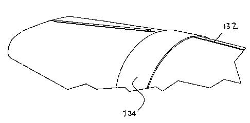
As better shown in Figure 7, the kit also includes a plurality of slideable
locking
elements 132 shaped to slide and fit over assembled male and female
interlocking
interfaces124,126 after shaping of the ductwork element 114.
Preferably, the kit also includes a plurality of collets 134 shaped to fit
over the
interconnecting sides 120,122 of the formed ductwork elements 114 for
interconnection of adjacent shaped ductwork elements 114. The collets 134 are
sized to extend between the adjacent slideable locking elements 132 from
corresponding adjacent shaped ductwork elements 114. The kit also includes a
plurality of fasteners 134 for fastening the collets 132 to the shaped
ductwork
elements 114.
CA 02761488 2011-11-30
Preferably, as shown in Figure 5B, the male interlocking interface 124 and a
corresponding female interlocking interface 126, when assembled, form a
generally trapezoidal structure with an even top surface 139. Thus the
slideable
5 locking elements 132 are shaped to fit and slide over this trapezoidal
profile and
top surface 139. Moreover, the male interlocking interface 124 preferably
comprises a projection 140, shaped to fit in a corresponding groove 142 in the
female interlocking interface 126.
10 The present invention also provides a method for assembling interconnecting
ventilation ducts, the method comprising the steps of:
a) providing a ventilation duct assembly kit, as described above;
b) taking a flat flexible panel 112 and, as better shown in Figures 5A and
5B, placing the male interlocking interface 124 of said panel into the
corresponding female interlocking interface 126 to form a ductwork element
114;
c) as better shown in Figures 6A to 6C, sealing an interface 136 between
the assembled male interlocking interface 124 and the corresponding
female interlocking interface 126 with the sealant 130;
d) as better shown in Figure 7, sliding a slideable locking element 132 over
the assembled male and female interlocking interfaces 124,126;
e) as better shown in Figure 8, sealing the extremities 138 of the slideable
locking elements 132 placed over the assembled male and female
interlocking interfaces 124,126 with the sealant 130;
f) as better shown in Figure 10A, inserting a collet 134 over an
interconnecting side of the formed ductwork element 114 until it contacts
the slideable locking element 132;
g) inserting the collet 134 over an interconnecting side of an adjacent
formed ductwork element 114 until it contacts the slideable locking element
CA 02761488 2011-11-30
11
132 of said adjacent formed ductwork element to interconnect the adjacent
formed ductwork elements; and
h) as better shown in Figure 10B, fastening the collet 134 to the adjacent
formed ductwork elements 114 with fasteners 136.
Preferably, as better shown in Figures 9A and 913, before steps f) and g),
sealant
130 is applied to the interconnecting sides of the formed ductwork elements
114 to
properly seal the joint.
Figures 11A and 11 B show the assembled ductwork elements installed for use in
a
tunnel.
The ventilation system made from the kit is preferably built in a factory or
on site
by specialized technicians. The ventilation system uses ducts made of products
produced by Quadrant EPP such as HDPE (for the more-rigid interlocking
interfaces) and copolymers (for the flexible panels), or other appropriate
plastic
materiaks. Such materials are chosen for their low friction coefficients,
their great
flexibility as well as their light weight depending on the application.
The ducts are developed with high performance equipment and tooling. The
modern method of installing the ventilation system respects the capacity of
the
equipment on which the system is built-on. Required support equipment includes
joining tools, numerical milling machines and manual extruders.
The following table shows results obtained with rigid ventilation ducts with
slideable locking elements:
CA 02761488 2011-11-30
12
October 20 October 29 November 3 November 10 November 24
Beginning of ramp 89485 CFM 80216 CFM 81687 CFM 84358 CFM 81694 CFM
After 178 m 90860 CFM 81420 CFM 77880 CFM 81892 CFM 86544 CFM
After 250 m 78771 CFM 70091 CFM 65751 CFM 67704 CFM 72261 CFM
After 333 m - - 62985 CFM 64753 CFM 66963 CFM
After 411 m - - - - 64170 CFM
Advancement - - - 437 m 471 m
(gallery in meters)
Static pressure 6.45 6.45 6.45 - 5.97
(in psi)
Note: Results obtained with an L-shaped gallery measuring 4.3 m X 4.2 m.
Steps in assembly of duct
The text below provides further descriptions of the method for assembly of the
interconnecting ducts according to a preferred embodiment of the present
invention.
The first step, shown in Figures 5A and 5B, consists in assembling two
separate
parts of a panel 112 together. The male mounting element of the interlocking
interface 124 is inserted in a groove 146 up to the bottom thereof (of the
female
interlocking interface 126).
Then, in step 2 shown in Figures 6A to 6C, a thin line of sealing material or
caulking 130 (of the type Zip & SealTM) is spread on the middle of the male
mounting element groove interface 139.
At step 3 shown in Figure 7, a metallic slideable locking element 132 is slid
on the
interface assembly at one of the extremities thereof and another slideable
locking
element 132 is placed at the other extremity.
CA 02761488 2011-11-30
13
At step 4 shown in Figure 8, a line of silicone or sealant 130 is then placed
at both
extremities of the slideable locking element 132.
At step 5 shown in Figure 10A, a junction collet 134 is then inserted over the
interface assembly until the collet 134 rests against slideable locking
elements
132.
In step 6 shown in Figures 9A and 9B, in order to provide a quality seal to
the
joints of the ducts, lines of silicone or sealant 130 are placed on the inner
side and
outer side of the ductwork elements.
In step 7 shown in Figure 10B, fasteners 136, such as support screws, are
installed on the two collets 134 (preferably 8 to 10 screws per collet).
The above-mentioned assembly steps are repeated as required to form a length
of
the duct to be built.
In step 8 shown in Figures 11A and 11B, the assembled ductwork elements 14
can then be installed in a gallery or tunnel.
The ventilation ducts built from the kit according to the method of the
present
invention offers the following advantages:
- ease of assembly
- occupies very little space when descending underground (up to 30 ducts
per pallet may be transported)
- very low friction coefficient (K factor)
- offers important energy savings
- very competitive price.
CA 02761488 2011-11-30
14
Tests have shown that the friction coefficient or K factor of ventilation
ducts made
from the kit in accordance with the present invention is generally in the
range of
2.25 to 2.5, as opposed to K factors of 9 for steel ducts or 7 for fibreglass
ducts.
These lower friction coefficients in the ducts result in energy savings as
fewer or
less power-consuming ventilation systems are required to displace a same
amount
of air through the ducts.
In addition to the main duct elements, several other ventilation accessories
are
available to interface with the ductwork elements built according to the
present
invention. These accessories include, among others: nozzles, guillotine
valves,
standard and demountable junction collets, T and Y couplings, 22.5, 45 or 90
degrees elbows, and reinforced pipes.
Of course, other types of accessories that can be made or sized to
be.compatible
with the ductwork elements according to the present invention may also be
provided.
Using the kit according to the present invention, approximately 120 feet of
ductwork can be installed in a day. Moreover, typically the equivalent 800 to
1000
feet of ductwork can be carried in a single trailer, which facilitates
transportation of
the materials to installation sites.
Although preferred embodiments of the present invention have been described in
detailed herein and illustrated in the accompanying drawings, it is to be
understood that the invention is not limited to these precise embodiments and
that
various changes and modifications may be effected therein without departing
from
the scope or spirit of the present invention.