Note : Les descriptions sont présentées dans la langue officielle dans laquelle elles ont été soumises.
CA 02761933 2011-12-13
A REUSABLE BEVERAGE CUP
BACKGROUND OF THE INVENTION
Field of the Invention
The present invention relates to beverage cups and more particularly to a
reusable take-away beverage cup.
Description of the Related Art
Most coffee outlets across the world provide coffee lovers with coffee in
disposable paper cups. These paper cups have inner polyurethane linings that
hold the
coffee piping hot for hours. However, polyurethane is not biodegradable and
billions of
disposable paper cups are used every year across the globe. Therefore, use of
disposable
paper cups results in creation of non-biodegradable toxic waste and
destruction of forests.
Efforts have been made over the years to replace the ubiquitous disposable
paper cups. These reusable cups are made of various materials from steel,
ceramic to
silicone. However, not all the reusable cups are easy to use. These reusable
cups usually
provide a concave surface along the sipping hole which unevenly distributes
the flow of
the beverage. Moreover, uneven distribution of the flow can create spillage
and cause
inconvenience to the user.
Known reusable cups incorporate a cover over the sipping hole that opens
with a shaky unidirectional movement. These cups fail to provide means for
releasing the
steam or hot air and have a tendency to lock the air within them. Therefore,
these cups
are more prone to accidental openings and spillage, when users such as
children and
elderly people try to open them.
1
CA 02761933 2011-12-13
What is needed is a reusable cup that overcomes the problems identified
above and provides a reusable drinking cup that is simple and safe to
repeatedly use.
Summary of the Invention
In accordance with the present invention there is provided a reusable beverage
cup comprising a container; a lid having an opening and adapted to fit on the
container;
and a rotatable member on the lid having a plug that is adapted to locate in
the opening
when the rotatable member is in a first position on the lid, wherein the plug
and opening
are similar in shape and sealingly close the opening
A preferred embodiment of a reusable take-away beverage container is disclosed
herein. The container is wrapped with an insulating sleeve and enclosed by a
lid. The lid
comprises a triangular shaped opening, a triangular shaped indent, a circular
shaped
indent, a central indented area and an air hole. The air hole provides a vent
for releasing
hot air or steam from the container or letting air in. The central indented
area has a
circular configuration that has a plurality of projections configured to
receive a rotating
member.
In the embodiment described herein the rotating member has a central circular
protrusion that engages with the central indented area of the lid. The plug
swivels or turns
between a first position and a second position over the lid at a predefined
angle. The
rotatable member has a triangular protrusion adapted to snap fit into the
triangular shaped
opening to define the first position of the rotatable member. The triangular
protrusion of
the rotatable member snap fits into the triangular shaped indent to define the
second
position of the rotating member. The plug has an under surface that has an
arcuate shaped
2
CA 02761933 2011-12-13
guiding track. The guiding track defines a slot along the periphery of the
rotating
member. The slot is adapted to carry the hot air or steam released by the air
hole.
In an embodiment the under surface of the plug includes a circular protrusion
defined besides the guiding track. The circular protrusion is adapted to be
positioned over
the air hole in the first position of the guiding member. The lid defines an
indentation
adapted to be positioned with the circular protrusion in the second position
of the
rotatable member.
In a preferred embodiment, the container has a tapered configuration adapted
to
fit into a variety of heads of coffee vending machines. The container has an
inner wall
marked with a plurality of predefined circular markings. The circular markings
indicate a
plurality of predefined beverage volumes. The sleeve provides a plurality of
user
customizable personalization marks. The personalization marks are configured
to be
highlighted using a marker or high-lighter.
The lid may include a bulged arcuate portion adapted to define the boundaries
within which the guiding member is allowed to turn or swivel over the lid. The
sipping
hole of the lid is accessible by a dual movement of the rotating member. The
dual
movement of the rotating member includes an upward and a lateral movement of
the
rotatable member. The triangular shaped opening laterally distributes and
controls the
flow of the beverage.
Brief Description of Drawings
The above mentioned and other features, aspects and advantages of the present
invention will become better understood with regard to following description,
appended
3
CA 02761933 2011-12-13
claims and accompanying drawings, wherein like reference numerals refer to
similar
parts throughout the several views where:
FIG. 1 is a top perspective view of a beverage cup in accordance with an
embodiment of the present invention;
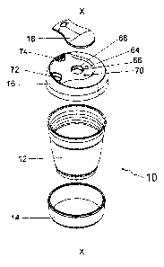
FIG. 2 is an exploded view of the cup of FIG. 1;
FIG. 3 is a front view of a container of the cup of FIG. 1;
FIG. 4 is a top perspective view of the container of the cup of FIG. 1;
FIG. 5 is a top perspective view of a sleeve member of the cup of FIG. 1;
FIG. 6 is a front view of detail on the sleeve member of the cup of FIG. 1;
FIG. 7 is atop perspective view of a lid of the cup of FIG. 1;
FIG. 8 is a bottom perspective view of the lid of the cup of FIG. 1;
FIG. 9 is a top perspective view of a plug of the cup of FIG. 1;
FIG 10 is a lower perspective view of the plug of the cup of FIG 1;
FIG. 11 is a top view of the cup of FIG. 1; and
FIG 12 is a side sectional view of the cup of FIG 1.
Description of the Preferred Embodiment of the Invention
Although specific terms are used in the following description for sake of
clarity,
these terms are intended to refer only to particular structure of the
invention selected for
illustration in the drawings, and are not intended to define or limit the
scope of the
invention.
Referring initially to FIGS. 1 and 2, a reusable take-away beverage cup 10
constructed in accordance with the present invention is disclosed. Cup 10 is
designed to
4
CA 02761933 2011-12-13
contain and carry a wide variety of hot or cold liquid beverages such as, for
example
water, tea, ice tea, milk in general, and a wide variety of hot or cold
coffees. Cup 10
includes a container 12, a sleeve 14 that sits on the container, a lid 16
attachable to the
open top of the container and a rotatable member 18 that rotates on the lid
16, all of
which are concentrically positioned to define a central longitudinal axis-X.
Container 12,
lid 16 and rotating member 18 are preferably made from reusable and flexible
thermo-
plastic polymers such as, for example, polypropylene in this one particular
embodiment
of the present invention. These polymers are rugged, tough and non-toxic and
exhibit
good resistance to fatigue. Sleeve 14 is made of an insulating and heat-
resistant material
such as, for example, silicone in this particular embodiment.
Referring to FIGS. 3 and 4, container 12 has a side wall 20 that defines an
upper
end portion 22 and a lower end portion 24. The upper end portion 22 includes a
top rim
26 that defines an opening 28 of container 12. The upper end portion 22
includes a
channel 30. Channel 30 limits and holds sleeve 14 at a predefined distance
from rim 26
where the distance is defined by an indication band 32 in side wall 20 that
facilitates firm
and exact abutment of sleeve 14 with channel 30. Channel 30 is an undercut in
band 32
that receives a corresponding ridge 48, as illustrated in Figure 12 and
described in more
detail below.
The lower end portion 24 defines a bottom rim 34. Bottom rim 34 extends
vertically downwardly from a bottom wall 36. Bottom rim 34 prevents direct
contact of
bottom wall 36 with the surface on which the container 12 is placed and
ensures the
bottom of the cup is maintained relatively clean.
5
Side wall 20 and bottom wall 36 together define a tapered configuration
adapted
to comfortably fit into a head of any coffee vending machine. Top rim 26 has
predefined
lip or space 38 that laterally extends from the sidewall along a plane that is
substantially
perpendicular to the central longitudinal axis-X. Top rim 26 has a thickness
that is
approximately equal to the thickness of sidewall 20. It is understood,
however, that the
dimensions of rim 26 may vary in other alternative embodiments for the lid 16.
Space 38
engages with lid 16 in a press fit arrangement.
Container 12 has an inner wall 40 that defines a cavity of a predefined
volume.
Inner wall 40 may have a plurality of circular markings 42 as illustrated in
FIG 4,
.. wherein each indicates a predefined volume.
Referring to FIGS. 5 and 6, sleeve 14 has an inner surface 44 and an outer
surface
46 that define a thickness 45. Inner surface 44 is adapted to be positioned
over the
container side wall 20 and directly under indication band 32. Inner surface 44
carries
ridge 48 that has substantially the same width as that of channel 30 in order
to locate
.. within channel 30. Because the material of the cup is harder than that of
the band, and
namely in the embodiment described the cup is made of a plastic such as
polypropylene
while the band is made of silicon, ridge 48 is able to locate into channel 30
under slight
compression, which assists in retaining the band on the container wall.
Outer surface 46 of sleeve 14 has a plurality of personalization marks 50,
such as,
for example, Cappuccino, Mocha, and Chai which may be used to indicate
contents by a
marking means. The personalization marks are illustrated in FIG 6.
Referring to FIGS.1, 7 and 8, lid 16 has a top surface 52, a bottom surface 54
and
a lid wall 56. The top surface 52 has a bulged or raised arcuate portion 58.
Arcuate
6
CA 2761933 2018-04-23
CA 02761933 2011-12-13
portion 58 defines boundaries on the top surface 52 within which the rotatable
member
18 is allowed to swivel or rotate over the lid 16. Arcuate portion 58 is
adapted to limit the
movement of rotatable member 18 by the limits or boundaries defined by arcuate
portion
58. Arcuate portion 58 has a first end 60 that aligns with a first side of the
rotatable
.. member 18 in a first position. Arcuate portion 58 has a second end 62 that
aligns with a
second side of rotatable member 18 in a second position.
Lid 16 includes an indentation 64 and an air hole 66. Indentation 64 has a
configuration adapted to be engaged with a circular protrusion defined on
rotatable
member 18. Air hole 66 provides a vent to release pressure that builds up when
hot
beverage is poured and sealed in container 12. Lid 16 is centrally positioned
with a
circular indent 68. Indent 68 includes a plurality of projections 70 adapted
to facilitate a
snap-fit engagement with rotatable member 18. Indent 68 extends axially
downwardly to
define a sidewall 68A and a bottom wall 68B that adjoin at a junction rim 68C.
Lid 16 defines a triangular shaped opening 72 and a triangular shaped indent
74.
Triangular shaped opening 72 has a relatively flat surface that controls and
laterally
distributes the flow of the beverage. The triangular shaped indent 74 extends
axially
downwardly to define a sidewall 74A and a bottom wall 74B that join at a
junction 74C.
While the embodiment illustrated and described has an opening, and indent,
that
is triangularly shaped, it is understood that other shapes could be used such
as oval,
.. round, square, trapezoid or the like. In a preferred embodiment, and in
order to better
distribute the flow of beverage through the opening in smaller cups, the
opening has a
shape that is wider towards the outer perimeter of the lid than towards the
centre. In other
words, the shape narrows from a radially outer position on the lid to a
radially inner
7
position. A triangle, trapezoid or a free-formed shape having a wider base
than top,
would satisfy such a requirement. In larger cups it is forseeably sufficient
to have an
opening that is round, oval, rectangular or the like.
Referring to FIGS.1, 9 and 10, rotating member 18 has a first side 73, a
second
side 75, a top surface 76 and a bottom surface 78. The top surface 76 includes
a triangular
shaped indent 80. Indent 80 is adapted to position a finger, preferably a
thumb, for
comfortable lifting and swiveling of plug 86. Rotatable member 18 has a tab 82
that
assists in lifting and turning of rotating member 18. Tab 82 has an end
portion 83 that
positions over a lid wall 56.
Bottom surface 78 has a platform 85 that has a square configuration. Platform
85
defines a protrusion, or plug, 86 that has a mating end 87. The protrusion 86
is similarly
shaped to opening 72 as it is adapted to locate in opening 72. In the drawings
the plug is
illustrated triangular in shape and together with opening 72, has cooperating
engagement
parts. Specifically, plug 86 has a triangular neck 88 that facilitates a snap
fit arrangement
with triangular shaped opening 72 and triangular shaped indent 74.
Neck 88 forms ridge around plug 86 that cooperates in a snap fit engagement
with one or more raised projections, or detents 99, on an inner wall of
opening 72 so as to
retain the plug in the opening and to also provide a seal between the plug and
opening
that prevents escape of fluid through the opening. For better sealing, detent
99 may
extend as a single projection around the internal periphery of the opening 72,
or it would
suffice to provide one or more short projections on the internal periphery
with gaps
therebetween. FIG 12 illustrates the interrelationship between the plug 86 and
opening
72.
8
CA 2761933 2018-04-23
CA 02761933 2011-12-13
The bottom surface 78 has a central circular protrusion 90. Circular
protrusion 90
has a raised circular edge 92 that provides a snap fit arrangement with the
projections 70
defined on central indent 68.
Bottom surface 78 has a guiding track 94 that has an arcuate shaped
configuration
defined by a first curved portion 94A, a second curved portion 94B, a third
curved
portion 94C and a fourth curved portion 94D. The guiding track 94 is adapted
to assist in
rotational movement of rotatatable member 18 over the lid 16. Guiding track 94
defines a
slot 95 along the periphery of the rotating member 18 adapted to carry and
release hot air
or steam released through air hole 66. Bottom surface 78 has a circular
protrusion 97
positioned besides guiding track 94. Protrusion 97 is adapted to position over
air hole 66
in the first position of the rotating member 18 to close the air hole 66 when
the rotatable
member closes the lid opening by locating plug 86 in opening 72. Protrusion 97
is
adapted to position over indentation 64 in the second position of the
rotatable member 18
to open air hole 66 when the rotatable member has moved to open the lid
opening 72.
Referring to FIGS. 1 and 11, rotatable member 18, in operation, has a first
position 96 and a second position 98. Rotatable member 18 securely engages in
a snap fit
arrangement with the projections 70 of central indent 68 in both first and
second positions
96, 98. Central protrusion 90 when engaged in a snap fit arrangement also
pivots or
rotates about central axis-X (See Fig. 1). The movement of rotatable member 18
between
the first and second positions 96, 98 is guided and secured by projections 70
and guiding
track 94.
In the first position 96, the rotatable member 18 is positioned over the
triangular
shaped opening 72 such that triangular protrusion 86 of the rotatable member
18 is
9
CA 02761933 2011-12-13
secured in a snap-fit arrangement with the triangular shaped opening 72. In
the first
position 96, triangular protrusion 86 effectively seals the container 12 to
make it spill-
proof.
In the second position 98, the rotatable member 18 is swiveled in predefined
angle
A and positioned over the indent 74. The rotational movement of the rotatable
member
18 is facilitated by pivoting central protrusion 90 within indent 68. In this
particular
embodiment, angle A is substantially 900. However, it is understood that
angle A may
vary in other alternative embodiments.
In operation
Referring to FIGS. 1-11, the use and operation of the present invention is
described. A user can use the cup 10 of the present invention in almost any
coffee shop
since configuration of the container 12 is similar to the take-away disposable
paper cups
that are available with the coffee outlet. Therefore, the cup 10 is adapted to
be used with
almost any group head of any coffee machine.
The user comes to a coffee shop and instead of the usual disposable paper cup
asks for the cup 10 of the present invention or brings one such cup with them.
The user
preferably highlights one of the personalization marks 50 to mark his choice.
The user
hands the cup to a barista. The barista removes the lid 16 by pressing
together container
12 and the lid 16. The barista fills the container 12 with the favourite
coffee of the user,
as indicated per personalization mark 50 on sleeve 14, and hands back the cup
10 to her.
The user takes the cup10 from the barista and press-fits the lid 16 over the
container 12. The user may either sip the coffee from the triangular shaped
opening 72 of
the cup 10 or seal the triangular shaped opening 72 using rotatable member 18.
The
CA 02761933 2011-12-13
sealing of the triangular shaped opening 72 is spill-proof, and the user can
carry the cup
filled with her favorite beverage wherever she goes.
The rotatable member 18 is snap-fitted within not only the triangular shaped
opening 72 but also with central indent 68. To sip the coffee from the sipping
hole 74, the
5 user first pulls the tab 82 up from the triangular shaped opening 72, and
then swivels
rotatable member 18 towards triangular indent 74 to place it inside indent 74.
Thus, upward movement of tab 82 and lateral swiveling movement of rotatable
member 18 are required to access triangular shaped opening 72 that acts as an
important
safety feature. This safety feature is particularly important, in case of
users such as
10 children and elderly people who have either not acquired or lost motor
skills to open even
a reusable and flexible coffee cup and, thereby, may accidently spill over
coffee, or other
beverages, while opening ordinary reusable beverage cups.
Another important aspect of the container 10 in accordance with the present
invention is that it is modular in construction and personalization. All the
four parts
namely, container 12, sleeve 14, lid 16 and rotatable member 18 are
customizable.
Therefore, a user can shop and choose from a variety of colors that are made
available
and personalize cup 10 according to personal tastes. Lid 16 can be used with
containers
of various sizes. Further, the modularity of design adds more reusability to
cupl 0, since
every part of the cup 10 is replaceable, reusable and interchangeable. Thus,
cup 10
constructed in accordance with the present invention further helps the user to
reduce
carbon footprint and enjoy a greener lifestyle. Additionally, disposable
takeaway
beverage cups come in standard sizes. The present beverage cup replicates this
standard
sizing.
11
CA 02761933 2011-12-13
The embodiments of the invention shown and discussed herein are merely
illustrative of modes of application of the present invention. Reference to
details in this
discussion is not intended to limit the scope of the claims to these details,
or to the figures
used to illustrate the invention.
In the claims which follow and in the preceding description of the invention,
except where the context requires otherwise due to express language or
necessary
implication, the word "comprise" or variations such as "comprises" or
"comprising" is
used in an inclusive sense, i.e. to specify the presence of the stated
features but not to
preclude the presence or addition of further features in various embodiments
of the
invention.
12