Note : Les descriptions sont présentées dans la langue officielle dans laquelle elles ont été soumises.
CA 02762511 2011-12-20
1
CONTAINER WITH LATCH
The present invention relates to an container, and more particularly, to a
container for storing and carrying tools.
Numerous storage containers are known in the art. However, there is a
constant need in the industry to improve upon existing containers by making
them
more efficient and easy to use.
One aspect provides a container having a container portion defining a space
for
storing tools and a lid portion pivotally connected to the container portion.
The lid
portion is pivotally movable between open and closed positions. The container
also
includes a latch assembly carried by the lid portion and constructed and
arranged to
latch the lid portion in the closed position. The latch assembly includes a
single latch
handle carried by the lid portion and a latch comprising spaced latch
portions, the
spaced latch portions being moveable together between a latched position and a
released position. The latch portions respectively are on opposite sides of
the latch
handle. The latch portions are engageable with latch engaging portions of the
container portion. The latch assembly also includes a spring that biases the
spaced
latch portions toward the latched position, the latch handle constructed and
arranged
to be moved to effect movement of the latch portions from the latched position
to the
released position.
These and other aspects of the present invention, as well as the methods of
operation and functions of the related elements of structure and the
combination of
parts and economies of manufacture, will become more apparent upon
consideration
of the following description and the appended claims with reference to the
accompanying drawings, all of which form a part of this specification, wherein
like
reference numerals designate corresponding parts in the various figures. In
one
embodiment, the structural components illustrated herein can be considered
drawn to
scale. It is to be expressly understood, however, that the drawings are for
the
purpose of illustration and description only and are not a limitation of the
invention. In
addition, it should be appreciated that structural features shown or described
in any
one embodiment herein can be used in other embodiments as well. As used in the
specification and in the claims, the singular form of "a", "an", and "the"
include plural
referents unless the context clearly dictates otherwise.
CA 02762511 2011-12-20
2
Fig. 1 is a perspective front view of a container, with certain components and
portions removed to better reveal others, with a latch assembly in a latched
position
and wherein some components obstructed from view are shown in dashed lines;
Fig. 2 is a perspective front view of the container with the latch assembly in
accordance with an embodiment;
Fig. 3 is a perspective rear view of the container, with certain components
and
portions removed to better reveal others, with the latch assembly in the
latched
position and wherein some components obstructed from view are shown in dashed
lines;
Fig. 4 is a rear plan view of the container in accordance with an embodiment;
Fig. 5 is a perspective front view of the container, with certain components
and
portions removed to better reveal others, with the latch assembly in a
released
position and wherein some components obstructed from view are shown in dashed
lines;
Fig. 6 is a perspective rear view of the container with the latch assembly
with
certain components and portions removed to better reveal others, with the
latch
assembly in the released position and wherein some components obstructed from
view are shown in dashed lines;
Fig. 7 is a partial cross sectional side view of the container, with certain
portions removed to better reveal others, with the latch assembly in the
latched
position in accordance with an embodiment;
Fig. 8 is a partial cross sectional side view of the container, with certain
portions removed to better reveal others, with the latch assembly in the
released
position in accordance with an embodiment;
Fig. 9 is a perspective view of the container with the latch assembly with
certain
portions removed to better reveal others; and
Fig. 10 is a partial front view (from above) of a portion of the container,
with
certain parts removed to better reveal others, in accordance with the
embodiment
shown in Fig. 9;
Fig. 11 is a partial perspective view of a portion of the container with a lid
of the
container in the open position and revealing a latch cover;
Fig. 12 is an exploded view of portions of the latch assembly and other
portions
of the container; and
Fig. 13 is a partial cross sectional view of the container, with certain
portions
removed to better reveal others, showing the latch assembly in the unlocked
position
and the latch cover.
CA 02762511 2011-12-20
3
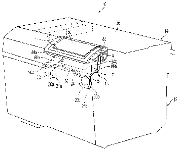
Figure 1 shows a container 10 having a container portion 12 defining a space
for storing tools. The container 10 also includes a lid portion 14 that is
pivotally
connected to the container portion 12 and that is pivotally movable between
open
and closed positions. The container 10 includes a latch assembly 16 carried by
the
lid portion 14 that is constructed and arranged to latch the lid portion 14 in
the closed
position. The latch assembly 16 includes a single latch handle 18 (see Fig. 2
)
carried by the lid portion 14. Components or portions of components that are
obstructed from view by other portions or components of the container 10 are
shown
in dashed lines. As shown in Fig. 1, the latch assembly 16 also includes a
single
latch 20 having spaced latch portions 20a, 20b that are moveable together
between a
latched position (shown in Figs. 1 and 3) and a released or unlatched position
(shown in Figs. 5 and 6). In one embodiment, the spaced latch portions 20a,
20b
may be integrally molded with one another, but in another embodiment they can
be
separately formed and then joined to form the latch 20. The latch portions
20a, 20b
respectively are on opposite sides of the latch handle 18. The latch portions
20a,
20b are engageable with latch engaging portions 22a, 22b (see Figs. 3 and 7)
of the
container portion 12. The latch assembly 16 also includes a spring 24 (see
Fig. 1)
that biases the spaced latch portions toward the latched position. The latch
handle
18 is constructed and arranged to be moved to effect movement of the latch
portions
20a, 20b from the latched position to the released position.
As shown in Fig. 2, the lid portion 14 may include a top wall or side 36, a
front
wall or side 38, a right wall or side 40, a left wall or side 42, and a back
wall or side
44. A protruding portion 39 may be provided on the front wall 38 of the lid
portion 14.
In one embodiment, the latch portions 20a, 20b are housed in the protruding
portion
39 of the lid portion 14. The lid portion 14 may be moved between an open
position
wherein access to an interior space 13 (see Fig. 11) of the container portion
12 is
permitted and a closed position wherein access to the interior space 13 of the
container portion 12 is prevented.
Referring back to Fig. 2, the container portion 12 may include a front wall or
side 48, a right wall or side 50, a left wall or side 52, a back wall or side
54, and a
bottom wall or side 56. The container portion 12 may also include a pair of
opposing
upper rims 51 formed on the left wall 52 and the right wall 50 that are
constructed
and arranged to be disposed against the lid portion 14 when the lid portion 14
is
latched to the container portion 12. A protruding portion 59 may be provided
on the
front wall 48 of the container portion 12. In one embodiment, the latch
engaging
CA 02762511 2011-12-20
4
portions 22a, 22b are housed in the protruding portion 59 of the container
portion 12.
The container 10 may include a handle 57 on the lid portion 14 to enable the
user to
lift and carry the container 10. A depression 67 formed on the top wall 36 of
the lid
portion 14 may be constructed and arranged to receive the handle 57 when the
handle 57 is not in use. The handle 57 may be pivotably attached to the top
wall 36
of the lid portion 14 via pins 63. When the handle 57 is to be used, the
handle 57
may be pivoted away from the depression 67 to a position wherein the handle 57
is
generally perpendicular to a plane defined by the top wall 36. Grooves may be
formed on the surface thereof so as to facilitate the grasping of the handle
57 during
transport of the container 10. Rubber or other friction providing materials
may
optionally be provided on the surface thereof. The handle 57 may optionally be
attached to the container 10 via hinges, snap-fit connections, or other
connecting
mechanisms and/or may be attached to the container 10 at other locations
thereof.
The lid portion 14, container portion 12, and/or any other parts of the
container 10
may be made of plastic, metal, wood, other materials, or any combination
thereof.
The lid portion 14, container portion 12, and/or other parts of the container
10 may
optionally be made from molded plastic. In one embodiment, the container 10
may
be made of a combination of metal and plastic. In addition, although the
illustrated
embodiments of the container 10 are generally rectangular, the container 10
may
have other shapes and structures.
The container 10 may also be provided with feet 49 (two are shown in this
Figure), to facilitate placement of the container 10 on a surface. Rubber,
foam, or
other materials may be provided on the surfaces of the feet 49.
In the embodiment shown in Fig. 4, the lid portion 14 is pivotally attached to
the
container portion 12 via a hinge structure 23. The hinge structure(s) 23 may
comprise any type of pivotal arrangement, such as, for example, a living hinge
or
pins and hoops. Although, in one embodiment, the hinge structure(s) 23 may
have a
permanent connection, a permanent connection is not required. It is
contemplated
that in some embodiments, a particular hinge structure 23 may be disconnected
such
that the lid portion 14 and the container portion 12 are no longer attached by
the
hinge structure 23. It should be appreciated that the lid portion 14 may also
be other
types of lids, such as, just for example, a snap fit lid or an accordion type
lid.
Referring back Fig. 2, the lid portion 14 may also include a first section 68
and
a second section 70. In the illustrated embodiment, elongated ridges 72 are
provided on the surfaces thereof. However, it is contemplated that in other
embodiments, the surfaces of the first section 68 and second section 70 may be
CA 02762511 2011-12-20
smooth or may have other shapes or structures provided thereon. The first
section
68 and the second section 70 may be pivotally attached to the lid 16 and may
be
pivoted between an open position wherein access to storage spaces (not shown)
under the first and second sections 68, 70 is permitted and a closed position
wherein
5 access to the storage spaces is prevented. In this embodiment, a first
depression 74
is provided in the front wall 38 of the lid portion 14 beneath the first
section 68, and a
second depression 76 is provided in the front wall 38 of the lid portion 14
beneath the
second section 70. Accordingly, the first and second depressions 74, 76 enable
a
user to insert fingers therein to pivot the first and sections 68, 70,
respectively,
between open and closed positions so as to permit and prevent access to the
storage spaces.
As mentioned above, the latch handle 18 is carried by the lid portion 14. In
the
illustrated embodiment, the latch handle 18 is pivotally attached to the lid
portion 14
and may be pivoted along pivot axis A (see Fig. 1). The pivot axis A may be
defined
by protrusions 83 (one is shown in Fig. 12) that are provided on the latch
handle 18
to connect the latch handle 18 to the lid 14. The protrusions 83 may be
received in
recesses 91 (two are shown in Fig. 12) provided in the lid 14 to enable
pivotal
movement of the latch handle 18. In other embodiments, the latch handle 18 may
be pivotally attached to the lid portion 14 using pivot pins or other
attachment
mechanisms. The latch handle 18 includes a handle portion 80. The handle
portion
80 may be located on the top wall 36 of the lid portion 14. In this
embodiment, a
depression 82 is formed in the lid portion 14 underneath the handle portion
80. The
depression 82 may be constructed and arranged to receive a user's fingers so
as to
facilitate the user in pivoting the latch handle 18 to operate the latch
assembly 16.
A lock 120, which may take the form of a cylinder lock, may be provided on the
lid portion 14 so as to lock the lid 14 in the closed position to secure the
contents
therein and to prevent unauthorized access to the contents therein. In one
embodiment, the cylinder lock 120 may be used to lock the lid 14 so as to
prevent
pivoting movement thereof to the open position. In such embodiment, the latch
handle 18 may still be lifted to its pivoted position. Alternatively, in one
embodiment,
the lock 120 may be used to lock the latch handle 18 in its unpivoted, default
position
so as to prevent the latch handle 18 from being pivoted to move the latch
assembly
16 to the released position.
Although the latch handle 18 is a separate structure in the illustrated
embodiment, it should be appreciated that the latch handle 18 may be
integrally
molded with the latch 20 or attached to the spaced latch portions 20a, 20b in
other
CA 02762511 2011-12-20
6
embodiments. In such embodiments, the latch handle 18 and the spaced latch
portions 20a, 20b may be pivotable about a common axis. The spaced latch
portions
20a, 20b comprise separated teeth of the single latch 20.
Referring back to Fig. 1, the latch handle 18 may also include one or more
latch
contact portions 84a, 84b (two shown) extending from the handle portion 80. As
further illustrated in this embodiment, the spaced latch portions 20a, 20b may
be
integrally formed with a main latch portion 17. That is, the main latch
portion 17 may
be an elongated portion disposed between and integrally formed with the spaced
latch portions 20a, 20b. As mentioned above, the spaced latch portions 20a,
20b are
constructed and arranged to engage with the latch engaging portions 22a, 22b.
In
one embodiment, the integral structure of the spaced latch portions 20a, 20b
enables
the lid portion 14 to be stably latched to the container portion 12. The
integral
structure of the spaced latch portions 20a, 20b may also provide efficient
latching
because of the minimal number of moveable components used to latch the lid
portion
14 to the container portion 12.
The latch 20 may also include one or more extending portions 86a, 86b (two
shown). In this embodiment, the extending portions 86a, 86b are constructed
and
arranged to contact the one or more latch contact portions 84a, 84b of the
latch
handle 18, respectively. Accordingly, the latch handle 18 is constructed and
arranged to operate with the main latch portion 17 and the spaced latch
portions 20a,
20b via the contact between the latch contact portions 84a, 84b and the
extending
portions 86a, 86b to move the spaced latch portions 20a, 20b between the
latched
and released positions. In one embodiment, the extending portions 86a, 86b may
be
integrally formed with the main latch portion 17. In other embodiments, the
extending
portions 86a, 86b may optionally integrally form a single extending portion.
The latch
20 may be pivotally connected to the lid portion 14 via a rod 88. Thus, the
main latch
portion 17 and the latch portions 20a, 20b are pivotable about an axis defined
by the
rod 88. The rod 88 may be received in openings 89 (see Fig. 12) formed in the
latch
20 between the extending portions 86a, 86b and stop portions 90a, 90b
extending
from the latch 20. As shown in Fig. 1, the rod 88 may define an axis B along
which
the latch 20 may pivot. In one embodiment, the axis B defined by the rod 88 is
parallel to the pivotal axis A of the latch handle 18.
In the illustrated embodiment, however, relative movement between the handle
18 and the latch 20 is permitted. For example, when the lid 14 is closed and
such
closing action forces the latch 20 to pivot, the handle 18 does not pivot
along with the
CA 02762511 2011-12-20
7
latch 20, as the member 84b disengages away from the member 86b (as can be
appreciated from Fig. 7).
In one embodiment, the stop portions 90a, 90b may extend generally in the
same direction as the latch portions 20a, 20b. In one embodiment, the spring
24
may be located on the rod 88 (see Fig. 1) and may take the form of a torsion
spring.
As shown in Fig. 1, the spring 24 may be wrapped around at least a portion of
the rod
88 and may bias the latch 20, including the latch portions 20a, 20b, toward
the
latched position. It should be appreciated that the single spring 24 may be
located in
other locations and/or may be other types of springs. For example, in one
embodiment, the spring 24 may be a tensile spring with one end attached to the
latch
and the other end attached to another portion of the container 10 so as to
bias the
latch 20 (and thus the latch portions 20a, 20b) in the latched position.
Fig. 7 shows the latch assembly 16 in the latched position. In the latched
position, the latch handle 18 is in the unpivoted, default position. In the
illustrated
15 embodiment, the latch contact portion 84b of the latch handle 18 is in
contact with the
extending portion 86b of the latch 20. In particular, in this embodiment, the
latch
contact portion 84b of the latch handle 18 includes a hooked portion 92
constructed
and arranged to engage with an end portion 94 of the extending portion 86b of
the
latch 20. In addition, when the latch assembly 16 is in the latched position,
the stop
20 portion 90b of the latch 20 may abut against a stop surface 96 of the lid
portion 14.
Accordingly, the contact between the stop portion 90b and the stop surface 96
may
prevent over-rotation of the latch 20 in the clockwise direction due to bias
of the
spring 24. A similar stop surface (not shown) may be provided to contact the
stop
portion 90a (obstructed from view in this Figure).
In the illustrated embodiment, the latch portion 20b includes a hooked portion
or projection 21b. The latch portion 20b includes a corner 100 and a first
contact
surface 98 adjacent to the corner 100. A slanted camming surface 102 extends
generally downwards from the first contact surface 98. The corner 100, the
first
contact surface 98, and the slanted camming surface 102 may define the
projections
21 b. A similar projection 21 a may be provided on the latch portion 20a.
In the illustrated embodiment, the latch engaging portion 22b includes a
recess
99b constructed and arranged to receive the projection 21b of the latch
portion 20b.
The recess 99b is partially defined by a tip 108 and a second contact surface
104
constructed and arranged to engage with the first contact surface 98 of the
latch
portion 20b when the latch assembly 16 is in the latched position. The latch
engaging portion 22b may include a similar recess 99a as the recess 99b. In
this
CA 02762511 2011-12-20
8
embodiment, the latch engaging portion 22b also includes a slanted third
contact
surface 110 adjacent the tip 108. The camming surface 102 of the latch 20 is
constructed and arranged to contact the slanted third surface 110 during the
latching
operation, which will be described in more detail later.
Although Fig. 7 shows the latch portion 20b and the latch engaging portion
22b,
it is contemplated that that the latch portion 20a and latch engaging portion
22a may
be constructed and arranged in a similar manner. Accordingly, the latch
portion 20a
and the latch engaging portion 22a may operate in a similar manner as the
latch
portion 20b and the latch engaging portion 22b.
Fig. 8 illustrates the latch assembly 16 in the released position in
accordance
with an embodiment. In the illustrated embodiment, the latch handle 18 is in a
pivoted position such that the latch contact portion 84b is rotated clockwise
from its
position shown in Fig. 7 when the latch handle 18 is in the unpivoted, default
position.
In addition, the extending portion 86b of the latch 20 is rotated
counterclockwise from
its position shown in Fig. 7. The end portion 94 of the extending portion 86b
is
removed from the hooked portion 92 of the latch contact portion 84b and is
slid to a
higher position on a sliding surface 112 of the latch contact portion 84b.
Furthermore, in the unlatched position, the tip 108 of the latch engaging
portion 22b
is removed from the corner 100 of the latch portion 20b. As a result, when the
latch
assembly 16 is in the unlatched position, the latch engaging portion 22b is
disengaged from the latch portion 20b and the lid portion 14 may be pivoted to
the
open position away from the container portion 12.
Fig. 9. is a perspective view of the container 10 with certain parts removed
to
better reveal others. In this embodiment, the container 10 includes a latch
cover 123
that may be optionally provided in the lid 14. The latch cover 123 may include
a
protrusion 125 constructed and arranged to engage with a portion of the lid 14
so as
to attach the latch cover 123 to the lid 14. The attachment of the latch cover
123 to
the lid 14 will be described in more detail later. The latch cover 123 may be
constructed and arranged to block access/view of at least portions of the
latch 20
when the lid 14 is pivoted to the open position (see Fig. 11). Fig. 10
illustrates a
frontal view (from above) of the container 10 with certain parts removed to
better
reveal others. In this embodiment, the container 10 includes the latch cover
123.
The example of the latch cover 123 is not intended to be limiting, and it is
contemplated that the location of the latch cover 123 and the connection
mechanism
used to connect the latch cover 123 to the lid 14 may vary in other
embodiments.
CA 02762511 2011-12-20
9
Fig. 11 shows the lid 14 in the open position in accordance with an
embodiment. The lid 14 includes opposing lower side walls 138a, 138b. The
latch
cover 123 may be positioned between the lower side walls 138a, 138b.
Accordingly,
the latch cover 123, the lower side walls 138a, 138b, a lower rear wall 142
(see Fig.
13), and a lower wall 130 (see Fig. 12) of the lid 14 may form a latch housing
140
that encloses at least portions of the latch 20 within the latch housing 140.
Thus, the
latch cover 123 and the other parts of the latch housing 140 may block access
to/view of the portions of the latch 20 and/or other parts of the latch
assembly 16.
In one embodiment, the portions of the latch 20 that are engaging/contacting
the spring 24 and the rod 88 may be hidden from view by the latch housing 140.
Accordingly, the cover latch 123 and other parts of the latch housing 140 may
prevent objects or fingers from becoming lodged in parts of the latch assembly
16
(e.g., near the points of contact between the latch contact portions 84a, 84b
of the
latch handle 18 and the extending portions 86a, 86b of the latch 20, near the
pivot
axis B of the latch 20 defined by the rod 88). As shown in Fig. 11, a recess
127 is
provided in the latch cover 123 for the latch portions 20a, 20b to extend
therethrough
so that the latch portions 20a, 20b may engage with the latch engaging
portions 22a,
22b (obstructed from view in this Figure) of the container portion 12.
Fig. 12 illustrates an exploded view of the latch assembly 16 and other
portions
of the container 10. In the illustrated embodiment, the lid 14 includes a
recessed
portion 128 constructed and arranged to receive the handle 18. The recessed
portion 128 may include the depression 82 for receiving the user's fingers
during
movement of the latch handle 18. The recessed portion 128 may be partially
defined
by the lower wall 130 of the lid 14. The latch 20 may be pivotally connected
to the lid
14 under the recessed portion 128 (see Fig. 13). As shown in Fig. 12, the
latch cover
123 includes fingers 129 extending from opposite ends of the latch cover 123
with
the recess 127 therebetween. It should be appreciated that in other
embodiments,
the location, construction, and number of the fingers 129 may vary. The latch
cover
123 may also include a raised periphery 131 that surrounds at least portions
of the
latch cover 123. The fingers 129 and the raised periphery 131 may help guide
and
connect the latch cover 123 to the lid 14 during the arrangement of the cover
latch
123 on the lid 14 of the container 10. In one embodiment, the raised periphery
131
may contact the lower side walls 138a, 138b of the lid 14 when the latch cover
123 is
attached to the lid 14. In addition, the protrusions 125 with hook-shaped ends
(three
are shown in this embodiment) may also be constructed and arranged to connect
the
latch cover 123 to the lid 14. As shown in Fig. 13, the lid 14 may include the
lower
CA 02762511 2011-12-20
rear wall 142 that extends downward from the lower wall 130. As mentioned
above,
the lower rear wall 142, the lower wall 130, and the latch cover 123 help
define the
lock housing 140. Thus, the cover latch 123 may be attached to the lower rear
wall
142 of the lid 14. For example, the lower rear wall 142 may be provided with
5 engaging members 144 constructed and arranged to engage with the hook-shaped
ends of the protrusions 125. A portion of the raised periphery 131 may also
contact
the lower rear wall 142 when the latch cover 123 is attached to the lid 14.
The
attachment of the latch cover 123 to the lid 14 may vary in other embodiments.
It is
also contemplated that the latch cover 123 may be optional. For example, in
some
10 embodiments, the container 10 is not provided with the latch cover 123.
The lid portion 14 may be latched to the container portion 12 as follows in
accordance with an embodiment. The lid portion 14 may initially be in the open
position wherein contents of the container portion 12 can be accessed. The lid
portion 14 may then be pivoted towards the container portion 12. As the lid
portion
14 is moved towards the container portion 12, the slanted camming surfaces 102
of
the latch portions 20a, 20b of the latch 20 may cam against the slanted third
surfaces
110 of the latch engaging portions 22a, 22b. During the camming movement, the
latch 20 may be rotated in the counterclockwise direction against the bias of
the
spring 24 due to camming force between the slanted camming surfaces 102 of the
latch portions 20a, 20b and the slanted third surfaces 110 of the latch
engaging
portions 22a, 22b. The slanted camming surfaces 102 of the latch portions 20a,
20b
may cam against the slanted third surfaces 110 of the latch engaging portions
22a,
22b until the tip 108 of the latch engaging portions 22a, 22b clear the
camming
surfaces 102 of the latching portions 20a, 20b so that the latch portions 20a,
20b are
in the unlatched position, whereupon the spring 24 may snap the latch portions
20a,
2b towards the latch engaging portions 22a, 22b. Accordingly, the second
contact
surfaces 104 of the latch engaging portions 22a, 22b may slide against the
first
contact surfaces 98 of the latch portions 20a, 20b until the tips 110 of the
latch
engaging portions 22a, 22b are received in the corners 100 of the latch
portions 20a,
20b. The stop portions 90a, 90b of the latch 20 may abut against the stop
surfaces
96, thus preventing over-rotation in the clockwise direction of the latch 20.
As a
result, the projections 21 a, 21b of the latch portions 20a, 20b are received
in the
recesses 99a, 99b of the latch engaging portions 22a, 22b. That is, the latch
portions
20a, 20b are in the latched position with the latch engaging portions 22a,
22b, as
shown in Fig. 7. Thus, the lid portion 14 may be "automatically" latched to
the
CA 02762511 2011-12-20
11
container portion 12 by simply moving the lid portion 14 towards the container
portion
12.
It should be appreciated that, in one embodiment, the user may be required to
push the lid portion 14 towards the container portion 12 with force to latch
the lid
portion 14 to the container portion 12. In an alternate embodiment, gravity
alone can
move the lid portion 14 to the latched position. That is, in one embodiment,
the lid
portion 14 may optionally have a weight that is sufficiently heavy in relation
to the
spring constant of the spring 24 such that the force of gravity alone is
enough to
move to the lid portion 14 to the closed position, whereupon the lid assembly
16 may
"automatically" latch the lid portion 14 to the container portion 12 as
described above.
In one embodiment, the lid portion 14 may have sufficient weight such that the
force
of gravity alone is sufficient to move the lid portion 14 to the latched
position when
the lid portion 14 is released from any position. Alternatively, in one
embodiment, the
force of gravity alone is sufficient to move the lid portion 14 to the latched
position
only when the lid portion 14 is released from higher than a predetermined
height
position. For example, in one embodiment, the lid portion 14 may be moved to
the
latched position by the force of gravity when the lid portion 14 is released
from a
position wherein the angle between a plane defined by the lid portion 14 and a
plane
defined by the pair of opposing upper rims 51 of the container portion 12 is
at least
45 degrees. The relative orientations can easily be changed, and not limiting,
as can
be appreciated by those skilled in the art.
Alternatively, the lid portion 14 may be latched to the container portion 12
as
follows. The user may lift the latch handle 18 such that the latch handle 18
is rotated
in the clockwise direction, as shown in Fig. 8, from its unpivoted, default
position
(shown in Fig. 7). Thus, the latch contact portions 84a, 84b of the latch
handle 18
are also pivoted in the clockwise direction. The contact between the latch
contact
portions 84a, 84b and the extending portions 86a, 86b may cause the latch
contact
portions 84a, 84b to push the extending portions 86a, 86b so that the latch 20
is
rotated in the counterclockwise direction around the rod 88 to the unlatched
position.
As a result, the lid portion 14 may be placed on the container portion 12
without the
third slanted surface 110 of the latch engaging portions 22a, 22b obstructing
the latch
portions 20a, 20b. After the lid portion 14 has been placed on the container
portion
12 such that the latch portions 20a, 20b are located beneath the latch
engaging
portions 22a, 22b, the user may let go of the latch handle 18, whereupon the
spring
24 may snap the latch 20 in the clockwise direction. Accordingly, the second
contact
surface 104 of the latch engaging portions 22a, 22b may slide against the
first
CA 02762511 2011-12-20
12
contact surface 98 of the latch portions 20a, 20b until the tips 110 of the
latch
engaging portions 22a, 22b are received in the corner 100 of the latch
portions 20a,
20b. The stop portions 90a, 90b of the latch 20 may abut against the stop
surfaces
96, thus preventing over-rotation in the clockwise direction of the latch 20.
The ends
94 of the extending portions 86a, 86b may be received in the hooked portion 92
of
the latch handle 18. During rotation of the latch 20 by the bias of the spring
24, the
extending portions 86a, 86b of the latch 20 may push against the contact
portions
84a, 84b of the latch handle 18, and thus rotate the latch handle 18 in the
counterclockwise direction until the latch handle 18 is in the unpivoted,
default
position, as shown in Fig. 7. Accordingly, the latch portion 20a, 20b are in
the
latched position with the latch engaging portions 22a, 22b, as shown in Fig.
7. That
is, the projections 21a, 21b of the latch portions 20a, 20b are received in
the
recesses 99a, 99b of the latch engaging portions 22a, 22b.
The lid portion 14 may be unlatched from the container portion 12 as follows
in
accordance with an embodiment. The lid portion 14 may initially be latched to
the
container portion 12, as shown in Fig. 7. The engagement between the latch
engaging portions 22a, 22b and the latch portions 20a, 20b may prevent the lid
portion 14 from being moved to the open position. That is, attempts to lift
the lid
portion 14 from the container portion 12 may cause the first contact surfaces
98 of
the latch portion 20a, 20b to abut against the second contact surfaces 104 of
the
latch engaging portions 22a, 22b. The user may then insert fingers into the
depression 82 to pivot the handle portion 80 of the latch handle 18 upwards.
As the
handle 18 is pivoted upwards, the handle 18 is rotated in the clockwise
direction.
Accordingly, the latch contact portions 84a, 84b of the latch handle 18 are
also
rotated in the clockwise direction. The latch contact portions 84a, 84b may
push
against the extending portions 86a, 86b of the latch 20, thus pivoting the
extending
portions 86a, 86b (and the rest of the latch 20) in the counterclockwise
direction
around the rod 88. The ends 94 of the extending portions 86a, 86b may slide
upwards on the sliding surfaces 112 of the latch contact portion 84b during
the
pivoting movement, as shown in Fig. 8. As the latch 20 is rotated in the
counterclockwise direction, the second contact surfaces 104 of the latch
engaging
portion 22a, 22b are slid out of engagement with the first contact surfaces 98
of the
latch portions 20a, 20b and the tips 108 of the latch engaging portions 22a,
22b are
removed from the corners 100 of the latch portions 20a, 20b. Accordingly, the
latch
portions 20a, 20b are in the release position and are no longer engaged with
the
latch engaging portions 22a, 22b. The lid 16 may then be pivoted upwards to
the
CA 02762511 2011-12-20
13
open position. Thus, the latch assembly 16 is constructed and arranged to
enable
unlatching of the spaced latch portions 20a, 20b by pivotal movement of the
latch
handle 18.
In some embodiments, the container 10 may be divided into compartments or
may include removable compartments. In one embodiment, the compartments may
be defined by container member or dividers. The container members may
optionally
be constructed and arranged to be removable and to be insertable at various
locations in the container portion 12 so that the configuration of the
compartments
may be changed. The container members may also be removed completely from the
container portion 12 so that larger compartments may be formed by the walls of
the
container 10 and/or the walls of the other container members. The container
members may also be removed to be carried separately. The container members
may optionally have various shapes and/or various sizes. The container portion
12
may optionally include inserts made of a flexible or memory-retaining
materials with
depressions formed therein to receive objects. In some embodiments, the
depressions may be the same shape as the tools. In some embodiments, the
inserts
may be made of foam material. It should also be appreciated that trays 124
having
an optional handle portion 126 (see Fig. 11) or other containers may be
provided in
the interior space 13 of the container 10.
It should be appreciated that the examples described above are not intended to
be limiting. It is contemplated that the latch assembly 16 may be used in
other types
of boxes or containers. For example, the latch assembly 16 may be incorporated
in
the containers of the rolling container assembly described in U.S. Patent
Application
Serial No. 12/858,376, which is incorporated herein in its entirety.
Although the invention has been described in detail for the purpose of
illustration based on what is currently considered to be the most practical
and
preferred embodiments, it is to be understood that such detail is solely for
that
purpose and that the invention is not limited to the disclosed embodiments,
but, on
the contrary, is intended to cover modifications and equivalent arrangements
that are
within the spirit and scope of the appended claims. For example, it is to be
understood that the present invention contemplates that, to the extent
possible, one
or more features of any embodiment may be combined with one or more features
of
any other embodiment.